Chamberlain HD920EV Manual

Chamberlain HD920EV Manual

Belt drive battery backup garage door opener
Hide thumbs Also See for HD920EV:

Advertisement

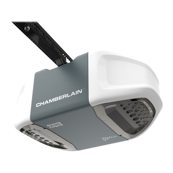
Belt Drive Battery Backup Garage Door Opener
HD920EV • 349544 • WD962KEV • WD962KPEV
Write down the following information for
future reference:
Model Number:
Serial Number:
Date of Purchase:
Models
FOR RESIDENTIAL USE ONLY
■ Please read this manual and the enclosed safety materials carefully!
■ Fasten the manual near the garage door after installation.
■ The door WILL NOT CLOSE unless the Protector System
aligned.
■ Periodic checks of the garage door opener are required to ensure safe operation.
■ The model number label is located on the left side panel of your garage door opener.
■ This garage door opener is compatible with MyQ™ and Security✚ 2.0™ accessories.
■ DO NOT enable the Timer-to-Close feature if you are installing the garage door opener
on a one-piece door. The Timer-to-Close is to be used ONLY with sectional doors.
.
®
is connected and properly
www.chamberlain.com
The Chamberlain Group, Inc.
845 Larch Avenue
Elmhurst, Illinois 60126-1196
CONTENTS
Preparation . . . . . . . . . . . . . . . .2-5
Assembly . . . . . . . . . . . . . . . . 6-10
Installation . . . . . . . . . . . . . . 11-20
Install the Door Control . . . . . . 21-23
®
. . 23-26
Power. . . . . . . . . . . . . . . . . . 27-28
Adjustments . . . . . . . . . . . . . 29-31
Battery Backup. . . . . . . . . . . . 32-33
Operation . . . . . . . . . . . . . . . . . 34
Features . . . . . . . . . . . . . . . . . . 35
Door Control . . . . . . . . . . . . . 36-38
Remote Control . . . . . . . . . . . 39-40
To Erase the Memory . . . . . . . . . 40
Maintenance . . . . . . . . . . . . . . . 42
Troubleshooting. . . . . . . . . . . 43-44
Repair Parts . . . . . . . . . . . . . 45-46
Accessories. . . . . . . . . . . . . . . . 47
Warranty. . . . . . . . . . . . . . . . . . 48

Advertisement

Table of Contents
loading
Need help?

Need help?

Do you have a question about the HD920EV and is the answer not in the manual?

Questions and answers

Summary of Contents for Chamberlain HD920EV

  • Page 1: Table Of Contents

    Installation ....11-20 Models Install the Door Control ..21-23 HD920EV • 349544 • WD962KEV • WD962KPEV Install the Protector System ®...
  • Page 2: Preparation

    Preparation Safety Symbol and Signal Check the Door Word Review 1. Disable locks and remove any ropes connected to the garage door. This garage door opener has been designed and To prevent possible SERIOUS  NJURY or 2. Lift the door halfway up. Release the tested to offer safe service provided it is installed, DEATH: door.
  • Page 3 Preparation üAdditional items you may need: Tools Needed Survey your garage area to see if you will need any of the following items: (2) 2X4 PIECES OF WOOD May be used to fasten the header bracket to the structural supports. Also used to position the garage door opener during installation and for testing the safety reversing sensors.
  • Page 4: Carton Inventory

    Preparation Carton Inventory Your garage door opener is packaged in one carton which contains the motor unit and all parts illustrated below. Accessories vary depending on the garage door opener model purchased. Depending on your model, other accessories may be included with your garage door opener. Instructions for these accessories will be attached to the accessory and are not included in this manual. If anything is missing, carefully check the packing material.
  • Page 5 Preparation Carton Inventory ASSEMBLY HARDWARE INSTALLATION HARDWARE Bolt Bolt Lag Screw 5/16"-18x1-7/8" (2) Lag Screw 5/16"-9x1-5/8" (2) Ring Fastener (3) 1/4"-20x1-3/4" (2) Clevis Pin 5/16"x1" Clevis Pin 5/16"x1-1/4" Clevis Pin 5/16"x1-1/2" Threaded Shaft with Master Link Spring Trolley Nut Self-Threading Screw Hex Bolt 5/16"-18x7/8"...
  • Page 6: Assembly

    Assembly 1 Assemble the rail and trolley To avoid installation difficulties, do not run the To garage garage door opener until instructed to do so. Outer Trolley door opener To prevent NJURY from pinching, keep hands Assemble the trolley by sliding the inner and fingers away from the joints while assembling trolley into the outer trolley.
  • Page 7 Assembly 2 Fasten the rail to the garage door opener Bolts NOTE: ONLY use the bolts removed from the garage door opener. Place the garage door opener on the packing material to prevent To avoid SERIOUS damage to garage door “U”...
  • Page 8 Assembly 3 Install the pulley HARDWARE Bolt Bolt 1/4"-20x1-3/4" Lay the belt beside the rail, as shown. Grasp the end with the hooked trolley connector and pass approximately 12" (30 Screwdriver cm) of belt through the window. Keep the ribbed side toward the rail, and allow it to Rail hang.
  • Page 9: Install The Belt

    Assembly 4 Install the belt Pull the belt around the pulley and toward HARDWARE the trolley. The ribbed side must contact the pulley. Threaded Shaft Master Link with Hook the trolley connector into the retaining slot on the trolley as shown. Spring With the trolley against the screwdriver, Trolley Nut...
  • Page 10: Tighten The Belt And Install The Sprocket Cover

    Assembly 5 Tighten the belt and install the sprocket cover By hand, thread the spring trolley nut on the Insert a flathead screwdriver tip into one threaded shaft (H8) until it is finger tight of the nut ring slots and brace it firmly against the trolley.
  • Page 11: Important Installation Instructions

    Installation IMPORTANT INSTALLATION INSTRUCTIONS To reduce the risk of SEVERE INJURY or DEATH: 9. Install wall-mounted garage door control: 1. READ AND FOLLOW ALL INSTALLATION WARNINGS AND INSTRUCTIONS. 2. Install garage door opener ONLY on properly balanced and lubricated garage door. An •...
  • Page 12 Installation Determine the header bracket Installation procedures vary according to garage door types. Follow the instructions which apply to your Unfinished OPTIONAL door. location CEILING Ceiling Close the door and mark the inside vertical centerline of the garage door. MOUNT FOR Header Wall HEADER Extend the line onto the header wall above the door.
  • Page 13: Install The Header Bracket

    Installation 2 Install the Header Bracket You can attach the header bracket either to the OPTION A WALL INSTALLATION wall above the garage door, or to the ceiling. Vertical (Header Wall) 2.1A Center the bracket on the vertical Follow the instructions which will work best for Centerline of Wall Mount centerline with the bottom edge of the...
  • Page 14: Attach The Rail To The Header Bracket

    Installation Attach the rail to the header bracket HARDWARE Align the rail with the header bracket. Insert the clevis pin Clevis Pin 5/16"x1-1/2" (H12) through the holes in the header bracket and rail. Secure with the ring fastener (H19). NOTE: Use the packing material as a protective base for the garage door Ring Fastener opener.
  • Page 15 Installation Hang the garage door opener HARDWARE H10 (2) H15 (2) H21 (2) H20 (2) Lag Screw 5/16"- 18x1-7/8" Hex Bolt 5/16"- 18x7/8" Nut 5/16"-18 Lock Washer 5/16"-18 To avoid possible SERIOUS NJURY from a falling garage door opener, fasten it SECURELY to structural supports of the garage.
  • Page 16: Installation

    Installation Install the light bulbs Pull on the top sides of the light lens and rotate the light lens down. Insert an A19 incandescent or compact To prevent possible OVERHEAT NG of the end panel or light socket: fluorescent light bulb (100 watt maximum), •...
  • Page 17: Install The Door Bracket

    Installation FIGURE 1 Install the door bracket A horizontal and vertical reinforcement is needed for lightweight garage doors (fi berglass, aluminum, steel, doors with glass panel, etc.) (not provided). A horizontal reinforcement brace should be long enough to be secured Fiberglass, aluminum or lightweight steel garage doors WILL REQUIRE reinforcement BEFORE to two or three vertical supports.
  • Page 18 Installation Install the door bracket OPTION B ONE-PIECE DOORS 8.1B Center the door bracket on the top of the door, in line with the header bracket as shown. Metal Door 8.2B Mark either the left and right, or the top (Finished Ceiling) Top of Door Header Wall and bottom holes.
  • Page 19: Connect The Door Arm To The Trolley

    Installation 9 Connect the door arm to the trolley Installation will vary according to the garage door type. Follow the instructions which apply to your door. IMPORTANT: The groove on the straight door arm MUST face away from the curved door arm (Figure 1). OPTION A ONE-PIECE DOORS 9.1A...
  • Page 20 Installation 9 Connect the door arm to the trolley OPTION B SECTIONAL DOORS IMPORTANT: The groove on the straight door arm HARDWARE FIGURE 1 MUST face away from the curved door arm (Figure 1). CORRECT INCORRECT 9.1B Close the door. Disconnect the trolley by pulling the emergency release handle.
  • Page 21: Install The Door Control

    6ABx1-1/2" (2) compatible with up to 2 MyQ™ door controls. • Be sure power is NOT connected BEFORE installing door control. NOTE: Older Chamberlain door controls and • Connect ONLY to 12 VOLT low voltage wires. Screw third party products are not compatible.
  • Page 22 Install the Door Control Position the bottom hole of the door Lift the push bar up and mark the top hole. Remove the door control from the wall Position the bottom hole of the control over the screw and slide and drill a 5/32 inch (4 mm) hole for door control over the screw and down into place.
  • Page 23: Attach The Warning Labels

    Install the Door Control Attach the warning labels Attach the entrapment warning label on the wall near the door control with tacks or staples. Attach the manual release/safety reverse test label in a visible location on the inside of the garage door.
  • Page 24 ® Install the Protector System Install the Safety Reversing Sensors The safety reversing sensors can be attached to the door track, the wall, or the floor. The sensors should be no more than 6 inches (15 cm) above the floor. If the door track will not support the sensor bracket a wall installation is recommended.
  • Page 25 ® Install the Protector System 1 Install the Safety Reversing Sensors OPTION C FLOOR INSTALLATION Use an extension bracket (not provided) or wood black to raise the sensor bracket if needed. 1.1C Carefully measure the position of both 1.3C 1.4C 1.2C Slide the carriage bolt (H17) Insert the bolt through the hole in the sensor...
  • Page 26 ® Install the Protector System OPTION B PRE-WIRED INSTALLATION 2.1B 2.2B 2.3B Cut the end of the safety Separate the safety reversing sensor wires and strip 7/16 inch (11 mm) of Connect the pre-installed wires to the sensor wires with wire nuts reversing sensor wire, making insulation from each end.
  • Page 27: Power

    Power 1 Connect Power To avoid installation difficulties, do not activate the garage door opener at this time. To reduce the risk of electric shock, your garage door opener has a grounding type plug with a third grounding pin. This plug will only fit into a grounding type outlet. If the plug doesn’t fit into your outlet, contact a qualified electrician to install the proper outlet.
  • Page 28 Power Ensure the Safety Reversing Sensors are aligned The door will not close if the sensors have not been Check to make sure the LEDs in both sensors are glowing steadily. The LEDs in both sensors will glow steadily if they are aligned and installed and aligned correctly.
  • Page 29: Adjustments

    Adjustments INTRODUCTION Your garage door opener is designed with electronic controls to make setup and Without a properly installed safety reversal adjustments easy. The adjustments allow you to system, persons (particularly small children) program where the door will stop in the open could be SERIOUSLY INJURED or K LLED by a (UP) and close (DOWN) position.
  • Page 30 Adjustments Program the Travel Without a properly installed safety reversal system, persons (particularly small children) could be SERIOUSLY INJURED or K LLED by a closing garage door. • Incorrect adjustment of garage door travel limits will interfere with proper operation of safety reversal system. •...
  • Page 31: Test The Safety Reversal System

    Adjustments Test the Safety Reversal System With the door fully open, place a 1-1/2 Press the remote control push button to If the door stops and does not reverse on inch (3.8 cm) board (or a 2x4 laid flat) on close the door.
  • Page 32: Battery Backup

    Connect red (+) and black (-) wires from the garage door opener to the maintenance. corresponding terminals on the battery. • Use ONLY Chamberlain part # 41A6357-1 Replace the battery cover. for replacement battery. Plug in the garage door opener.
  • Page 33 Battery Backup Charge the Battery Battery status LED NOTE: The Battery Status LED is most visible with The battery charges when the garage door opener GREEN LED: the garage door opener light off. Battery does not is plugged into a 110Vac electrical outlet that has All systems are normal.
  • Page 34: Operation

    Operation IMPORTANT SAFETY  INSTRUCTIONS To reduce the risk of SEVERE INJURY or DEATH: 1. READ AND FOLLOW ALL WARNINGS AND NSTRUCTIONS. 10. Safety reversal system MUST be tested every month. Garage door MUST reverse on 2. ALWAYS keep remote controls out of reach of children. NEVER permit children to operate or contact with 1-1/2"...
  • Page 35: Features

    MyQ™ enabled accessories, see page 47. USING YOUR GARAGE DOOR OPENER NOTE: Older Chamberlain remote controls, door controls, and third party products are not compatible. The garage door opener can be activated through a wall-mounted door control, remote control, wireless keyless entry or MyQ™ accessory.
  • Page 36: Door Control

    Door Control USING THE DOOR CONTROL The following features are accessible through the screen using the navigation buttons on the Smart Control Panel or by lifting the push bar on the Motion-Detecting Control Panel: SYNCHRONIZE THE DOOR CONTROL LEARN A DEVICE To synchronize the door control to the garage door opener, press the push bar until the garage door Any compatible remote controls, wireless keyless entry, or MyQ™...
  • Page 37 Door Control Motion Detecting Control Panel Setup TIMER-TO-CLOSE (TTC) LOCK LIGHT MOTION SENSOR NOTE: DO NOT enable TTC if operating a one- Activate: To change the amount of time the garage door opener lights will stay on: Activate/Deactivate: piece door. TTC is to be used ONLY with Press and hold the Press and hold the LOCK button until the garage door opener lights flash.* The time interval is indicated Slide the motion...
  • Page 38 Door Control Smart Control Panel Setup The features on the door control can be programmed through a series of menus on the screen and the navigation buttons. Refer to the descriptions below. SCREEN FEATURES SETTINGS Press the navigation button below "MENU" to view the Features menu. The main screen displays the time, temperature, and current Press the navigation button below the down arrow till you see battery charge (if applicable).
  • Page 39: Remote Control

    Your remote control has been programmed at the factory to operate with your garage door opener. Older Chamberlain remote controls are NOT compatible, see page 47 for compatible accessories. Programming can be done through the door control or the learn button the garage door opener. To ®...
  • Page 40: To Erase The Memory

    Remote Control PROGRAM A REMOTE CONTROL USING THE LEARN BUTTON Locate the Learn Button. Press and immediately release the Learn button. The Press and hold the button on the remote control that you Learn LED will glow steady for 30 seconds. Within 30 wish to use.
  • Page 41: To Open The Door Manually

    To Open the Door Manually DISCONNECT THE TROLLEY The door should be fully closed if possible. Pull down on the emergency release handle so the trolley release arm snaps to the vertical position. The door can now be raised and To prevent possible SERIOUS INJURY or DEATH from a falling garage door: lowered as often as necessary.
  • Page 42: Maintenance

    Maintenance Maintenance Schedule EVERY MONTH THE REMOTE CONTROL BATTERY • Manually operate door. If it is unbalanced or binding, call a trained door systems technician. • Check to be sure door opens and closes fully. Adjust if necessary, see page 29. •...
  • Page 43: Troubleshooting

    Troubleshooting Diagnostic Chart Your garage door opener is programmed with self-diagnostic capabilities. The UP and DOWN arrows on the garage door opener flash the diagnostic codes. SYMPTOM SOLUTION DIAGNOSTIC CODE Up Arrow Down Arrow Flash(es) Flash(es) The garage door opener will not close and the light Safety sensors are not installed, connected, or wires may be cut.
  • Page 44 Troubleshooting SYMPTOM SOLUTION DIAGNOSTIC CODE Up Arrow Down Arrow Flash(es) Flash(es) Door is moving stops or reverses. Manually open and close the door. Check for binding or obstructions, such as a broken spring or door lock, correct as needed. If the door is binding or sticking contact a trained door systems technician. If door is not binding or sticking attempt to reprogram travel (refer to page 29).
  • Page 45: Repair Parts

    Repair Parts Rail Assembly Parts Installation Parts DESCRIPTION PART NUMBER DESCRIPTION PART NUMBER Belt 41A5250 Curved Door Arm 178B35 Pulley 144C56 Door Bracket with Clevis 41A5047-1 Pin and Fastener Master Link 4A1008 Emergency Release Rope 41A2828 Rail 41A5665-2 and Handle Trolley Assembly 41C5141-1 Header Bracket with Clevis...
  • Page 46 DESCRIPTION PART NUMBER Sprocket and Sprocket Cover 41C589-2 with Screws End Panel with labels, battery 41D7638 cover and light socket Light Lens Model WD962KEV/KPEV 41D7570 Model HD920EV 41D7572 Model 349544 41D7571 Light Socket 41C279 Transformer 41A7635 Cover Model WD962KEV/KPEV 41A7620-6...
  • Page 47: Accessories

    953EV Remote Control: Required for a garage with NO (Optional) For safety reversing The Garage Door Opener Works with ALL Chamberlain openers from access door. sensor installation onto the wall or Surge Protector is designed to 1993-present. MyQ™ compatible. Includes floor.
  • Page 48: Warranty

    Some states do not allow the exclusion or limitation of consequential, incidental or special damages, so the above limitation or exclusion may not apply to you. This limited warranty gives you specific legal rights, and you may also have other rights, which vary from state to state. © 2012, The Chamberlain Group, Inc. 114A4242F...

This manual is also suitable for:

349544Wd962kevWd962kpevLw5000evHd620ev

Table of Contents