Table of Contents
Advertisement
Advertisement
Table of Contents

Related Manuals for Bosch Conettix C900V2


Summary of Contents for Bosch Conettix C900V2
- Page 1 Conettix C900V2 Installation Guide Dialer Capture Ethernet Module...
- Page 2 Conettix C900V2 | Installation Guide | Trademarks Trademarks UL Listings and Approvals ® Altronix is a registered trademark of Altronix The Conettix C900V2 Dialer Capture Ethernet Module Corporation. is UL Listed under the following standards: • ® UL Central Station Burglary (1610), Encrypted...
-
Page 3: Table Of Contents
Conettix C900V2 | Installation Guide | Contents Figures Contents Figure 1: Location of Major Components ....4 Figure 2: Optional Mounting Plate ......5 Introduction..........4 Figure 3: Attaching to Enclosure Door ....5 Installation............4 Figure 4: C900V2 in AE2 Enclosure ..... 5 Mounting ............ -
Page 4: Figure
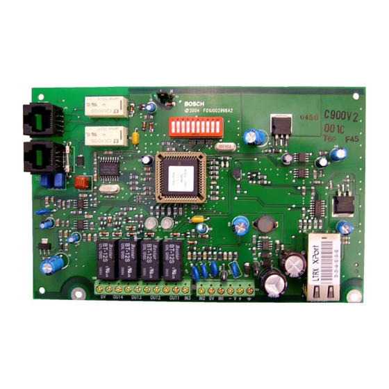
Conettix C900V2 | Installation Guide | Contents Mounting 1.0 Introduction The C900V2 is static sensitive. Before The Conettix C900V2 Dialer Capture Ethernet Module handling the circuit board, touch earth (referred to as the C900V2) links the digital dialer ground to discharge any static electricity (data output) from a control panel to an Ethernet from your body. -
Page 5: Attaching The Module To The Enclosure Door
Conettix C900V2 | Installation Guide | Contents 2.1.3 Separate Enclosure Mounting Figure 2: Optional Mounting Plate You can mount the C900V2 in a separate enclosure such as the AE2. Refer to Figure 4. Mount the enclosure on a vertical surface before you install the C900V2 because the C900V2 covers one of the mounting holes (9). -
Page 6: Wiring
Conettix C900V2 | Installation Guide | Contents Wiring Figure 5: Wiring to a DS7400Xi in the Same Enclosure 1 – C900V2 5 – Battery 2 – To LAN or WAN port 6 – EOL resistor for the control panel, attached to terminals 3 –... -
Page 7: Input Functions
Connect Output 1 from the C900V2 to a 24-hour zone on the control panel. This 24-Hour Zone Alarm report enables the digital dialer, if used, to indicate or sound a failure if the C900V2 CPU fails. Bosch Security Systems, Inc. | 8/08 | F01U087780-01... -
Page 8: Ethernet Connection
Conettix C900V2 | Installation Guide | 3.0 Setup Ethernet Connection Setting the DIP Switches One of the RJ-45 jacks connects the C900V2 to A ten-position DIP switch programs the C900V2. the Ethernet Network (LAN or WAN). The programming depends on the application and dialer format of the control panel connected to the The connector pins are listed in Table 3. -
Page 9: Digital Dialer Protocol (Dip Switches 1 Through 4, And 10)
Conettix C900V2 | Installation Guide | 3.0 Setup Table 4: Digital Dialer Protocol (DIP Switches 1 through 4, and 10) DIP Switches Dialer Format of Host Alarm Panel Radionics Modem IIe and Modem IIIa Radionics Modem II DTMF* DTMF* (where dialer retransmits quickly) -
Page 10: Leds
Conettix C900V2 | Installation Guide | 3.0 Setup Table 5: DIP Switches 5 through 9 Switch State Function Enable auto Fallback Mode after detecting an intercept error. Disable auto Fallback Mode after detecting an intercept error. Hang-ups do not cause Fallback Mode. -
Page 11: Table 3: Table
Conettix C900V2 | Installation Guide | 3.0 Setup Table 6: System LED Functions Color State Function None No power. Green Solid C900V2 failed. Flashing (5 Hz) The receiver is responding normally. Solid C900V2 failed. Flashing (5 Hz) The receiver is not responding. -
Page 12: Dialer Interaction
Conettix C900V2 | Installation Guide | 3.0 Setup Dialer Interaction Fallback Mode Table 8 shows the conditions causing the C900V2 In fallback operation, the C900V2 connects the to change to Fallback Mode. The C900V2 returns PSTN directly to the dialer, bypassing itself from to Intercept Mode only when all conditions in the the phone circuit. -
Page 13: C900V2 Configuration Setup Instructions
Conettix C900V2 | Installation Guide | 4.0 C900V2 Configuration Setup Instructions Figure 10: MAC Address Label Example 4.0 C900V2 Configuration Setup Instructions Dynamic Host Configuration Protocol (DHCP) The receiver can communicate with a C900V2 that has an IP address dynamically assigned by a DHCP server on the network. -
Page 14: Using Telnet To Finish The Configuration
Conettix C900V2 | Installation Guide | 4.0 C900V2 Configuration Setup Instructions The IP and MAC addresses in this Figure 11: ARP Table procedure are examples and are not the same as those for your C900V2. 1. Select Start Run. The Run dialog box appears. -
Page 15: Starting Windows 2000/Xp Telnet
Conettix C900V2 | Installation Guide | 4.0 C900V2 Configuration Setup Instructions After a few seconds, an error message appears. 4. Click OK to clear the message. The Telnet window appears again. 5. Select Connect Remote System. The Connect dialog box appears again. -
Page 16: C900V2 Configuration Setup Instructions Table
Conettix C900V2 | Installation Guide | 4.0 C900V2 Configuration Setup Instructions 5. Press [ENTER]. The Setup Mode information Table 9: Netmask Address appears. Host Netmask Host Netmask Bits Bits 255.255.255.254 255.254.0.0 255.255.255.252 255.252.0.0 255.255.255.248 255.248.0.0 255.255.255.240 255.240.0.0 255.255.255.224 255.224.0.0 255.255.255.192 255.192.0.0... - Page 17 Conettix C900V2 | Installation Guide | 4.0 C900V2 Configuration Setup Instructions 15. Type the Port Number for the receiver and press [ENTER]. If you want to enable encryption, continue with the next step. If not, go to step 27. If you enable encryption on the C900V2, you must enable encryption on the D6680 with the same key.
-
Page 18: Anti-Substitution Protection
Conettix C900V2 | Installation Guide | 5.0 Anti-Substitution Protection 28. At the C:\> prompt, type ping <IP Address> and press [ENTER]. 5.0 Anti-Substitution Four reply messages are received, confirming Protection the C900V2 is communicating on the network. 1. Remove power from the C900V2. -
Page 19: Ul Standard 1610 And Ulc S304 Intrusion System Installations
Conettix C900V2 | Installation Guide | 6.0 UL Standard 1610 and ULC S304 Intrusion System Installations 6.0 UL Standard 1610 and 5. Connect Output 1 from the C900V2 to a 24-hour zone on the control panel. ULC S304 Intrusion This enables the control panel to locally System Installations annunciate a C900V2 CPU failure. -
Page 20: Figure 12: C900V2 And Generic Control Panel In Separate Enclosures (Ul Standard 1610, With Or Without Telephone Line)
Conettix C900V2 | Installation Guide | 6.0 UL Standard 1610 and ULC S304 Intrusion System Installations Figure 12: C900V2 and Generic Control Panel in Separate Enclosures (UL Standard 1610, with or without Telephone Line) PANEL TELCO 1 – Optional telephone line 6 –... -
Page 21: Connection Sequence - C900V2 And
Conettix C900V2 | Installation Guide | 6.0 UL Standard 1610 and ULC S304 Intrusion System Installations Table 10: Connection Sequence – C900V2 and Generic Control Panel in Separate Enclosures (UL Standard 1610, with or without Telephone Line) C900V2 Connection Control Panel Connection... -
Page 22: Protected Premises Control Panel With Digital Table 12: Dialer Backup
Conettix C900V2 | Installation Guide | 6.0 UL Standard 1610 and ULC S304 Intrusion System Installations 6. Connect Output 2 from the C900V2 to a Protected Premises Control 24-our zone on the control panel. Panel with Digital Dialer Backup This tests the digital dialer if the network 1. -
Page 23: Ul Standard 864 For Fire System Installations
Conettix C900V2 | Installation Guide | 7.0 UL Standard 864 for Fire System Installations 4. Program the control panel to send a daily test 7.0 UL Standard 864 for Fire signal through the digital dialer. This tests the connection from the System Installations control panel to the C900V2. -
Page 24: Figure 13: C900V2 And Generic Control Panel In Separate Enclosures (Ul Standard 864)
Conettix C900V2 | Installation Guide | 7.0 UL Standard 864 for Fire System Installations Figure 13: C900V2 and Generic Control Panel in Separate Enclosures (UL Standard 864) PANEL TELCO 1 – Optional telephone line 7 – Host control panel 2 – C900V2 8 –... -
Page 25: Connection Sequence - C900V2 And Generic Control Panel In Separate Enclosures (Ul Standard 864)
Conettix C900V2 | Installation Guide | 7.0 UL Standard 864 for Fire System Installations Table 11: Connection Sequence – C900V2 and Generic Control Panel in Separate Enclosures (UL Standard 864) C900V2 Connection Control Panel Connection Other Connection RJ-45 PANEL connector... -
Page 26: 8.0 Specifications
Conettix C900V2 | Installation Guide | 8.0 Specifications 8.0 Specifications Table 12: Specifications Voltage Range 12 VDC to 24 VDC, nominal Current 280 mA, maximum Dimensions 17.8 cm x 11.4 cm (7 in. X 4.5 in.) Operating 0º C to 49º C (32º F to 120º F) -
Page 27: Appendix : C900V2 Compatible Data Formats
Conettix C900V2 | Installation Guide | Appendix : C900V2 Compatible Data Formats Appendix : C900V2 Compatible Data Formats Table 13: Compatible Central Station Receiver Formats Compatible Receiver Formats Radionics Radionic SIA Bell Pulse DTMF Receive Modem s BFSK 103, 110... - Page 28 Bosch Security Systems, Inc. 130 Perinton Parkway Fairport, NY 14450-9199 (800) 289-0096 © 2008 Bosch Security Systems, Inc. F01U087780-01...
Need help?
Do you have a question about the Conettix C900V2 and is the answer not in the manual?
Questions and answers