Table of Contents
Advertisement
Quick Links
- 1 Bowflex Power Pro Parts Reference Guide
- 2 Power Pro Assembly Instructions
- 3 Parts Reference Guide
- 4 Assembling the Power Pro
- 5 Leg Extension Attachment Assembly Instructions
- 6 Installing the Leg Extension Attachment
- 7 Lat Pulldown Attachment Assembly Instructions
- Download this manual
See also:
Owner's Manual
Advertisement
Table of Contents

Related Manuals for Bowflex Power Pro

Summary of Contents for Bowflex Power Pro
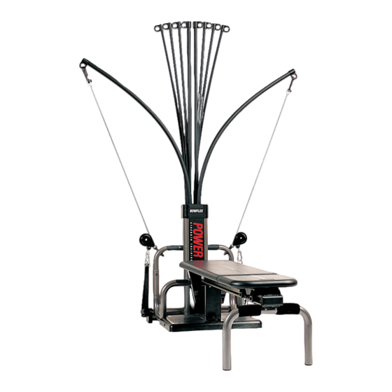
- Page 1 ® BOWFLEX Power Pro ASSEMBLY MANUAL Includes Instructions for Bowflex Power Pro Attachments and Upgrades.
-
Page 2: Table Of Contents
Bowflex Power Pro. The warranty does not cover commercial use or Bowflex, Inc. will repair any Bowflex that proves to be a defect in materials misuse & abuse by the consumer. To make this warranty or workmanship. - Page 3 (to hold the bolt while tightening with other), a rubber mallet (for step #5) and a phillips head (+) screw driver. Please follow these assembly instructions carefully. If you experience any difficulty, please call a Bowflex customer service representative and ask for assistance. 1-800-269-3539. Bowflex Power Pro Parts Reference Guide Name: 1/4"...
-
Page 4: Parts Reference
BOWFLEX Before each use of the ® equipment, check all fasteners, POWER PRO snap hooks, cables and pulley functions. Tighten and fasten as needed. Check pulleys and Parts Reference Guide cables for wear and function. Rod Cap Power Rods Incline... -
Page 5: Assembling The Power Pro
Assembling the Power Pro Step 1: Locate the Rear Leg and Seat Rail. Components for this assembly are in Boxes 2 and 3 Take two 3/8” x 3/4” square head bolts and place them through holes on the Rear Leg Bolt Keeper. Take that assembly and slide it into the Seat Rail channel, starting on the end closest to the warning label. -
Page 6: Assembly Instructions
Step 2: Components for this assembly Locate Seat and Bench and are in Boxes 2 and 3 separate from one another. They are connected by a Quick Release Hinge. See illustration 2a at right. Bench Seat The seat slides onto the Seat Rail by aligning the wheels on the Seat with the channels along the sides of the Seat Rail. - Page 7 Step 4: Components for this Locate the Vertical Mainframe. assembly are in Box 2 Attach U-Bar portion of Pulley Frame to the Vertical Main Frame with the 3/8" x 2 1/2" Hex Head Bolt. Use the 3/8" x 4" Hex Head Bolt to secure the lower portion of the Pulley Frame.
- Page 8 Step 6: Components for this Now locate the Bench. Turn Bench upside down. assembly are in Box 2 Place the Bench Cup between the two hinges. #14 Screw Secure with a #14 Screw. Bench Cup Step 7: Now locate the Incline Support Bracket.
- Page 9 Step 8: Components for this Place Bench onto the Bowflex. assembly are in Box 2 Unwrap Cables and Pulleys. Locate Nonskid Pads. Remove paper backing to expose the adhesive surface. Adhere Nonskid Pads to Pulley Frame as shown. Note: If you installed a CHEST BAR Attachment, please go to page 16, step 8.
-
Page 10: Leg Extension Attachment
Thank you for choosing the Bowflex Leg Extension Attachment. This attachment comes complete in one box, with everything you need to assemble your new accessory. Before you begin, you will need a crescent wrench, a 5/16" open end wrench. (It is helpful to have the crescent wrench to hold one end of a bolt while tightening with the other). -
Page 11: Installing The Leg Extension Attachment
Installing the Leg Extension Attachment Components for this assembly are in a box labeled Leg Extension Attachment Step 1: Step 2: Rotate Pivot Arm Bracket Secure Pivot Arm Bracket by inserting one 5/16" x 2" Hex Head as indicated. Bolt through indicated hole on Bracket and tighten with one 5/16"... - Page 12 Thread cable through Pulley and Hook Loop around metal tube on each side as indicated below. Slide Foam Pads onto metal tube and insert End Caps. Use Snap Hook to fasten Leg Extension Cables to Bowflex Cables. “L” Pin Pulleys...
-
Page 13: Chest Bar Attachment
Assembly Instructions attachment may or may not be included. Thank you for choosing the Bowflex Chest Bar Attachment. This attachment comes complete in one box, with everything you need to assemble your new accessory. Before you begin, you will need a crescent wrench, a 9/16"... - Page 14 Chest Bar Assembly Instructions Components for this assembly are in a box labeled Chest Bar Attachment Step 1: Slide Seat to end of seat rail and lower to flat position. Step 2: Vertical Main Frame Remove indicated bolts going through pulley frame and Vertical Main Frame.
- Page 15 Tighten securely. Note: Once you finish installing your chest bar, go back to page 8, step 4 and continue assembling your Bowflex. Step 7: Replace the Vertical Main Frame with Rod Pack that you removed in step two. Secure with bolts that were set aside.
- Page 16 The Chest Bar has two positions. Standard Position is the way it came, approximately the same width as the U-Bar that was previously attached to your Power Pro. Extended Position for enhancing your chest and shoulder exercises. To extend your bar, simply un-...
-
Page 17: Lat Pulldown Attachment
Lat Pulldown Attachment The Lat Pulldown Attachment is an optional attachment. Depending on the machine and accessories you ordered, this Assembly Instructions attachment may or may not be included. Components for this assembly are in a box labeled Lat Pulldown Attachment Box Contents 1 Cross Bar Name: 1/4"... - Page 18 Installing The Lat Pulldown Attachment Components for this assembly are in a box labeled Lat Pulldown Attachment Step 1: Remove the long portion of the Bench. Step 2: Place the cross bar so the curved ends are facing downward and they rest on the bottom of the pulley frame.
- Page 19 Flanges Step 5: Secure the Main Frame Brackets to your Bowflex by sliding the long Square Head Bolt through the holes on the end of the brackets. Make sure that the bolts’ heads are seated in the square holes. Tighten Wing Nuts onto end of bolts and tighten...
- Page 20 Components for this assembly are in a box labeled Lat Pulldown Attachment Step 6: Upper Main Frame Locate Upper Main Frame. Slide upper half onto lower half. Insert the 1/4" x 3 1/2" Hex Head Bolts through holes and tighten with 1/4" Lock Nuts. 1/4"...
- Page 21 Replace Bench. Insert Cables through the Pulleys and attach the end of Cable, without the Rubber Stop, to the regular Bowflex Cable by removing Hand Grips and using Snap Hooks to attach the loop end of the Cable. Do this on both sides. Hook up the 30 pound Power Rods on each side at this time.
-
Page 22: Squat Attachment
Cable Ends. Then, attach small Cable Ends to Power Rod Cables. Caution: Be sure to remove Squat Plate before folding and transporting the Bowflex. • Always wear shoes with a non-skid sole when using the Squat Attachment. • Never adjust cable travel and tension with Expansion Chain to the degree that tension is applied in such a manner that would be hazardous. - Page 23 BENT OVER ROW DEAD LIFT FINISH START FINISH START Keep back flat - do not arch. Keep back flat - do not arch. Lift with your legs not Keep your knees bent and head up. your back. Keep your knees bent and your head up. BARBELL BICEPS CURL SINGLE ARM BICEPS CURL START...
- Page 24 Installing the Foot Harness Bowflex has specially designed a Foot Harness which securely holds your foot to the Pulley Frame while you row vigorously to obtain your maximum aerobic workout. Just strap foot to the Pulley Frame with the straps located underneath the foot. Secure them tightly so there is no gapping space between the Pulley Frame and your foot.
- Page 25 Pull it through the Ring and fold excess back and attach with velcro. Assembling Your Bowflex T-Bar Your t-bar was shipped fully assembled with the metal bar resting in the loops of the nylon strap. If, however, the bar and the nylon strap separated during shipping, follow these instructions for reassembly.
- Page 26 Expanding Your Bowflex With Extra Power Rods To expand your Bowflex from 210 lbs to 310 lbs: Step 1: Remove your Power Rod pack by removing the four screws on the back of the Base. To expand your Bowflex from 310 lbs.
- Page 27 The Nautilus Group. Inc. The Nautilus Group, Inc. 1400 N.E. 136th Ave., Vancouver, WA 98684 Bowflex and the Bowflex logo are registered trademarks of The Nautilus Group, Inc. — a NYSE-listed company © 2002,The Nautilus Group, Vancouver, WA 98684 PN80159...
Need help?
Do you have a question about the Power Pro and is the answer not in the manual?
Questions and answers