Table of Contents
Advertisement
61700100G1-34F
June 2013
NetVanta 6310/6330 Series
Hardware Installation Guide
1702100G1
NetVanta 6310
47006332G1
NetVanta 6330 (8 FXS)
47006334G1
NetVanta 6330 (16 FXS)
47006336G1
NetVanta 6330 (24 FXS)
47006337G1
NetVanta 6330 (16 FXS/8 FXO)
1700101G1
NetVanta SHDSL, Annex A NIM2
1700101G2
NetVanta SHDSL Annex B NIM2
1700102G1
NetVanta Quad FXS VIM2
1700103G1
NetVanta Quad SHDSL EFM, Annex A NIM2
1700103G2
NetVanta Quad SHDSL EFM, Annex B NIM2
1700105G1
NetVanta Quad FXO VIM2
1700106G1
NetVanta Quad T1/E1 EFM NIM2
1700107G1
NetVanta Ethernet NIM2
1700108G1
NetVanta Octal FXS VIM2
1700109G1
NetVanta Octal FXO VIM2
1700111G1
NetVanta Quad FXS/FXO VIM2
1700112G1
NetVanta Quad BRI S/T VIM2
1700114G1
NetVanta ADSL2+ Annex A NIM2
1200819E1
CompactFlash
®
1 GB
Advertisement
Chapters
Table of Contents

Subscribe to Our Youtube Channel
Related Manuals for ADTRAN 6310


Summary of Contents for ADTRAN 6310
- Page 1 NetVanta 6310/6330 Series Hardware Installation Guide 1702100G1 NetVanta 6310 47006332G1 NetVanta 6330 (8 FXS) 47006334G1 NetVanta 6330 (16 FXS) 47006336G1 NetVanta 6330 (24 FXS) 47006337G1 NetVanta 6330 (16 FXS/8 FXO) 1700101G1 NetVanta SHDSL, Annex A NIM2 1700101G2 NetVanta SHDSL Annex B NIM2...
- Page 2 To the Holder of the Manual The contents of this manual are current as of the date of publication. ADTRAN reserves the right to change the contents without prior notice. In no event will ADTRAN be liable for any special, incidental, or consequential damages or for commercial losses even if ADTRAN has been advised thereof as a result of issue of this publication.
- Page 3 NetVanta 6310/6330 Series Hardware Installation Guide Conventions Conventions Notes provide additional useful information. Cautions signify information that could prevent service interruption or damage to the equipment. Warnings provide information that could prevent injury or endangerment to human life. 61700100G1-34F Copyright © 2013 ADTRAN, Inc.
- Page 4 Safety Instructions NetVanta 6310/6330 Series Hardware Installation Guide Safety Instructions When using your telephone equipment, please follow these basic safety precautions to reduce the risk of fire, electrical shock, or personal injury: 1. Do not use this product near water, such as a bathtub, wash bowl, kitchen sink, laundry tub, in a wet basement, or near a swimming pool.
- Page 5 Advance notification and the opportunity to maintain uninterrupted service are given. 4. If experiencing difficulty with this equipment, please contact ADTRAN for repair and warranty information. The telephone company may require this equipment to be disconnected from the network until the problem is corrected, or it is certain the equipment is not malfunctioning.
- Page 6 FCC Radio Frequency Interference Statement NetVanta 6310/6330 Series Hardware Installation Guide FCC Radio Frequency Interference Statement This equipment has been tested and found to comply with the limits for a Class B digital device, pursuant to Part 15 of the FCC rules. These limits are designed to provide reasonable protection against harmful interference when the equipment is operated in a commercial environment.
- Page 7 Denial of Service (DoS) attacks, loss or theft of data, and the unauthorized or illegal use of said equipment. ADTRAN OFFERS NO WARRANTIES, EITHER EXPRESSED OR IMPLIED, REGARDING THE PREVENTION, DETECTION, OR DETERRENCE OF TOLL FRAUD, NETWORKING ATTACKS, OR UNAUTHORIZED, ILLEGAL, OR IMPROPER USE OF ADTRAN EQUIPMENT OR SOFTWARE.
- Page 8 Service and Warranty NetVanta 6310/6330 Series Hardware Installation Guide Copyright © 2013 ADTRAN, Inc. 61700100G1-34F...
-
Page 9: Table Of Contents
NetVanta 6310/6330 Series Front Panel LEDs ........ - Page 10 Table of Contents NetVanta 6310/6330 Series Hardware Installation Guide Copyright © 2013 ADTRAN, Inc. 61700100G1-34F...
- Page 11 NetVanta 6310 Front Panel Layout ........
- Page 12 List of Figures NetVanta 6310/6330 Series Hardware Installation Guide Copyright © 2013 ADTRAN, Inc. 61700100G1-34F...
- Page 13 NetVanta 6310/6330 Series Front Panel LEDs ........
- Page 14 List of Tables NetVanta 6310/6330 Series Hardware Installation Guide Copyright © 2013 ADTRAN, Inc. 61700100G1-34F...
-
Page 15: Introduction
INTRODUCTION The NetVanta 6310/6330 Series includes the NetVanta 6310 primary rate interface (PRI), and the NetVanta 6330 Series (8 FXS, 16 FXS, 24 FXS, and 16 FXS + 8 FXO models) analog multiservice access gateways. In this document, the term NetVanta means all of the units collectively. If a statement only applies to one particular unit, the text refers to that unit individually. -
Page 16: Physical Description
Series: the NetVanta 6310 PRA/PRI/E1/T1 unit. There are four models in the NetVanta 6330 Analog Series: the 8 FXS model, 16 FXS model, 24 FXS model, and 16 FXS + 8 FXO model. All NetVanta 6310/6330 Series models include a modular wide area network (WAN) interface(s), two 10/100Base-T Ethernet ports, an integrated router, stateful inspection firewall, and transparent Session Initiation Protocol (SIP) proxy. -
Page 17: Netvanta 6310 Rear Panel Design
NetVanta 6310/6330 Series Hardware Installation Guide Physical Description NetVanta 6310 Rear Panel Design The NetVanta 6310 rear panel is shown below. ETH 0/1 100-240 VAC 50/60 Hz SHDSL EFM ANNEX B PRI 0/1 SLOT 2 ETH 0/2 SLOT 1 Figure 2. NetVanta 6310 Rear Panel Layout... -
Page 18: Netvanta 6330 Series Front Panel Design
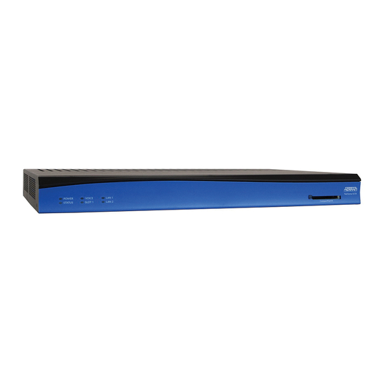
Physical Description NetVanta 6310/6330 Series Hardware Installation Guide NetVanta 6330 Series Front Panel Design The NetVanta 6330 front panel is shown below. Table 1 on page 19 describes all of the LEDs. NetVanta 6330 Front Panel Features Status LEDs The status LEDs are located on the lower left side of the unit. The STAT LED indicates the unit’s... -
Page 19: Netvanta 6310/6330 Series Front Panel Leds
Supplying Power to the Unit on page 40 for connection details. NetVanta 6310/6330 Series Front Panel LEDs Table 1 describes the front panel LEDs. Table 1. NetVanta 6310/6330 Series Front Panel LEDs Color Indication STATUS Unit is not receiving power. Green (flashing) - Page 20 Physical Description NetVanta 6310/6330 Series Hardware Installation Guide Table 1. NetVanta 6310/6330 Series Front Panel LEDs (Continued) Color Indication SLOT 1/SLOT 2 All ports are inactive or administratively disabled. (Analog Modules) Green (solid) VIM2 is off-hook. Green (flashing) VIM2 is ringing.
-
Page 21: Features And Specifications
• Supports up to 24 analog ports and one NIM2/VIM2 option slot (NetVanta 6330 Analog Series models) • Supports a single PRA/PRI/E1/T1 interface and two NIM2/VIM2 option slots (NetVanta 6310 PRI model) • Supports a dual auto MDI/MDIX 10/100Base-T Ethernet interface Ethernet Features •... - Page 22 Features and Specifications NetVanta 6310/6330 Series Hardware Installation Guide Voice Features • Supports three-way conferencing • Supports caller ID, message waiting (both frequency shift keying (FSK) and voltage), and stutter dial tone • Fax and analog modem compatible (V.90) •...
-
Page 23: Option Modules
Option Modules OPTION MODULES The NetVanta 6310 Series supports several option modules designed to meet a variety of networking requirements. The option modules include plug-in network and voice interface modules (NIMs/VIMs). NIM2s/VIM2s are cards that plug directly into the option module slot located on the rear of the base unit. These cards provide the following types of interfaces: •... -
Page 24: Network Interface Modules
Option Modules NetVanta 6310/6330 Series Hardware Installation Guide Network Interface Modules NetVanta SHDSL, Annex A NIM2 (P/N 1700101G1) The NetVanta SHDSL, Annex A NIM2 (shown in Figure 5) provides a SHDSL 2-wire or 4-wire interface for the NetVanta 6310/NetVanta 6330 Series. See Table A-8 on page 45 for the SHDSL EFM connector pinouts. -
Page 25: Figure 6. Netvanta Shdsl, Annex B Nim2
NetVanta 6310/6330 Series Hardware Installation Guide Option Modules NetVanta SHDSL, Annex B NIM2 (P/N 1700101G2) The NetVanta SHDSL, Annex B NIM2 (shown in Figure 6) provides a SHDSL 2-wire or 4-wire interface for the NetVanta 6310/NetVanta 6330 Series. See Table A-9 on page 45 for the SHDSL connector pinouts. -
Page 26: Figure 7. Netvanta Quad Shdsl Efm, Annex A Nim2
NetVanta Quad SHDSL EFM, Annex A NIM2 (P/N 1700103G1) The NetVanta Quad SHDSL EFM, Annex A NIM2 (shown in Figure 7) provides a WAN-SHDSL EFM interface for the NetVanta 6310/NetVanta 6330 Series. See Table A-8 on page 45 Table A-9 on page 45 the SHDSL EFM connector pinouts. -
Page 27: Figure 8. Netvanta Quad Shdsl Efm, Annex B Nim2
NetVanta Quad SHDSL EFM, Annex B NIM2 (P/N 1700103G2) The NetVanta Quad SHDSL EFM, Annex B NIM2 (shown in Figure 8) provides a WAN-SHDSL EFM interface for the NetVanta 6310/NetVanta 6330 Series. See Table A-8 on page 45 Table A-9 on page 45 the SHDSL EFM connector pinouts. -
Page 28: Figure 9. Netvanta Quad T1/E1 Efm Nim2
Option Modules NetVanta 6310/6330 Series Hardware Installation Guide NetVanta Quad T1/E1 EFM NIM2 (P/N 1700106G1) The NetVanta Quad T1/E1 EFM NIM2 (shown in Figure 9) provides a WAN-T1/E1 EFM interface for the NetVanta 6310/NetVanta 6330 Series. See Table A-10 on page 46 for the T1/E1 connector pinouts. -
Page 29: Figure 10. Netvanta Ethernet Nim2
NetVanta 6310/6330 Series Hardware Installation Guide Option Modules NetVanta Ethernet NIM2 (P/N 1700107G1) The NetVanta Ethernet NIM2 (shown in Figure 10) provides an Ethernet interface for the NetVanta 6310/NetVanta 6330 Series. See Table A-7 on page 45 for the Ethernet module pinouts. -
Page 30: Figure 11. Netvanta Quad Bri S/T Nim2
Option Modules NetVanta 6310/6330 Series Hardware Installation Guide NetVanta Quad BRI S/T NIM2 (P/N 1700112G1) The NetVanta Quad BRI S/T NIM2 (shown in Figure 11) provides a BRI S/T interface for the NetVanta 6310/NetVanta 6330 Series. See Table A-11 on page 46 for the Quad BRI S/T connector pinouts. -
Page 31: Figure 12. Netvanta Adsl2+ Annex A Nim2
NetVanta ADSL2+ Annex A NIM2 (P/N 1700114G1) The NetVanta ADSL2+ Annex A NIM2 (see Figure 12) adds ADSL capability to the NetVanta 6310/6330 Series. The module provides a single ADSL, ADSL2, or ADSL2+ network interface to support rates up to 25 Mbps. See Figure A-6 on page 45 for the ADSL2+ pinouts. -
Page 32: Voice Interface Modules
Voice Interface Modules NetVanta Quad FXS VIM2 (P/N 1700102G1) The NetVanta Quad FXS VIM2 (see Figure 13) adds voice capability to the NetVanta 6310/NetVanta 6330 Series. See Table A-12 on page 46 for the foreign exchange service (FXS) connector pinouts. -
Page 33: Figure 14. Netvanta Quad Fxo Vim2
Option Modules NetVanta Quad FXO VIM2 (P/N 1700105G1) The NetVanta Quad FXO VIM2 (see Figure 14) adds voice capability to the NetVanta 6310/NetVanta 6330 Series. See Table A-12 on page 46 for the foreign exchange office (FXO) connector pinouts. Figure 14. NetVanta Quad FXO VIM2... -
Page 34: Figure 15. Netvanta Octal Fxs Vim2
NetVanta 6310/6330 Series Hardware Installation Guide NetVanta Octal FXS VIM2 (P/N 1700108G1) The NetVanta Octal FXS VIM2 (see Figure 15) adds voice capability to the NetVanta 6310/NetVanta 6330 Series. See Table A-12 on page 46 for the FXS connector pinouts. -
Page 35: Figure 16. Netvanta Octal Fxo Vim2
Option Modules NetVanta Octal FXO VIM2 (P/N 1700109G1) The NetVanta Octal FXO VIM2 (see Figure 16) adds voice capability to the NetVanta 6310/NetVanta 6330 Series. See Table A-12 on page 46 for the FXO connector pinouts. Figure 16. NetVanta Octal FXO VIM2... -
Page 36: Figure 17. Netvanta Quad Fxs/Fxo Vim2
NetVanta 6310/6330 Series Hardware Installation Guide NetVanta Quad FXS/FXO VIM2 (P/N 1700111G1) The NetVanta Quad FXS/FXO VIM2 (see Figure 17) adds voice capability to the NetVanta 6310/NetVanta 6330 Series. See Table A-12 on page 46 for the FXS/FXO connector pinouts. -
Page 37: Unit Installation
ADTRAN unit to Ethernet cables that run outside the building, ADTRAN's Ethernet Port Protection Device (EPPD) (P/N 1700502G1) must be connected between the unit and the outside plant cable. Use of any Ethernet protector other than ADTRAN's for this purpose will void the user's warranty. -
Page 38: Mounting Options
Unit Installation NetVanta 6310/6330 Series Hardware Installation Guide Mounting Options The unit may be installed in rackmount, wallmount, or tabletop configurations. The following sections provide step-by-step instructions for rack mounting and wall mounting. Rack Mounting the NetVanta The NetVanta is a 1U-high, rack-mountable unit that can be installed into a 19-inch equipment rack. The following steps guide you in mounting the NetVanta into a rack. -
Page 39: Figure 18. Wallmount Installation
Decide on a location for the NetVanta, keeping in mind that the unit needs to be mounted at or below eye-level so that the LEDs are viewable. The NetVanta 6310 can only be wall mounted with the front panel facing to the right (see Figure 18). -
Page 40: Supplying Power To The Unit
NetVanta 6310/6330 Series Hardware Installation Guide Supplying Power to the Unit The NetVanta 6310/6330 Series units come equipped with an auto-sensing 100 to 240 VAC, 50/60 Hz power supply for connecting to a properly grounded power receptacle. (A detachable power cable with a grounded, three-prong plug comes with the shipment.) To power this unit, connect the power cable to an appropriate AC... -
Page 41: Installing Network And Voice Interface Modules
NetVanta 6310/6330 Series Hardware Installation Guide Unit Installation Installing Network and Voice Interface Modules The NIM2s/VIM2s are installed into the rear panel option module slots. The following table lists the installation steps. Also, see Figure 19 below. For NetVanta modules with outside plant connections, ensure that all cables are removed from the module before installing or removing it from the NetVanta chassis. -
Page 42: Installing A Compactflash Card
NetVanta 6310/6330 Series Hardware Installation Guide Installing a CompactFlash Card CompactFlash slot supports only the ADTRAN-provided 1 GB CompactFlash card. Follow these instructions when installing a card. The CompactFlash card is hot-swappable, and can be inserted or removed while power is applied to the unit. -
Page 43: Appendix A. Connector Pin Definitions
Name Description Transmit Positive Transmit Negative Receive Positive 4, 5 — Unused Receive Negative 7, 8 — Unused Table A-3. PRI Connector Pinouts Name Description Ring — Unused Ring 6 - 8 — Unused 61700100G1-34E Copyright © 2011 ADTRAN, Inc. -
Page 44: Table A-4. Fxo Connector Pinouts
Appendix A NetVanta 6310/6330 Series Hardware Installation Guide Table A-4. FXO Connector Pinouts Name Description 1, 2 — Unused Ring Ring lead of the 2-wire interface Tip lead of the 2-wire interface 5, 6 — Unused Table A-5. VOICE Connector Pinouts... -
Page 45: Table A-6. Adsl2+ Pinouts
NetVanta 6310/6330 Series Hardware Installation Guide Appendix A Network Interface Module Pinouts Table A-6. ADSL2+ Pinouts Name Description 1, 2 — Unused Network–Ring Network–Tip 5, 6 — Unused Table A-7. Ethernet Module Pinouts Name Description Transmit Positive Transmit Negative Receive Positive 4, 5 —... -
Page 46: Table A-11. Bri S/T Module Pinouts
Appendix A NetVanta 6310/6330 Series Hardware Installation Guide Table A-10. T1/E1 EFM (Ports 1 through 4) Pinouts Name Description RX Ring Receive RX Tip Receive — Unused TX Ring Transmit TX Tip Transmit Table A-11. BRI S/T Module Pinouts Name...
Need help?
Do you have a question about the 6310 and is the answer not in the manual?
Questions and answers