
Subscribe to Our Youtube Channel
Related Manuals for ADTRAN NetVanta 6240 Series


Summary of Contents for ADTRAN NetVanta 6240 Series
- Page 1 NetVanta 6240/6250 Series IP Business Gateways Hardware Installation Guide 61700202G1-34B August 2013...
- Page 2 To the Holder of the Manual The contents of this manual are current as of the date of publication. ADTRAN reserves the right to change the contents without prior notice. In no event will ADTRAN be liable for any special, incidental, or consequential damages or for commercial losses even if ADTRAN has been advised thereof as a result of issue of this publication.
- Page 3 NetVanta 6240/6250 Series HIG Conventions Conventions Notes provide additional useful information. Cautions signify information that could prevent service interruption or damage to the equipment. Warnings provide information that could prevent injury or endangerment to human life. 61700202G1-34B Copyright © 2013 ADTRAN, Inc.
- Page 4 Safety Instructions NetVanta 6240/6250 Series HIG Safety Instructions When using your telephone equipment, please follow these basic safety precautions to reduce the risk of fire, electrical shock, or personal injury: 1. Do not use this product near water, such as a bathtub, wash bowl, kitchen sink, laundry tub, in a wet basement, or near a swimming pool.
- Page 5 Advance notification and the opportunity to maintain uninterrupted service are given. 4. If experiencing difficulty with this equipment, please contact ADTRAN for repair and warranty information. The telephone company may require this equipment to be disconnected from the network until the problem is corrected, or it is certain the equipment is not malfunctioning.
- Page 6 Denial of Service (DoS) attacks, loss or theft of data, and the unauthorized or illegal use of said equipment. ADTRAN OFFERS NO WARRANTIES, EITHER EXPRESSED OR IMPLIED, REGARDING THE PREVENTION, DETECTION, OR DETERRENCE OF TOLL FRAUD, NETWORKING ATTACKS, OR UNAUTHORIZED, ILLEGAL, OR IMPROPER USE OF ADTRAN EQUIPMENT OR SOFTWARE.
-
Page 7: Table Of Contents
NetVanta 6240 Series ........ - Page 8 Table of Contents NetVanta 6240/6250 Series HIG Copyright © 2013 ADTRAN, Inc. 61700202G1-34B...
- Page 9 NetVanta 6240 Front Panel Layout ........
- Page 10 List of Figures NetVanta 6240/6250 Series HIG Copyright © 2013 ADTRAN, Inc. 61700202G1-34B...
- Page 11 Table A-1. VOICE Connector Pinouts (NetVanta 6240) ........
- Page 12 List of Tables NetVanta 624050 Series HIG Copyright © 2013 ADTRAN, Inc. 61700202G1-34B...
-
Page 13: Introduction
Supplying DC Power to the NetVanta 6250 on page 27 • Optional Battery Backup Unit (P/N 1175044L1/L2) on page 29 For information on NetVanta 6240/6250 configuration for a specific application, refer to the configuration guides provided on the ADTRAN Support Community. -
Page 14: Physical Description
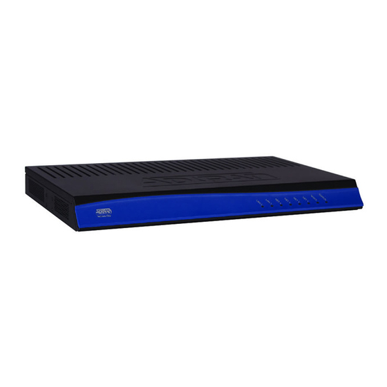
There are several models in the NetVanta 6240 Series that can provide various combinations up to 24 FXS interfaces, up to 10 FXO interfaces, and up to 60 channels of VoIP. All NetVanta 6240 Series models include four modular T1 wide area network (WAN) interfaces, two 10/100Base-T Ethernet ports, an integrated router, stateful inspection firewall, and transparent Session Initiation Protocol (SIP) proxy. -
Page 15: Rear Panel Design
LAN is administratively disabled or link is down. Green (solid) The link is up. Amber (flashing) There is activity on the link. Rear Panel Design The NetVanta 6240 Series rear panel is shown below. NET 1 NET 2 NET 3 NET 4 ETH 0/1... - Page 16 The status LED, labeled , is located on the front panel. VOICE The number of circuits used (1 through 24) is dependent on the model NetVanta 6240. FXO interfaces use circuits 17 through 24 depending on the model. FXO Interfaces FXO 0/1...
-
Page 17: Netvanta 6250 Series
Session Initiation Protocol (SIP) proxy. The NetVanta 6250 Series comes equipped with an AC power supply and an onboard battery charger for use with an ADTRAN battery backup unit that can keep the unit running with all interfaces active should the AC power fail. The NetVanta 6250 also comes equipped with a -48 VDC input for DC powering. -
Page 18: Table 2. Netvanta 6250 Front Panel Leds
Physical Description NetVanta 6240/6250 Series HIG Front Panel Features Status LEDs The status LEDs are located on the left side of the front panel. The LED indicates the status of VOICE the voice ports. The LED indicates the unit’s status. The GIG 1 LED indicates the status of STATUS the Gigabit Ethernet port (both fiber and copper). -
Page 19: Rear Panel Design
NetVanta 6240/6250 Series HIG Physical Description Rear Panel Design The NetVanta 6250 Series rear panel is shown below. T1 0/1 T1 0/3 ETH 0/1 ETH 0/3 AC INPUT VOICE GIG 0/1 RTN -48V CRAFT 10/100/1000 DC IN T1 0/2 T1 0/4... - Page 20 Physical Description NetVanta 6240/6250 Series HIG DC Power Connection A DC input connector, labeled DC IN , is provided to power the unit from a -48 VDC power source. Refer to Supplying DC Power to the NetVanta 6250 on page 27 for connection details.
-
Page 21: Product Specifications
NetVanta 6240/6250 Series HIG Product Specifications PRODUCT SPECIFICATIONS The NetVanta 6240 Series products have the following features: • 8, 16, or 24 foreign exchange station (FXS) ports • 16 FXS ports and 8 foreign exchange office (FXO) ports • Optional 1 onboard FXO (RJ-11) interface on the rear panel •... - Page 22 Product Specifications NetVanta 6240/6250 Series HIG The NetVanta 6250 Series products have the following features: • 8, 16, or 24 FXS ports • 16 FXS ports and 9 FXO ports • 1 built-in FXO lifeline on the rear panel (F2 models only) •...
-
Page 23: Unit Installation
ADTRAN unit to Ethernet cables that run outside the building, ADTRAN's Ethernet Port Protection Device (EPPD) (P/N 1700502G1) must be connected between the unit and the outside plant cable. Use of any Ethernet protector other than ADTRAN's for this purpose will void the user's warranty. -
Page 24: Mounting Options
NetVanta 6240/6250 Series unit. This spacing allows the unit to dissipate heat. The design of the NetVanta 6240/6250 Series uses the chassis to distribute heat generated by the unit’s internal cards. This design allows the unit to operate without a cooling fan, ensuring the overall reliability of the unit. - Page 25 Decide on a location for the NetVanta, keeping in mind that the unit needs to be mounted at or below eye-level so that the LEDs are viewable. Warning! The NetVanta 6240/6250 can only be wall mounted with the front panel facing to the right, to the left, or downward (see the example in Figure 5 on page 26).
-
Page 26: Figure 5. Wallmount Installation
Unit Installation NetVanta 6240/6250 Series HIG Figure 5. Wallmount Installation Copyright © 2013 ADTRAN, Inc. 61700202G1-34B... -
Page 27: Supplying Power To The Unit
Unit Installation Supplying Power to the Unit The NetVanta 6240/6250 Series units come equipped with a 120 VAC, 60 Hz power supply for connecting to a properly grounded power receptacle. (A detachable power cable with a grounded, three-prong plug comes with the shipment.) To power this unit, connect the power cable to an appropriate AC power source. -
Page 28: Figure 6. Supplying Dc Power And Grounding The Netvanta 6250
Unit Installation NetVanta 6240/6250 Series HIG Instructions for Connecting DC Power Source to the NetVanta 6250 Step Action Insert the positive terminal of the DC power source into left position of the two-position terminal block (labeled RTN on the NetVanta 6250). Tighten the screw. -
Page 29: Optional Battery Backup Unit (P/N 1175044L1/L2)
Unit Installation Optional Battery Backup Unit (P/N 1175044L1/L2) The ADTRAN battery backup unit (BBU) is an optional device designed as a backup DC power supply for the NetVanta 6240/6250 Series. The BBU connects to the NetVanta 6240/6250 through a 6-foot charge/discharge, 2-conductor wire with a keyed modular plug (included with the BBU). -
Page 30: Figure 7. Wall Mounting The Bbu
Unit Installation NetVanta 6240/6250 Series HIG Wall Mounting the BBU Figure 7 shows the BBU (P/N 1175044L1) mounting dimensions for the NetVanta 6240/6250 Series. Figure 7. Wall Mounting the BBU Install the BBU as follows: Instructions for Wall Mounting the BBU... -
Page 31: Table 3. Bbu Specifications
To order replacement batteries, reference the following part number: 1975044L1 (12 V replacement batteries). ADTRAN is an environmentally friendly company. Therefore, we encourage the proper recycling and handling of the batteries. Federal and state laws prohibit the improper disposal of all lead acid batteries. - Page 32 Unit Installation NetVanta 6240/6250 Series HIG Copyright © 2013 ADTRAN, Inc. 61700202G1-34B...
-
Page 33: Appendix A. Connector Pin Definitions
APPENDIX A. CONNECTOR PIN DEFINITIONS The following tables provide the pin assignments for the base unit. Table A-1. VOICE Connector Pinouts (NetVanta 6240) 50-pin Pins Amphenol Description Connector 1, 26 Circuit 1 FXS 0/1 Ring, Tip 2, 27 Circuit 2... -
Page 34: Table A-2. Voice Connector Pinouts (Netvanta 6250)
Appendix A NetVanta 6240/6250 Series HIG Table A-2. VOICE Connector Pinouts (NetVanta 6250) 50-pin Pins Amphenol Description Connector 1, 26 Circuit 1 FXS 0/1 Ring, Tip 2, 27 Circuit 2 FXS 0/2 Ring, Tip 3, 28 Circuit 3 FXS 0/3 Ring, Tip... -
Page 35: Table A-3. Fxo Connector Pinouts
NetVanta 6240/6250 Series HIG Appendix A Table A-3. FXO Connector Pinouts Name Description 1, 2 — Unused Ring Ring lead of the 2-wire interface Tip lead of the 2-wire interface 5, 6 — Unused Table A-4. T1 Port Pinouts Name Description Receive data from the network–Ring... -
Page 36: Table A-7. Craft Port Pinouts
Appendix A NetVanta 6240/6250 Series HIG Table A-7. CRAFT Port Pinouts Name Description Data Carrier Detect (output) Receive Data (output) Transmit Data (input) Data Terminal Ready (input) Signal Ground Data Set Ready (output) Request to Send (input) Clear to Send (output) —...
Need help?
Do you have a question about the NetVanta 6240 Series and is the answer not in the manual?
Questions and answers