Table of Contents
Advertisement
Quick Links
Advertisement
Table of Contents

Related Manuals for Ericsson HM210DP/DI


Summary of Contents for Ericsson HM210DP/DI
-
Page 1: Adsl Modem
ADSL Modem HM210dp/di User Guide... - Page 2 Abstract This User guide describes how to install and set up the Ericsson ADSL Modem HM210dp/di in a Windows environment, and how to customize its configuration to get the most out of the product. Trademark List Windows...
-
Page 3: Table Of Contents
3.1.3 3.2.1 3.2.2 3.2.3 4.2.1 EN/LZT 108 6492 R2 – October 2003 Introduction About this User Guide About the ADSL Modem HM210d Features Hardware Description and Installation Before You Start Package Contents Subscription for ADSL Service System Requirements Physical Appearance... - Page 4 5.4.2 5.5.1 5.5.2 5.5.3 7.3.1 The Home Page and System View Table Commiting Changes and Rebooting Rebooting the HM210dp/di using Options Quick Configuration Basic Configuration Configuring the ATM Virtual Circuit Adding ATM VCs Modifying ATM VCs Configuring PPP Interfaces Adding PPP Interfaces...
- Page 5 7.3.2 7.3.3 7.3.4 7.3.5 7.3.6 7.4.1 7.4.2 7.4.3 8.5.1 8.5.2 8.5.3 8.5.4 8.5.5 8.5.6 10.1 10.2 10.3 EN/LZT 108 6492 R2 - October 2003 Enabling DHCP Server Mode Configuring Your PCs as DHCP Clients Viewing, Modifying and Deleting Address Pools Excluding IP Addresses from a Pool Viewing Current DHCP Address Assignments Configuring DHCP Relay...
- Page 6 Contents 11.1 11.2 11.2.1 11.2.2 11.2.3 11.2.4 11.2.5 11.3 12.1 12.2 12.3 12.4 12.5 12.5.1 12.6 14.1 14.2 14.3 14.4 14.4.1 14.4.2 14.4.3 15.1 15.2 Configuring Firewall Settings Global Firewall Settings Configuring IP Filters Viewing Your IP Filter Configuration Configuring IP Filter Global Settings Creating IP Filter Rules Viewing IP Filter Statistics Managing Current IP Filter Sessions...
- Page 7 15.2.1 15.2.2 15.2.3 15.2.4 15.2.5 15.2.6 15.3 15.3.1 15.3.2 15.3.3 15.3.4 15.3.5 15.3.6 15.3.7 15.3.8 EN/LZT 108 6492 R2 - October 2003 License Term Limited Warranty Intended Use Limitation of Liability Governing Law Regulatory Information EU Directives Safety Approvals EMC Approvals Telecom Approval Caution Power Supply...
-
Page 9: Introduction
Introduction Congratulations on becoming the owner of an Ericsson ADSL Modem HM210dp/di. Your LAN (Local Area Network) will now be able to access the Internet using your high-speed ADSL connection. About this User Guide This User Guide describes how to install and setup your HM210dp/di in a Windows environment, and how to customize its configuration to get the most out of your new product. -
Page 10: Hardware Description And Installation
Your HM210dp/di package may also include other materials provided by your ADSL operator. 2.1.2 Subscription for ADSL Service To use the ADSL Modem HM210dp/di, you will require an ADSL service subscription from your broadband service provider. 2.1.3 System Requirements In order to use your HM210dp/di you must have the following: One or more computers each containing an Ethernet 10/100Base-T network interface card (NIC). -
Page 11: Physical Appearance
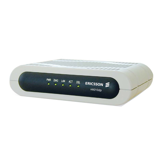
2.2.1 Front Panel and LED Indicators The front panel of the HM210dp/di contains five control lamps (LEDs) that indicate the status of the modem. A general description of each LED is provided in the table below (from left to right):... -
Page 12: Back Panel And Connectors
Choosing a Place for the Router The HM210dp/di should be placed on a flat surface. Be sure to choose a location that enables you to see the LEDs, is close to a power outlet, ADSL outlet, and the PC. -
Page 13: Connecting The Hardware
2. Connect to a PC or hub/switch: - to a single PC Attach one end of the provided Ethernet cable (straight-through) to the port labeled LAN on the HM210dp/di. Connect the other end to your PC’s Ethernet port. - to a hub/switch Attach one end of a “cross-over”... -
Page 14: Local Pc Configuration
DHCP Range The following instructions assume that your PC meets the following prerequisites: 1. Already is connected to the LAN port on the HM210dp/di through its network interface card (NIC). 2. Has the appropriate Ethernet adapter software installed. 3. Has the TCP/IP protocol installed. If not, refer to Microsoft documentation to install the TCP/IP protocol. -
Page 15: In Windows 2000
5. Some configuration files may be copied to your hard disk and if a “Settings Changes” message asks you to restart your PC, you should answer Yes. 3.1.2 In Windows 2000: 1. From the Start menu select Settings > Control Panel and double- click on the Network and Dial-up Connections icon. -
Page 16: Assigning Static Ip Addresses To Your Pcs
Local PC Configuration Assigning Static IP Addresses to your PCs In some cases, you may want to assign static IP information to your PCs directly if: In bridged mode, you have completed the initial configuration and you need to use the IP address and default gateway given by your ISP. -
Page 17: In Windows 2000
3.2.2 In Windows 2000: 1. From the Start menu select Settings > Control Panel and double- click on the Network and Dial-up Connections icon. 2. Double-click on the Local Area Connection icon for the HM310dp. Be sure to choose the correct one if you have several dial-up icons. 3. -
Page 18: Getting Started With The Configuration Manager
You can access the Configuration Manager from any computer connected to the HM210dp/di. Follow the instructions below: 1. At any PC connected to the HM210dp/di, open a web browser, type the following URL in the address (or location) box, and press <Enter>:... -
Page 19: Functional Layout
Functional Layout The Configuration Manager tasks are grouped into categories, which you can access by clicking the tabs at the top of each page. Each tab displays the available tasks in a horizontal menu at the top of the page. You can click on these menu items to display the specific configuration options. -
Page 20: Commonly Used Buttons And Icons
Getting Started with the Configuration Manager 4.2.1 Commonly Used Buttons and Icons The table below describes buttons and icons commonly used in the Configuration Manager. Button / Symbol Description Stores in temporary system memory any changes you have made on the current page. See section 4.4 “Committing Changes and Rebooting”... -
Page 21: En/Lzt 108 6492 R2 - October 2003
The Home Page and System View Table The Home page - System View – displays when you first access the Configuration Manager. This page is one of two options available in the Home tab (the other is the Quick Configuration page, as described in section 4.5). - Page 22 This typically includes an Ethernet interface named eth-0. Displays the status of various services that the HM210dp/di performs to help you manage your network. A green ball indicates the service is active and a red X indicates that it is inactive: NAT –...
-
Page 23: Commiting Changes And Rebooting
Commiting Changes and Rebooting Whenever you change system settings, the changes are initially placed in a temporary storage (called random access memory or RAM). Your changes are made effective when you submit them, but will be lost if the device is reset or turned off. -
Page 24: Rebooting The Hm210Dp/Di Using Options
Getting Started with the Configuration Manager 4.4.1 Rebooting the HM210dp/di using Options If, after rebooting the device, you find that it does not operate properly with the new configuration, you can reboot using options that reactivate a previous configuration or the factory default configuration. - Page 25 Reboot from Minimum Configuration NOTE! Do not reboot the device using the Reset button on the back panel of the HM210dp/di to activate new changes. This button resets the device settings to the manufacturer’s default values. Any custom settings will be lost.
-
Page 26: Quick Configuration
Quick Configuration The Quick Configuration page allows you to quickly configure your HM210dp/di for Internet connection. Your ISP should provide you with necessary information to complete the quick setup. To quickly configure the system, go to Home > Quick Configuration. The... - Page 27 If your ISP has assigned a public IP address to your LAN, enter the IP address and associated subnet mask in the boxes provided. Select Enable if you want the HM210dp/di to act as a DHCP server for your LAN. When enabled, the IP address specified above will be used as the default route for your LAN.
- Page 28 Getting Started with the Configuration Manager Field Primary/Secondary DNS Server: After completing the required settings, click the Submit button. Then, go to Admin > Commit & Reboot and click the Commit button to store your changes to permanent memory. Description You may just keep the default 0.0.0.0.
-
Page 29: Basic Configuration
Contact your ISP to determine whether you should change any existing values. Configuring the ATM Virtual Circuit As your LAN computers access the Internet via the HM210dp/di, data is exchanged with your ISP through a complex network of telephone switches, Internet routers, servers, and other specialized hardware. These various devices communicate using a common language, or protocol, called Asynchronous Transfer Mode (ATM). - Page 30 Basic Configuration Enter the provided fields as below: Field VC Interface: VPI and VCI: Mux Type: Max Proto per AAL5: 3. After entering the fields above, click the Submit button and when the confirmation page appears, click Close. 4. You will return to the ATM VC Configuration table and see the newly added ATM VC entry: Description Select a VC interface from the available...
-
Page 31: Modifying Atm Vcs
5. Select Admin > Commit & Reboot and click the Commit button to store your changes to permanent memory. 6. You may need to create a new WAN interface, or modify an existing interface, so that it uses the new VC. See the instructions in the following sections for configuring a PPP (section 5.2), EoA (section 5.3) or IpoA (section 5.4) interfaces, depending on the type you use to communicate with your ISP. -
Page 32: Configuring Ppp Interfaces
Basic Configuration Configuring PPP Interfaces When powered on, the HM210dp/di initiates a connection through your DSL line to your ISP. The Point-to-Point (PPP) protocol is commonly used between ISPs and their customers to identify and control various communication properties, including: Identifying the type of service the ISP provides to a given customer. - Page 33 2. Click the Add button to display the PPP Interface – Add page: 3. Enter the provided fields as below: Field PPP Interface: ATM VC: Interface Sec Type: EN/LZT 108 6492 R2 - October 2003 Description Select a PPP interface from the available interfaces, e.g.
- Page 34 When set to Enable, the DNS address learned through the PPP connection will be distributed to clients of the device’s DHCP server. This option is useful only when the HM210dp/di is configured to act as a DHCP server for your LAN. Indicates whether the HM210dp/di should use the IP address assigned to this connection as its default route.
-
Page 35: Checking Your Connection Status
Security Information Security Protocol: Login Name: Password: 5. After entering the fields above, click the Submit button and when the confirmation page appears, click Close. 6. You will return to the PPP Configuration page and see the newly added PPP interface. The “Oper. Status” column indicates if the link is currently up or down: 7. -
Page 36: Modifying And Deleteing Ppp Interfaces
Basic Configuration 5.2.3 Modifying and Deleteing PPP Interfaces To modify a PPP interface, display the PPP Configuration page and click in the “Action(s)” column for the interface you want to modify. The PPP Interface – Modify page displays. You can change only the status of the PPP connection, the security protocol, your login name and your password. -
Page 37: Configuring Eoa Interfaces
Configuring EoA Interfaces This section describes how to configure an Ethernet-over-ATM interface on the HM210dp/di, if one is needed to communicate with your ISP. The Ethernet-over-ATM (EoA) protocol is often referred to as RFC1483, which is the Internet specification that defines it. It is commonly used to carry data between local area networks that use the Ethernet protocol and wide-area networks that use the ATM protocol. - Page 38 Basic Configuration 2. Click the Add button to display the EOA Interface – Add page: 3. Enter the provided fields as below: Field EOA Interface: Interface Sec Type: Description Select an EoA interface from the available interfaces, e.g. eoa-0. Public / Private / DMZ. This setting defines the type of firewall protections that are in effect on the interface as described below:...
- Page 39 EoA interface will operate. 0.0.0.0 / 0.0.0.0 To use the HM210dp/di as a bridge, you don’t need to set the IP address and subnet mask. Just keep the default.
- Page 40 Basic Configuration 6. Select Admin > Commit & Reboot and click the Commit button to store your changes to permanent memory. EN/LZT 108 6492 R2 - October 2003...
-
Page 41: Configuring Ipoa Interfaces
Configuring IPoA Interfaces This section describes how to configure an IPoA (Internet Protocol-over- ATM) interface on the HM210dp/di. An IPoA interface can be used to exchange IP packets over the ATM network, without using an underlying Ethernet over ATM (EoA) connection. - Page 42 Enable / Disable Indicates whether the HM210dp/di uses the IP address assigned to this interface, if any, as its default route for your LAN. Your system can have only one default route.
-
Page 43: Checking Your Connection Status
4. After entering the fields above, click the Submit button and when the confirmation page appears, click Close. 5. You will return to the IpoA Configuration table and see the newly added IPoA entry: 6. Click Map in the “Action” column. The IPoA Interface – Map page appears: 7. -
Page 44: Bridging Connection Mode
Basic Configuration Bridging Connection Mode The HM210dp/di can be configured to act as a bridging device between your LAN and your ISP. Bridges are devices that enable two or more networks to communicate as if they are two segments of the same physical LAN. -
Page 45: Check Your Connection Status
5.5.2 Check Your Connection Status Select Home > System Mode. The WAN Interface item should display the interface you created to communicate with your ISP. A green ball in the Status field indicates a successful connection: 5.5.3 Deleting a Bridge Interface To make an interface non-bridgeable, display the Bridge Configuration page and click Click OK to confirm the deletion. -
Page 46: Configuring Ip Routes
Most users do not need to define IP routes. On a typical small home or office LAN, the existing routes that set up the default gateways for your LAN computers and for the HM210dp/di provide the most appropriate path for all your Internet traffic. You may need to define routes if: Your network setup includes two or more networks or subnets. -
Page 47: Viewing The Ip Routing Table
IP address of the first hop the data should take. This table is known as the device’s routing table. To view the HM210dp/di routing table, select Routing > IP Route. The following page appears: The IP Route Table displays a row for each existing route. These include... - Page 48 Configuring IP Routes Field Destination: Netmask: NextHop IFName: Route Type: Route Origin: Action: Description Specifies the IP address of the destination computer. The destination can be specified as the IP address of a specific computer or an entire network. It can also be specified as all zeros to indicate that this route should be used for all destinations for which no other route is defined (this is the route that creates the default...
-
Page 49: Adding Ip Routes
Adding IP Routes To add an IP route to the routing table, follow the steps below: 1. Select Routing > IP Route > Add. The IP Route – Add page appears: 2. Specify the destination, netmask, and gateway or next hop for this route. -
Page 50: Configuring Dhcp
When you enable DHCP on a network, you allow a device – such as the HM210dp/di or a router located with your ISP – to assign temporary IP addresses to your computers whenever they connect to your network. The assigning device is called a DHCP Server and the receiving device is a DHCP Client. -
Page 51: Configuring Dhcp Server
If you have another PC or device on your network that is already performing the DHCP server function, you can configure the LAN port on the HM210dp/di to be a DHCP client of that server. NOTE! Your can input settings for both DHCP server and DHCP relay mode, and then activate either mode at any time. -
Page 52: Creating Dhcp Server Address Pools
Configuring DHCP 7.3.1 Creating DHCP Server Address Pools To create a pool of IP addresses follow the steps below: 1. Select LAN > DHCP Server. The DHCP Server Configuration page appears: Depending on your preconfigured settings, the table may display one or more address pools, each in a row, or may be empty. - Page 53 Enter the provided fields as below: The Start IP Address, End IP Address, Net Mask and Gateway Address fields are required, the others are optional. Field Start IP Address: End IP Address: Mac Address: EN/LZT 108 6492 R2 - October 2003 Description Specify the lowest and highest IP addresses in the pool, up to a maximum range of 254...
-
Page 54: Enabling Dhcp Server Mode
Configuring DHCP Netmask: Domain Name: Gateway Address: DNS/SDNS Address: SMTP … SWINS Address: (optional) 3. Click the Submit button. A confirmation page appears briefly to indicate that the pool has been added successfully. After a few seconds, the DHCP Server Pool – Add page displays with the newly added pool. -
Page 55: Configuring Your Pcs As Dhcp Clients
2. A page appears to confirm the change. 3. Select Admin > Commit & Reboot and click the Commit button to save your changes to permanent storage. 7.3.3 Configuring Your PCs as DHCP Clients For each computer that you want to configure to receive IP information automatically, configure the TCP/IP properties to “Obtain an IP address automatically”... -
Page 56: Excluding Ip Addresses From A Pool
7.3.6 Viewing Current DHCP Address Assignments When the HM210dp/di functions as a DHCP server for your LAN, it keeps a record of any addresses currently leased to your computers. EN/LZT 108 6492 R2 - October 2003... -
Page 57: Configuring Dhcp Relay
In this case, you can configure the device as a DHCP relay agent. When a computer on your network requests Internet access, the HM210dp/di contacts your ISP to obtain an IP address (and other information), and then forwards that information to the computer. -
Page 58: Enabling Dhcp Relay Mode
This page provides a text box for entering the IP address of your ISP’s DHCP server and a table that lists the interfaces on your HM210dp/di that can relay DHCP information. 2. Type the IP address of your ISP’s DHCP server in the fields provided. -
Page 59: Configuring Your Pcs As Dhcp Clients
2. A page appears to confirm the change. 3. Select Admin > Commit & Reboot and click the Commit button to save your changes to permanent storage. 7.4.3 Configuring Your PCs as DHCP Clients For each computer that you want to configure to receive IP information automatically, configure the TCP/IP properties to “Obtain an IP address automatically”... -
Page 60: Configuring Nat
7 “Configuring DHCP”. On the HM210dp/di, you set up a NAT rule to specify that whenever one of your computers communicates with the Internet, (that is, it sends and receives IP data packets) its private IP address –... -
Page 61: Viewing Nat Configuration
They provide a measure of security for your LAN by enabling you to assign private IP addresses and then have these and the source port numbers swapped out before your computers access the Internet. The type of NAT function described above is called network address port translation (NAPT). - Page 62 Configuring NAT default), the NAT Rule Configuration page, and the NAT Translations page. Enable/Disable radio buttons, which allow you to turn on or off the NAT feature. The NAT Global Information table, which displays the following settings that apply to all NAT rule translations: Field TCP Idle Timeout(sec):...
-
Page 63: Viewing Nat Rules And Rule Statistics
The table provides basic information for each NAT rule you have set up. You can click the Clear button to restart the accumulation of the statistics at their initial values. Viewing NAT Rules and Rule Statistics To view the NAT Rules currently defined on your system, select Services > NAT and select NAT Rule Entry in the NAT Options drop-down list. - Page 64 Configuring NAT The NAT Rule Configuration table displays a row containing basic information for each rule. For a description of these fields, refer to the instructions for adding rules in section 0 “Adding NAT Rules”. From the NAT Rule Configuration page, you can click the Add button to add a new rule, or use the icons in the “Action”...
-
Page 65: Viewing Current Nat Translations
button to reset the statistics to zeros and the Refresh button to display newly accumulated data. Viewing Current NAT Translations To view a list of NAT translations that have recently been performed and which remain in effect (for any of the defined rules), select Services > NAT and select NAT Translations in the NAT Options drop-down list The NAT Translations page appears: For each current NAT translation session, the table contains the following... - Page 66 Configuring NAT NAT Direction Entry Age You can click NAT translation session. The NAT Translation – Details table is displayed. In addition to the information displayed in the NAT Translations table, this table displays the following for the selected current translation sessions: Field Translated InAddress: In Address:...
-
Page 67: Adding Nat Rules
4. From the “IF Name:” dropdown list, select the interface on the HM210dp/di to which this rule applies. Typically, NAT rules apply to communication between your LAN and the Internet. Because the device uses the WAN interface (named ppp-0 or eoa-0) to connect your LAN to your ISP, it is the usual IF Name selection. -
Page 68: The Rdr Rule
IP address for that computer. The computer’s private IP address is translated to your public IP address for all incoming and outgoing data packets. NOTE! Without an RDR rule (or BIMAP rule), the HM210dp/di blocks attempts by external computers to access your LAN computers. - Page 69 4. From the “IF Name:” dropdown list, select the interface on the HM210dp/di to which this rule applies. Typically, NAT rules apply to communication between your LAN and the Internet. Because the device uses the WAN interface (named ppp-0 or eoa-0) to connect your LAN to your ISP, it is the usual IF Name selection.
-
Page 70: The Basic Rule
Configuring NAT would typically be used for load balancing, whereby traffic is distributed among several redundant servers. 7. In the “Global Address From/To:” fields, type the public IP address assigned to you by your ISP. If you have multiple WAN interfaces, in both fields type the IP address of the interface to which this rule applies. - Page 71 4. From the “IF Name:” dropdown list, select the interface on the HM210dp/di to which this rule applies. Typically, NAT rules apply to communication between your LAN and the Internet. Because the device uses the WAN interface (named ppp-0 or eoa-0) to connect your LAN to your ISP, it is the usual IF Name selection.
-
Page 72: The Filter Rule
Configuring NAT 7. In the “Global Address From/To:” fields, type the starting and ending IP address that identify the pool of public IP addresses to be translated to your private IP addresses. Or, type the same IP address in both fields (if you also specified a single address in the previous step). - Page 73 4. From the “IF Name:” dropdown list, select the interface on the HM210dp/di to which this rule applies. Typically, NAT rules apply to communication between your LAN and the Internet. Because the device uses the WAN interface (named ppp-0 or eoa-0) to connect your LAN to your ISP, it is the usual IF Name selection.
-
Page 74: The Bimap Rule
Configuring NAT to a corresponding address in a range of global addresses (which you specify in the next step). 7. In the “Global Address From/To:” fields, type the starting and ending IP address that identify the pool of public IP addresses to be translated to your private IP addresses. - Page 75 4. From the “IF Name:” dropdown list, select the interface on the HM210dp/di to which this rule applies. Typically, NAT rules apply to communication between your LAN and the Internet. Because the device uses the WAN interface (named ppp-0 or eoa-0) to connect your LAN to your ISP, it is the usual IF Name selection.
-
Page 76: The Pass Rule
4. From the “IF Name:” dropdown list, select the interface on the HM210dp/di to which this rule applies. Typically, NAT rules apply to communication between your LAN and the Internet. Because the device uses the WAN interface (named ppp-0 or eoa-0) to connect your LAN to your ISP, it is the usual IF Name selection. - Page 77 5. In the “Local Address From/To:” fields, type the lowest and highest IP addresses that define the range of private addresses you want to be passed without translation. If you want the PASS rule to act on only one address, type that address in both fields.
-
Page 78: Configuring Dns Server Addresses
In either case, you can specify the actual addresses of the ISP’s DNS servers (on the PC or in the DHCP pool), or you can specify the address of the LAN port on the HM210dp/di (e.g. 192.168.1.1). When you specify the LAN port IP address, the device performs DNS Relay, as described in the following section. -
Page 79: Overview Of Dns Relay
Overview of DNS Relay When you specify the HM210dp/di’s LAN port IP address as the DNS address, then the device automatically performs “DNS relay”; i.e. because the device itself is not a DNS server, it forwards domain name lookup requests it receives from the LAN PCs to a DNS server at the ISP. It then relays the DNS server’s response to the PC. - Page 80 Configuring DNS Server Addresses If “Use DNS” is disabled, you must delete the interface and create a new one with the new setting. Option 2 – Configuring DNS on the HM210dp/di: EN/LZT 108 6492 R2 - October 2003...
- Page 81 You can configure the DNS server address to be relayed on the modem if one of the following circumstances applies: Go to Service > DNS to display the DNS Configuration page: Type the IP address of the DNS server in an empty row and click Add.
-
Page 82: Configuring Rip
Most small home or office networks do not need to use RIP; they have only one router, such as the HM210dp/di, and one path to an ISP. In these cases there is no need to share routes, because all Internet data from the network is sent to the same ISP gateway. -
Page 83: Configuring The Rip
10.2 Configuring the RIP Follow the steps below to configure your HM210dp/di to use RIP: 1. Select Services > RIP and the RIP Configuration page appears: 2. The page contains radio buttons for enabling or disabling the RIP feature and a table listing interfaces on which the protocol is currently running. -
Page 84: Viewing Rip Statistics
The Receive Mode setting indicates the RIP version(s) in which information must be passed to the HM210dp/di in order to be accepted into its routing table. RIP version 1 is the original RIP protocol. Select RIP1 if you have devices that communicate with this interface that understand RIP version 1 only. -
Page 85: En/Lzt 108 6492 R2 - October 2003
Configuring RIP You can click the Clear button to reset all statistics to zero and the Refresh button to display any newly accumulated data. EN/LZT 108 6492 R2 - October 2003... -
Page 86: Configuring Firewall Settings
Configuring Firewall Settings Configuring Firewall Settings The Configuration Manager provides built-in firewall functions, enabling you to protect the system against denial of service (DoS) attacks and other types of malicious accesses to your LAN. You can also specify how to monitor attempted attacks, and who should be automatically notified. - Page 87 Field Blacklist Status: Blacklist Period(min): Attack Protection: DOS Protection: Max Half open TCP Conn.: Max ICMP Conn.: EN/LZT 108 6492 R2 - October 2003 Configuring Firewall Settings Description If you want the device to maintain and use a black list, click Enable. Click Disable if you do not want to maintain a list.
-
Page 88: Configuring Ip Filters
When you define an IP filter rule and enable the feature, you instruct the HM210dp/di to examine each data packet it receives to determine whether it meets criteria set forth in the rule. The criteria can include the size of the... -
Page 89: Viewing Your Ip Filter Configuration
11.2.1 Viewing Your IP Filter Configuration To view your IP filter configuration, select Services > IP Filter. The IP Filter Configuration page appears: The IP Filter Configuration page displays global settings that you can modify, and the IP filter rule table, which shows all currently established rules. -
Page 90: Configuring Ip Filter Global Settings
Private – Typically, the global setting for private interfaces is Accept, so that LAN computers have access to the Internet connection of the HM210dp/di. Public – The interface connect to the Internet, e.g. PPP, EoA and IpoA interfaces. Typically, the global setting for public interfaces is... - Page 91 Configuring Firewall Settings 2. Enter or select data for each field that applies to your rule: EN/LZT 108 6492 R2 - October 2003...
- Page 92 Configuring Firewall Settings Field Rule ID: Action: Direction: Interface: In Interface: Log Option: Security Level: Blacklist Status: Log Tag: Description Rules are processed from lowest to highest on each data packet, until a match is found. It is recommended that you assign rule Ids in multiples of 5 or 10 (e.g.
- Page 93 Start/End Time: Src IP Address: Dest IP Address: Protocol: Apply Stateful Inspection: EN/LZT 108 6492 R2 - October 2003 Configuring Firewall Settings Enable if you configure a Log Tag. The time range during which this rule is to be in effect, specified in military units.
- Page 94 Configuring Firewall Settings Source Port: Dest Port: TCP Flag: ICMP Type: ICMP Code: IP Frag Pkt: Port number criteria for the computer(s) from which the packet originates. This field will be dimmed (unavailable for entry) if you have not specified a protocol critera. See the description of Src IP Address for the selection options.
- Page 95 IP Option Pkt: Packet Size: TOD Rule Status: 3. When you are done selecting criteria, ensure that the Enable radio button is selected and then click the Submit button. If the security level of the rule matches the globally configured setting, a green ball in the “Status”...
-
Page 96: Viewing Ip Filter Statistics
Configuring Firewall Settings 11.2.3.1 IP Filter Rule Examples Example 1 – Blocking a specific computer on your LAN from accessing web servers on the Internet; 1. Add a new rule for outgoing packets on the ppp-0 interface from any incoming interface (this would include the eth-0 interface, for example). -
Page 97: Managing Current Ip Filter Sessions
Managing Current IP Filter Sessions When two computers communicate using the IP protocol, an IP session is created for the duration of the communication. The HM210dp/di allows a fixed number of concurrent IP sessions. You can view information about each current IP session and delete sessions (for security reasons, for example). -
Page 98: Blocking Specific Protocols
You can click the Refresh button to display newly accumulated data. 11.3 Blocking Specific Protocols The Blocked Protocols feature enables you to prevent the HM210dp/di from passing any data that uses a particular protocol. Unlike the IP Filter feature, you cannot specify additional criteria for blocked protocols, such as particular users or destinations. - Page 99 Check the protocol type you want to block and click the Submit button. Make sure to use the Commit feature to save your changes to the permanent memory. To unblock a specific protocol, uncheck the protocol and repeat the submit and commit tasks.
- Page 100 Configuring Firewall Settings AppleTalk NetBEUI BPDU IPV6 Multicast 802.1.Q hardware address (i.e. MAC addresses). Certain types of computers, such as diskless workstations, must use RARP to determine their IP address before communicating with other network devices. A networking protocol used for Apple Macintosh networks.
-
Page 101: Administration Tasks
12.1 Changing the System Date and Time The HM210dp/di keeps a record of the current date and time, which it uses to calculate and report various performance data. You can change the date and time as required. On this page you may also specify the host name and the domain name in the fields provided. -
Page 102: Configuring User Names And Passwords
LAN port on the HM210dp/di. You can use this field to specify and Internet domain name for the HM210dp/di. The next time you access the Configuration Manager, you can type the domain name and the device name (see the Name field above) in your Web browser. - Page 103 To add login User Id or change the login password, proceed as follows: 1. Select Admin > User Config. The User Configuration page appears: 2. To modify the login password click the “Action(s)” column and then change the current password: 3.
-
Page 104: Upgrading The Software
The Configuration Manager provides an easy way to upload a new software image, or a specific part of the image, to the memory on the HM210dp/di. To perform the upgrade task, download the required image file to your local host PC and follow the steps below: 1. -
Page 105: Using Diagnostics
4. Power off the unit, wait a few seconds, and then turn it on again to activate the new software. NOTE! DO NOT interrupt the upgrade process. Otherwise it might cause damage to your modem. 12.4 Using Diagnostics The diagnostics feature executes a series of test of your system software and hardware connections. - Page 106 Administration Tasks Select the VC on which you want to execute diagnostics and then click the Submit button. The diagnostics utility will run a series of test to check whether the device’s connections are up and working. This takes only a few seconds and the results for each test are displayed on screen.
-
Page 107: Modifying Port Settings
80, 23 and 21 respectively. It is possible that you want to designate a publicly accessible HTTP, Telnet or FTP server on your LAN side and you want to shift the modem’s HTTP/Telnet/FTP service to use a non-standard port number. If this is the case, select Admin > Port Settings to view the Port Settings page: Modify the port settings and click the Submit button. -
Page 108: Viewing System Alarms
Administration Tasks 12.6 Viewing System Alarms You can use the Configuration Manager to view information about alarms that occur in the system. Alarms, also called traps, are caused by a variety of system events, including connection attempts, resets, and configuration changes. -
Page 109: Viewing Dsl Line Information
Viewing DSL Line Information To view configuration parameters and performance statistics for the ADSL line, select WAN > DSL. The DSL Status page displays: The DSL Status page displays the current information on the DSL line performance. The page refreshes about every 10 seconds. In the DSL Status table, the Operational Status: setting displays a red, orange, or green ball to indicate that the DSL line is idle, starting up, or up- and-running, respectively. - Page 110 Viewing DSL Line Information You can click the Clear button to reset all counters to zero, and the Refresh button to redisplay the page with newly accumulated values. You can click the DSL Param button to display data about the configuration of the DSL line, as shown below: The DSL Parameters and Status table displays settings preconfigured by the product manufacturer or your ISP.
- Page 111 Viewing DSL Line Information The DSL Statistics page reports error data relating to the last 15 minutes interval, the current day, and the previous day. At the bottom of the page, the Detailed Interval Statistic table displays links you can click to display detailed data for each 15 minute interval in the past 24 hours.
-
Page 112: Troubleshooting
Troubleshooting Troubleshooting This chapter suggests solutions for resolving some of the problems you might encounter when using your HM210dp/di, and provides instructions for using several IP utilities to diagnose problems. 14.1 LEDs Indication/Symptom The PWR LED does not illuminate after the product is turned on. -
Page 113: Internet Access
PCs is correct for your ISP. If you specified that the DNS server be assigned dynamically from a server, then verify with your ISP that the address configured on the HM210dp/di is correct. Then, you can use the PING utility to test connectivity with your ISP’s DNS server. -
Page 114: Configuration Manager Program
Use the PING utility to check whether your PC can communicate with the HM210dp/di’s LAN IP address (by default 192.168.1.1). If it cannot, check the Ethernet cabling. Verify that you are using Internet Explorer v5.0 or later, or Netscape Navigator v6.1 or later. -
Page 115: How To Use Ipconfig
4. Make sure that the Default gateway is the IP address of your HM210dp/di. If it is not, you will not be able to connect to the Internet. If you are using DHCP, click the Release and then the Renew buttons to receive the correct IP settings. -
Page 116: How To Use Ping
Troubleshooting 14.4.3 How to use PING PING is a command you can use to check whether your PC can recognize other computers on your network and the Internet. A ping command sends a message to the computer you specify. If the computer receives the message, it sends messages in reply. -
Page 117: Important Information
Read this information before using your Ericsson ADSL Modem HM210dp/di. Your ADSL Modem HM210dp/di is a highly sophisticated electronic device. To get the most out of your product, be sure to read the following text about product care, safety and efficient use. -
Page 118: License Agreement
Important Information 15.2 License Agreement This is a legal agreement, Agreement, between you, Licensee, the recipient of the enclosed Software on compact disc, diskette or any other media and any upgrades thereof, and Ericsson AB, the Vendor. By opening the sealed software package and/or using the software you are agreeing to be bound by the terms of this Agreement. -
Page 119: Intended Use
and your exclusive remedy under this warranty (which is subject to you returning the Software to an certified reseller with a copy of your receipt) will be, at Vendor's option, to replace the disc(s)/ diskette(s) or refund the purchase price for the Software and terminate this Agreement. Except for the above express limited warranties, Vendor and its suppliers make and you receive no warranties or conditions either express, implied, statutory or otherwise and Vendor and its suppliers specifically disclaim any... -
Page 120: Regulatory Information
Important Information 15.3 Regulatory Information 15.3.1 EU Directives The HM210dp/di meet the following EU directives for the CE-mark: 73/23/EEC, Low Voltage Directive (LVD) 89/336/EEC, Electromagnetic Compatibility Directive (EMC) 1999/5/EC, Radio Equipment and Telecommunication Terminal Directive (R&TTE). 15.3.1.1 Declaration of Conformity 15.3.2... -
Page 121: Emc Approvals
CAUTION! Always disconnect all telephone lines from the wall outlet before servicing or disassembling this equipment. 15.3.3 EMC Approvals The HM210dp/di is approved according to the following EMC standards: EN 300386:2000 EN 55022:1998 Class B EN 55024:1998 EN 61000-3-2:2000 EN 61000-3-3:1995 FCC Part 15, Class B, ANSI C63.4-1992... - Page 122 Increase the separation between the ADSL Modem HM210dp/di and the affected equipment. Connect the ADSL Modem HM210dp/di power supply to an outlet on a circuit different from that to which the affected equipment is connected. Consult your service provider or an experienced radio/TV technician for help.
-
Page 123: Telecom Approval
15.3.4 Telecom Approval The HM210dp/di is approved according to the following telecom standard: FCC Part 68 15.3.4.1 FCC Part 68 Statement The Federal Communications Commission (FCC) has established Rules which permit this device to be directly connected to the telephone network. -
Page 124: Caution
OEM type: AA-1860. Input: 120 VAC, 60Hz. Output: 16VAC, 600mA. NOTE! The ADSL Modem HM210dp/di is for use only with one of the above approved power supply adapter. In the event of equipment malfunction, replace only with an AC/DC Adapter specified by Ericsson. -
Page 125: Intended Use
15.3.8 Intended Use The HM210dp/di is intended for indoor public and private use. EN/LZT 108 6492 R2 - October 2003 Important Information... -
Page 126: Glossary
Bridging contrasts with routing, which can add more intelligence to data transfers by using network addresses instead. The HM210dp/di can perform both routing and bridging. Typically, when both functions are enabled, the device routes IP data and bridges all other types of data. - Page 127 Broadband A telecommunications technology that can send different types of data over the same medium. DSL is a broadband technology. Broadcast To simultaneously send the same message to multiple recipients. CHAP Short for Challenge Handshake Authentication Protocol. A type of authentication in which the authentication agent (typically a network server) sends the client program a random value that is used only once and an ID value.
- Page 128 Glossary The DNS system is, in fact, its own network. If one DNS server doesn't know how to translate a particular domain name, it asks another one, and so on, until the correct IP address is returned. Domain name A domain name is a user-friendly name used in place of its associated IP address Downstream The direction of a downstream signal is from the ISP/service provider to the...
- Page 129 Glossary network. Firewalls can be implemented in both hardware and software, or a combination of both. Firewalls are frequently used to prevent unauthorized Internet users from accessing private networks connected to the Internet, especially intranets. All messages entering or leaving the intranet pass through the firewall, which examines each message and blocks those that do not meet the specified security critera.
- Page 130 Glossary Alternatively, the maximum number of hops that a packet is allowed to take before being discarded (see also TTL). Host A computer that is connected to a TCP/IP network, including the Internet. Each host has a unique IP address. HTTP Short for HyperText Transfer Protocol.
- Page 131 Private IP addresses are also LAN IP addresses, but are considered "illegal" IP addresses to the Internet. They are private to an enterprise while still permitting full network layer connectivity between all hosts inside an enterprise as well as all public hosts of different enterprises. Short for Internet Service Provider, a company that provides access to the Internet.
- Page 132 Ethernet to the Internet through a common broadband medium, such as a single DSL line, wireless device or cable modem. All the users over the Ethernet share a common connection, so the Ethernet principles supporting multiple users in a LAN combine with the principles of PPP, which apply to serial connections.
- Page 133 the circuit is preprogrammed by the carrier as a path through the network. It does not need to be set up or disconnected for each session. Remote In a physically separate location. For example, an employee away on travel who logs in to the company’s intranet is a remote user. Short for Request For Comments, a series of notes about the Internet, started in 1969 (when the Internet was the ARPANET).
- Page 134 Glossary T1.413 The American National Standards Institute (ANSI) standard for asymmetric digital subscriber line using discrete multitone modulation, which the G.dmt standard is based on. Abbreviation of Transmission Control Protocol, and pronounced as separate letters. TCP is one of the main protocols in TCP/IP networks. Whereas the IP protocol deals only with packets, TCP enables two hosts to establish a connection and exchange streams of data.
- Page 135 Glossary Upstream The direction of an upstream signal is from the user's computer to the ISP/service provider (uploading). - V - A VC (Virtual Circuit) is a connection from your ADSL router to your ISP. VPI and VCI A VPI (Virtual Path Identifier) is an 8-bit field while VCI (Virtual Channel Identifier) is a 16-bit field in the ATM cell header.
Need help?
Do you have a question about the HM210DP/DI and is the answer not in the manual?
Questions and answers