
Related Manuals for JUKI TL-98Q


Summary of Contents for JUKI TL-98Q
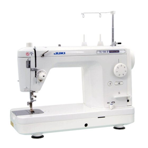
- Page 1 1-NEEDLE LOCKSTITCH SEWING MACHINE WITH AUTOMATIC THREAD TRIMMER FOR PROFESSIONAL TL-98Q/98QE SERVICE MANUAL...
-
Page 2: Table Of Contents
CONTENTS [1] SPECIFICATIONS OF TL-98Q/98QE ............. 1 [2] NAMES OF COMPONENTS ................3 [3] DISASSEMBLY AND ASSEMBLY ..............3 [4] PRINTED CIRCUIT BOARD DIAGRAM (CONNECTOR LAYOUT) ..... 17 [5] ADJUSTMENTS OF COMPONENTS ............18 WARNING : To avoid the risk of fire, electric shock, injury to persons or damage to components, especially keep the following : •... -
Page 3: Specifications Of Tl-98Q/98Qe
: Commercially-available presser foot for industrial sewing machine (SL2) can be used. (Setscrew type) 9. Lift of presser foot : By lever : 7 mm Max. by lever : 10 mm (TL-98Q) / 12 mm (TL-98QE) By knee lifter : 12 mm 10. Thread tension : Disk pressure adjusting type with simplified disk pressure scale 11. - Page 4 ON state when temperature has fallen. (8) Dimensions and weight Main unit : 452W x 219L x 350H (mm) Weight : 11.5kg (TL-98Q) 10.5kg (TL-98QE) (9) Power consumption Whole sewing machine : 120V 1.4A 60Hz...
-
Page 5: Names Of Components
14. Hand lifter lever ........13 5. MAIN circuit board asm......5 15. Drop-feed knob ........14 Function components TL-98Q 1. Motor asm. and transformer asm... 5 Automatic thread trimming components 2. Handwheel and clutch ......6 1. Looper mas. asm........15 3. - Page 6 6 Convex of presser Outer Components spring regulator knob 5 Slit of presser regulating screw 1 Arm cover setscrew 1. Arm cover asm. SM5042005SN 2 Bobbin 4 MAIN circuit winder 3 Arm cover board case cover connector Assembly Point Disassembly ™...
- Page 7 4. Bed cover mas. asm. 1 Bed cover setscrew 1 Bed cover setscrew SM5051255SN Disassembly Assembly Point ™ Remove six 1 setscrews and ™ Attach bed cover and tighten remove bed cover. setscrews. 5. MAIN circuit board asm. 2 MAIN circuit board case setscrew A Preparation 3 MAIN circuit board setscrew SL5030831SF...
- Page 8 2. Handwheel and clutch !0 Groove of handwheel Preparation ™ Remove belt cover. 7 Convex of handwheel bushing ™ Remove arm cover. 9 Motor pulley 1 Handwheel setscrew 6 Groove of 2 Handwheel handwheel bushing 5 Hook portion of clutch spring 4 Angle portion of clutch spring When removing motor pulley, remove cord guide...
- Page 9 4. Presser bar 2 Presser spring regulator Preparation Threader support plate setscrew (upper) ™ Remove arm cover asm. 4 Presser spring SL5040631SE ™ Remove face plate mas. asm. 7 Indicating needle of ™ Remove presser foot and setscrew. presser spring regulator Threader support plate mas.
- Page 10 6. Thread take-up 1 Thread take-up supporting shaft setscrew SM8050602TP 6 Thread take-up Preparation support 3 Thread take-up ™ Remove arm cover asm. supporting shaft ™ Remove face plate mas. asm. 4 Needle bar crank ™ Remove presser bar. ™ Remove needle bar. 5 Thread take-up 2 Needle bar crank setscrew...
- Page 11 ™ There should not be no torsion and tighten with 1 setscrews. thread trimming switch case. between switch and frame. ™ Remove thread trimming switch case. 11.Wire holder (TL-98Q) 2 Wire tube presser setscrew Preparation SM4040655SN ™ Remove outer components. 1 Nut of setscrew...
- Page 12 When removing the wire from frame, make sure of wire route in frame. 12.Knee lifter lever 1 Knee lifter lever shaft spring setscrew TL-98Q SM5030455SF Preparation ™ Remove outer components. (Excluding belt cover and motor cover) ™ Raise presser foot.
- Page 13 TL-98QE Preparation ™ Remove outer components. (Excluding belt cover and motor cover) ™ Raise presser foot. !0 Knee lifter lever shaft 6 Knee lifter lever 4 Knee lifter link snap pin 1 Knee lifter lever shaft spring setscrew 3 Claw lever actuating plate SM5030455SF 5 Knee lifter lever shaft stop setscrew SM8040602TP...
- Page 14 13. Hook driving shaft pulley Preparation ™ Remove outer components. (Excluding stop solenoid) ™ Loosen idler. ™ Remove needle. 5 Hook driving shaft pulley eccentric shaft 3 Hook driving shaft pulley E-ring (E-6) 9 Thread trimmer cam screw No. 1 1 Timing belt 6 Hook driving shaft pulley eccentric shaft bushing...
- Page 15 14. Hand lifter lever 1 Hand lifter lever TL-98Q 2 Hand lifter lever shaft 3 M4 screw Disassembly Assembly Point ™ Enter 2 hand lifter lever shaft into ™ Enter 3 to 4 screw threads of M4 ™ End face of lever shaft that is fit screw (arm cover setscrew) in the the hole on frame.
- Page 16 15. Drop-feed knob 1 Drop-feed knob 3 E-ring 5 Wire installing plate asm. 2 DF adjusting arm spring 6 DF adjusting arm asm. 4 Drop feed knob shaft setscrew Disassembly Assembly Point ™ Set 1 drop-feed knob to "NOT ™ Pass 1 drop feed knob through ™...
- Page 17 TL-98Q 5 Looper mas. asm. Automatic Thread Trimming Components setscrew 3 Looper link asm. SM5040855SN 1. Looper mas. asm. Preparation ™ Remove bed cover. 2 Looper link holding shaft 4 M o v i n g k n i f e...
- Page 18 3. Moving knife base mas. asm. Preparation ™ Remove bed cover. 3 Feed dog ™ Remove throat plate asm. 2 M o v i n g k n i f e base mas. asm. setscrew 1 Moving knife link SM4040855SP shaft A E-ring Disassembly Assembly...
-
Page 19: Printed Circuit Board Diagram (Connector Layout)
[4] PRINTED CIRCUIT BOARD DIAGRAM (CONNECTOR LAYOUT) AC120V (TL-98Q) Plug socket Thread trimmer Lamp solenoid Lamp SW (TL-98Q) Power SW Controller Controller socket CN23 Thread trimmer socket Thread trimmer FILTER MAIN circuit board CN11 CN22 (TL-98Q) circuit board SW circuit board... -
Page 20: Adjustments Of Components
12. Position of bobbin winder clutch ...... 22 (adjustment of thread tension disk open/close) 13. Adjustment of bobbin winder ......23 ................. 29 14. Position of threader support plate mas. asm. (TL-98Q) ............24 15. Vertical position of threader hook (TL-98Q) ..24 – –... -
Page 21: Height Of Needle Bar
™ Attach length gauge (needle) of #14 needle to needle bar, and adjust dimension from tip of needle to installing plane of throat plate on frame to 17.8 ± 0.1 mm (TL-98Q) / 18.1 ± 0.1 mm (TL-98QE). ™ Perform adjustment with needle bar connection setscrew. -
Page 22: Height Of Feed Dog
™ At this time, clearance provided between needle top and top surface of throat plate is 0 ± 0.2 mm. ™ Perform adjustment with feed cam setscrew. Feed cam setscrew Needle : TL-98Q (HA x 1 #14) TL-98QE (HL x 5 #14) Top surface of throat plate 0±0.2 mm... -
Page 23: Position Of Bobbin Case Positioning Finger
8. Position of bobbin case positioning finger ™ Loosen bobbin case positioning finger 1 setscrew. Needle ™ Make right-hand edge of convex portion of bobbin Top view case positioning finger spring align with 2 right- 0.3 to 0.5 mm hand edge of needle. ™... -
Page 24: Adjustment Of Bobbin Thread Tension
11. Adjustment of bobbin thread tension How to adjust Bobbin case Adjust with adjusting screw so that bobbin thread Adjusting screw tension when spun thread #60 is used becomes 0.176±0.02N. Bobbin thread 12. Position of bobbin winder clutch ™ Remove belt cover. How to adjust 1. -
Page 25: Adjustment Of Bobbin Winder
13. Adjustment of bobbin winder [Position of disengaging bobbin winder] How to adjust 1. Set 1 bobbin presser to the position where it is 16 mm away from 2 bobbin winding shaft. 2. Tighten 4 bobbin winder controller asm. with setscrew when concave portion of 3 bobbin winding shaft base adjusting plate is engaged with convex portion of 4 bobbin winder controller asm.. -
Page 26: Vertical Position Of Threader Hook (Tl-98Q)
14. Position of threader support plate mas. asm. (TL-98Q) How to adjust ™ Open face cover and remove arm cover asm. 1. Temporarily tighten 1 threader support plate mas. asm. with setscrews. 2. Adjust 1 threader support plate mas. asm. so that 2 Threader support plate position of threader shaft is 10.5 mm, making needle... -
Page 27: Automatic Thread Trimmer Mechanism
TL-98Q Automatic Thread Trimmer Mechanism 1. Positioning of moving knife arm installing plate (Adjustment of position of moving knife) ™ Loosen 1 nut of setscrew 2 Moving knife arm ™ Loosen 2 setscrews in installing plate and move installing plate setscrew... - Page 28 3. Thread trimmer cam timing (Needle-to-cam position) ™ Loosen setscrews in 1 thread trimmer auxiliary 4 Thread trimmer auxiliary link cam, 2 thread trimmer cam and 3 roller holding 1 Thread trimmer auxiliary cam cam. ™ Lower needle bar by 37˚ (1.95 mm) from its upper dead point.
- Page 29 3-6 Adjustment of thread trimmer clutch plate collar ™ After assembling 1 thread trimmer solenoid link A, perform adjustment of eccentricity with 2 thread trimmer clutch plate collar (adjustment of clearance between roller holding cam and link arm support plate) and adjust clearance to 1 to 3 mm.
- Page 30 ™ Insert a clearance gauge of 0.5 mm to contact part of 1 moving knife roller arm asm. and 2 looper link arm asm. and press 2 looper link arm asm. to 1 moving knife roller arm asm. 5 Nut 2 Looper link arm 0.5 spacer 4 Link arm support...
-
Page 31: Position And Protruding Amount Of Looper
4. Position and protruding amount of looper (Left/right position and moving amount) 4-1. Adjustment of left/right position of looper ™ Adjust with looper mas. asm. 2 so that center of inner hook is aligned with center of lopper 1. 2 Looper mas. asm. 1 Looper and inner hook 3 Looper (Convex that looper cam... - Page 32 HOUSEHOLD SEWING MACHINE DIVISION 8-2-1. KOKURYO-CHO, CHOFU-SHI, TOKYO 182-8655, JAPAN PHONE : (81)3-3480-5054 FAX : (81)3-3480-5037 Copyright C 2006 JUKI CORPORATION. All rights reserved throughout the world. 06.06 Printed in Japan (E) A9902-Q9E-000...
Need help?
Do you have a question about the TL-98Q and is the answer not in the manual?
Questions and answers