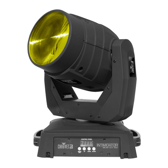
Chauvet Intimidator Beam LED 350 User Manual
Hide thumbs
Also See for Intimidator Beam LED 350:
- Quick reference manual (73 pages) ,
- User manual (61 pages) ,
- Features & specification (1 page)
Table of Contents
Advertisement
Quick Links
Advertisement
Table of Contents

Related Manuals for Chauvet Intimidator Beam LED 350


Summary of Contents for Chauvet Intimidator Beam LED 350
- Page 1 User Manual...
-
Page 2: Table Of Contents
ABLE OF ONTENTS 1. Before You Begin ......................3 What Is Included ......................... 3 Unpacking Instructions ........................ 3 Claims ..............................3 Text Conventions ........................3 Symbols ............................3 Disclaimer ........................... 3 Product at a Glance ........................4 Safety Notes ..........................4 2. -
Page 3: Before You Begin
Failure to report damage to the carrier immediately may invalidate your claim. In addition, keep the box and contents for inspection. For other issues, such as missing components or parts, damage not related to shipping, or concealed damage, file a claim with CHAUVET® within 7 days of delivery. Text Convention Meaning 1—512... -
Page 4: Product At A Glance
Product at a Use on Dimmer Auto Programs Glance Outdoor Use Auto-ranging Power Supply Sound Activated Replaceable Fuse User-Serviceable Master/Slave Duty Cycle Safety Notes These notes include important information about the mounting, usage, and maintenance of this product; read before using the product. ·... -
Page 5: Introduction
2. I NTRODUCTION Overview Power In Fuse Holder DMX In/Out Power Out Safety Loop LED Display Intimidator™ Beam LED 350 User Manual Rev. 2 Page 5 of 19... -
Page 6: Dimensions
Dimensions Page 6 of 19 Intimidator™ Beam LED 350 User Manual Rev. 2... -
Page 7: Setup
3. S ETUP AC Power The Intimidator™ Beam LED 350 has an auto-ranging power supply and it can work with an input voltage range of 100~240 VAC, 50/60 Hz. To determine the product’s power requirements (circuit breaker, power outlet, and wiring), use the current value listed on the label affixed to the product’s back panel, or refer to the product’s specifications chart. -
Page 8: Power Linking
The power linking diagram shown above corresponds to the North American version of the product ONLY! If using the product in other markets, you must consult with the local CHAUVET® distributor as power linking connectors and requirements may differ in your country or region. -
Page 9: Mounting
Mounting Before mounting the product, read and follow the safety recommendations indicated in the Safety Notes. Orientation The Intimidator™ Beam LED 350 may be mounted in any position; however, make sure adequate ventilation is provided around the product. · Rigging Before deciding on a location, always make sure there is easy access to the product for maintenance and programming. -
Page 10: Operation
4. O PERATION Control Panel To access the control panel functions, use the four buttons located underneath the display. Operation Button Function <MODE/ESC> Selects an operation mode or backs out of the current menu option <UP> Scrolls up the list of options or selects a higher value <DOWN>... -
Page 11: Starting Address
Starting Address When selecting a starting DMX address, always consider the number of DMX channels the selected DMX mode uses. If you choose a starting address that is too high, you could restrict the access to some of the product’s channels. The Intimidator™... -
Page 12: 14-Ch
8-CH (cont.) Channel Function Value Setting 000 ó 255 No function No Function 000 ó 007 Open 008 ó 012 Prism on 013 ó 130 Prism rotation with increasing speed Prism/Frost 131 ó 247 Reverse prism rotation with increasing speed 248 ó... - Page 13 14-CH Channel Function Value Setting (cont.) 000 ó 047 Gobos 1-6 048 ó 063 Animation effect (static) Gobo Wheel 064 ó 079 Animation speed (slow to fast) 080 ó 087 Gobo 5 shake, from slow to fast 088 ó 095 Gobo 4 shake, from slow to fast 096 ó...
- Page 14 14-CH Channel Function Value Percent/Setting (cont.) 000 ó 003 Closed 004 ó 007 Open 008 ó 076 Strobe effect with increasing speed Shutter 077 ó 145 Pulse strobe 146 ó 215 Random shutter 216 ó 255 Open 000 ó 007 No function 008 ó...
-
Page 15: Configuration (Standalone)
Configuration Set the product in one of the standalone modes to control without a DMX controller. Connect the product to a suitable power outlet. (Standalone) Turn the product on. Never connect a product that is operating in any standalone mode (either Automatic, or Sound-Active) to a DMX string connected to a DMX controller. -
Page 16: Display
Display To flip the LED display for better readability in any mounting situation, do the following: Press <MODE/ESC> repeatedly until diS or rdiS shows on the display. Press <UP> or <DOWN> to select diS (normal display mode) or rdiS (inverse display mode). -
Page 17: Technical Information
5. T ECHNICAL NFORMATION Product Dust build-up reduces light output performance and can cause overheating. This can lead to reduction of the light source’s life and mechanical wear. To maintain optimum Maintenance performance and minimize wear, clean the product at least twice a month. However, usage and environmental conditions contribute to increased cleaning frequency. -
Page 18: Technical Specifications
6. T ECHNICAL PECIFICATIONS Dimensions and Length Width Height Weight Weight 18.5 in (470 mm) Note: Max. height is 11.3 in (287 mm) 13.4 in (340 mm) 22 lb (9.8 kg) with moving head pointing up Note: Dimensions in inches rounded to the nearest decimal digit. Power Power Supply Type Range... -
Page 19: Returns
You must send the merchandise prepaid, in its original box, and with its original packing and accessories. CHAUVET® will not issue call tags. Clearly label the package with the RMA number. CHAUVET® will refuse any product returned without an RMA number.
Need help?
Do you have a question about the Intimidator Beam LED 350 and is the answer not in the manual?
Questions and answers