
Related Manuals for Chauvet TFX-24CON


Summary of Contents for Chauvet TFX-24CON
- Page 1 T E C H N I C A L R E F E R E N C E & M A N U A L Stage Designer™ 24 TFX-24CON CHAUVET 3000 North 29 Hollywood, FL 33020 U.S.A. Tel: 954-929-1115 Fax: 954-929-5560...
-
Page 2: Table Of Contents
Master Slider ... 20 Single Mode ... 20 Mix Mode ... 20 Dimmer Display ... 20 Blind and Home... 21 Park... 21 Issue Date: January 2004 Rev. No. Version 2.02 Date Description March 2004 TFX-24C Users Guide version 2.02: Revised: V.M. at CHAUVET... - Page 3 Double Preset ... 21 APPENDIX ...22 Maintenance... 22 DMX Primer ... 22 Returns Procedure... 22 Claims ... 22 General Troubleshooting ... 23 Issue Date: January 2004 Rev. No. Version 2.02 Date Description March 2004 TFX-24C Users Guide version 2.02: Revised: V.M. at CHAUVET...
-
Page 4: Warranty Information
If this product is not covered under the terms of this warranty, CHAUVET will advise you of the costs to carry out any repairs necessary and the unit will be shipped to you on receipt of payment for the work including the return freight charges. -
Page 5: Before You Begin
7. Always disconnect from power source before servicing or replacing fuse and be sure to replace with same fuse type. 8. To prevent risk of fire or shock, do not expose fixture to rain or moisture. What is enclosed Manual / Warranty Card TFX-24CON Controller A/C power adapter TFX-24C Users Manual Version 2.02... -
Page 6: Introduction
I N T R O D U C T I O N Introduction Technical Specifications Power Input DC 12~18V 500mA Minimum Adaptor AC ~230V 50Hz, DC 12V 500mA AC ~120V 60Hz, DC 12V 500mA DMX Out 3 pin male XLR MIDI In/Out/Thru –... -
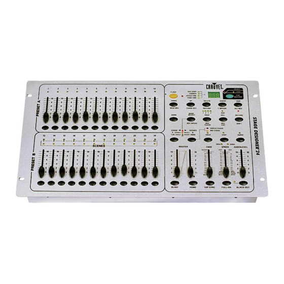
Page 7: Product Overview
I N T R O D U C T I O N Product Overview Front View 1. Preset A LEDs Indicates the current intensity of the channel enumerated. Channels 1 ~ 12. 2. Channel Sliders (1 ~ 12) These 12 sliders are used to control and/or program the intensities of channel 1 through 12. 3. - Page 8 I N T R O D U C T I O N 12. FADE Time Slider Used to adjust the fade time. 13. TAP SYNC Repeatedly tapping this button establishes the chase speed. 14. SPEED Slider Used to adjust the chase speed. 15.
- Page 9 I N T R O D U C T I O N 23. RECORD Record is used to activate Record mode or program a step. SHIFT Shift functions only used with other buttons. 24. PAGE Tap to select pages of scenes from Page 1 ~ 4. 25.
-
Page 10: Rear Panel
I N T R O D U C T I O N 31. DOWN Down functions to modify a scene in Edit mode. BEAT REV Is used to reverse the chasing direction of a program with regular beat. Rear Panel DC INPUT MIDI THRU OUT... -
Page 11: Operating Instructions
O P E R A T I N G I N S T R U C T I O N S Operating Instructions Programming Record Enable RECORD Press & Hold Button TFX-24C Users Manual Version 2.02 Press and hold down the Record button. While holding down the Record button, tap the Flash buttons, 1, 5, 6 and 8 in sequence. -
Page 12: Programming Scenes
O P E R A T I N G I N S T R U C T I O N S Programming Scenes CHAS DOUBLE 1-24 SINGLE Record Enable. Select the 1-24 Single mode by tapping the Mode Select button. This will give you control of all 24 channels as you program. -
Page 13: Editing
O P E R A T I N G I N S T R U C T I O N S Editing Edit Enable Record Enable. Use the Page button to select the page the program you wish to edit is on. EDIT FLASH 13-24 While holding down the Edit... -
Page 14: Erase All Programs
O P E R A T I N G I N S T R U C T I O N S Erase All Programs Press & Hold Button RECORD Clear a Scene or Scenes Record enable. Record a scene or scenes. If you not satisfied with the scene or scenes, you may tap the Rec Clear button while RECORD pressing and holding the Record button, all LEDs will flash, indicating the scenes have... -
Page 15: Insert A Step Or Steps
O P E R A T I N G I N S T R U C T I O N S Insert a Step or Steps Record a scene or scenes Tap the Step button to scroll you wish to insert. to the step which you wish to insert before. -
Page 16: Running
O P E R A T I N G I N S T R U C T I O N S Running Running Chase Programs DOWN STEP Tap the Mode Select button Tap the Page button to select the correct page the to select CHASE program you wish to run is SCENES mode indicated by... -
Page 17: Running A Program With The Speed Slider
O P E R A T I N G I N S T R U C T I O N S Running a Program with the Speed Slider AUDIO Be sure the Audio mode is Select your program as disengaged, that is the Audio described in section 2.3.1 LED goes out. -
Page 18: Change The Speed Mode Between 5 Minutes And 10 Minutes
O P E R A T I N G I N S T R U C T I O N S Change the Speed Mode between 5 Minutes and 10 Minutes RECORD RECORD FLASH 5 or 10 Press and hold the Record Tap the Flash button 5 or 10 button. -
Page 19: Sending Midi File Dump
O P E R A T I N G I N S T R U C T I O N S Sending MIDI File Dump Tap the Flash button 4 three time while holding down the Record button, the Segment Display reads “OUT”... -
Page 20: Brief Summary Of Main Functions
O P E R A T I N G I N S T R U C T I O N S Brief Summary of Main Functions Reverse the direction of the scene Reverse the direction of all the scenes. Press the ALL REV Button, all the scenes should change their directions. Reverse the chasing direction of all the programs with speed control: Press the Chase Rev Button. -
Page 21: Blind And Home
O P E R A T I N G I N S T R U C T I O N S If the Segment Display reads, for example, “076”, it means a percentage value 76%. If the Segment Display reads “076”, it means the DMX value 76. -
Page 22: Appendix
XLR male to female connectors. The shield connection is pin 1, while pin 2 is Data Negative (S-) and pin 3 is Data positive (S+). CHAUVET carries 3-pin XLR DMX compliant cables, DMX-10 (33’), DMX-4.5 (15’) and DMX-1.5 (5’) -
Page 23: General Troubleshooting
Check cable connections Remote does not work Make sure connector is firmly connected to device Stand alone mode All Chauvet lighting fixtures featuring stand-alone functions do not require additional settings, simply power the fixture and it will automatically enter into this mode...
Need help?
Do you have a question about the TFX-24CON and is the answer not in the manual?
Questions and answers