Table of Contents
Advertisement
Advertisement
Table of Contents

Related Manuals for Cisco 819


Summary of Contents for Cisco 819
- Page 1 Cisco 819 Integrated Services Router Hardware Installation Guide July 25, 2013 Americas Headquarters Cisco Systems, Inc. 170 West Tasman Drive San Jose, CA 95134-1706 http://www.cisco.com Tel: 408 526-4000 800 553-NETS (6387) Fax: 408 527-0883 Text Part Number: OL-23125-02...
- Page 2 OR ITS SUPPLIERS HAVE BEEN ADVISED OF THE POSSIBILITY OF SUCH DAMAGES. Cisco and the Cisco logo are trademarks or registered trademarks of Cisco and/or its affiliates in the U.S. and other countries. To view a list of Cisco trademarks, go to this URL: www.cisco.com/go/trademarks.
-
Page 3: Table Of Contents
Power Supply 1-24 AC Power Adapter 1-24 DC Power Adapters 1-25 Railway Power Adapters 1-25 Accessories 1-25 Installing the Router C H A P T E R Equipment, Tools, and Connections Cisco 819 Integrated Services Router Hardware Installation Guide OL-23125-02... - Page 4 C H A P T E R Cisco Configuration Professional Express Cisco IOS CLI Setup Command Facility Verifying the Initial Configuration Technical Specifications A P P E N D I X Router Specifications Cisco 819 Integrated Services Router Hardware Installation Guide OL-23125-02...
- Page 5 Contents Mean Time Between Failure Ground Benign Environment Supported Power Adapters Cisco 819 Integrated Services Router Hardware Installation Guide OL-23125-02...
- Page 6 Contents Cisco 819 Integrated Services Router Hardware Installation Guide OL-23125-02...
- Page 7 This guide provides an overview and explains how to install, connect, and perform initial configuration for the Cisco 819 ISR. Some information may not apply to your particular router model. For warranty, service, and support information, see the “Cisco One-Year Limited Hardware Warranty Terms”...
- Page 8 Means the following information will help you solve a problem. The tip information might not be troubleshooting or even an action, but could be useful information. Cisco 819 Integrated Services Router Hardware Installation Guide OL-23125-02...
- Page 9 üblichen Verfahren zur Vorbeugung vor Unfällen vertraut. Suchen Sie mit der am Ende jeder Warnung angegebenen Anweisungsnummer nach der jeweiligen Übersetzung in den übersetzten Sicherheitshinweisen, die zusammen mit diesem Gerät ausgeliefert wurden. BEWAHREN SIE DIESE HINWEISE GUT AUF. Cisco 819 Integrated Services Router Hardware Installation Guide OL-23125-02...
- Page 10 Använd det nummer som finns i slutet av varje varning för att hitta dess översättning i de översatta säkerhetsvarningar som medföljer denna anordning. SPARA DESSA ANVISNINGAR Cisco 819 Integrated Services Router Hardware Installation Guide OL-23125-02...
- Page 11 Preface Cisco 819 Integrated Services Router Hardware Installation Guide OL-23125-02...
- Page 12 Brug erklæringsnummeret efter hver advarsel for at finde oversættelsen i de oversatte advarsler, der fulgte med denne enhed. GEM DISSE ANVISNINGER Cisco 819 Integrated Services Router Hardware Installation Guide OL-23125-02...
- Page 13 Preface Cisco 819 Integrated Services Router Hardware Installation Guide OL-23125-02...
- Page 14 Appliance and Material Safety Law prohibits the use of UL-certified cables (that have the “UL” shown on the code) for any other electrical devices than products designated by CISCO. The use of cables that are certified by Electrical Appliance and Material Safety Law (that have “PSE” shown on the code) is not limited to CISCO-designated products.
- Page 15 Installation of the equipment must comply with local and national electrical codes. Statement 1074 Warning Only trained and qualified personnel should be allowed to install, replace, or service this equipment. Statement 1030 Cisco 819 Integrated Services Router Hardware Installation Guide OL-23125-02...
-
Page 16: Related Documentation
Obtaining Documentation and Submitting a Service Request For information on obtaining documentation, submitting a service request, and gathering additional information, see the monthly What’s New in Cisco Product Documentation, which also lists all new and revised Cisco technical documentation, at: http://www.cisco.com/en/US/docs/general/whatsnew/whatsnew.html... - Page 17 Preface Subscribe to the What’s New in Cisco Product Documentation as a Really Simple Syndication (RSS) feed and set content to be delivered directly to your desktop using a reader application. The RSS feeds are a free service and Cisco currently supports RSS Version 2.0.
- Page 18 Preface Cisco 819 Integrated Services Router Hardware Installation Guide OL-23125-02...
-
Page 19: General Description
C H A P T E R Product Overview This chapter provides an overview of the features available for the Cisco 819 and Cisco 819H Integrated Services Routers (ISRs) and contains the following sections: General Description, page 1-1 • SKU Information, page 1-5 •... -
Page 20: Chapter 1 Product Overview
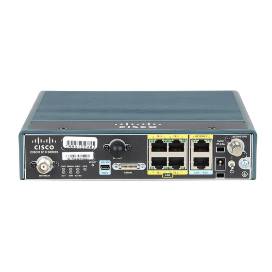
Product Overview General Description The Cisco 819 ISR is a standard form factor with a commercial operating range. The 3G Cisco 819 ISRs support the 3G speeds (High-Speed PacketAccess Plus [HSPA+] enabling up to 4G speeds and Evolution Data Optimized [EVDO Rev A]). They are backward-compatible with High-Speed Packet Access (HSPA), Universal Mobile Telecommunications Service (UMTS), Enhanced Data Rates for Global Evolution (EDGE), General Packet Radio Service (GPRS), and EVDO Rev 0/1xRTT. - Page 21 Chapter 1 Product Overview General Description Figure 1-2 Cisco 819HGW Integrated Services Router Figure 1-3 shows the front panel details of the Cisco 819HG ISR. Figure 1-3 Cisco 819HG ISR Front Panel 3G main antenna FE ports LEDs GE WAN port...
- Page 22 10 5 VDC molex power input 11 Power switch Diversity/GPS antenna 12-in-1 serial port 12 Ground Figure 1-4 shows the front panel details of the Cisco 819HGW ISR. Figure 1-4 Cisco 819HGW ISR Front Panel 3G main antenna FE ports LEDs...
-
Page 23: Sku Information
13 Ground Serial port FE ports SKU Information Table 1-1 lists the different 3G SKUs available for the Cisco 819HG and Cisco 819G ISRs. All SKUs support external antenna. WLAN is not supported. Note Table 1-1 Supported 3G SKUs for Cisco 819HG and Cisco 819G ISRs... - Page 24 Chapter 1 Product Overview SKU Information Table 1-1 Supported 3G SKUs for Cisco 819HG and Cisco 819G ISRs(continued) SKU ID Description C819HG-B-K9 Compact Hardened 3G IOS Router with Bharat generic EVDO Rev A based on MC5728V C819G+7-K9 C ompact Non-hardened 3G IOS Router with Global HSPA + Release 7...
- Page 25 Chapter 1 Product Overview SKU Information Table 1-2 lists the different SKUs available for the Cisco 819HGW, Cisco 819H, and Cisco 819HWD ISRs. Table 1-2 Supported SKUs for Cisco 819HGW, Cisco 819H, and Cisco 819HWD ISRs WiFi External Antenna SKU ID...
- Page 26 Chapter 1 Product Overview SKU Information Table 1-3 lists the different 4G LTE SKUs available for the Cisco 819HG and Cisco 819G ISRs. Table 1-3 Supported 4G LTE SKUs for the Cisco 819HG-4G and Cisco 819G-4G ISRs SKU ID Mode...
- Page 27 Chapter 1 Product Overview SKU Information Table 1-3 Supported 4G LTE SKUs for the Cisco 819HG-4G and Cisco 819G-4G ISRs (continued) SKU ID Mode Operating Regions Frequency Band Description C819HG-4G-G-K9 LTE—HSPA+/ Global 800 MHz (band 20)/900 MHz Hardened Cisco 819...
-
Page 28: Hardware Features
Version = 10 PRI SKU ID = 535479 Carrier ID = 29 Carrier Name = Tata Current Modem Temperature = 30 degrees Celsius Endpoint Port Map = 75 Router# Hardware Features This section provides an overview of the following hardware features for the Cisco 819 ISR. • Platform Features for Cisco 819 ISRs, page 1-11 •... -
Page 29: Platform Features For Cisco 819 Isrs
The WAAS Express feature is not supported. This feature will be supported for 3G and 4G interfaces Note with later IOS releases. Platform Features for Cisco 819 ISRs Table 1-4 lists the platform features comparison for the Cisco 819 ISRs. Table 1-4 Cisco 819 ISRs Platform Features Cisco 819HG Cisco 819HGW... -
Page 30: Antennas
Certification Authority stored on the router. Antennas The Cisco 819 3G routers provide two standard panel-mount TNC connectors to support the 3G antenna and the diversity and GPS external antenna. The main antenna is used for the primary 3G antenna. The second can be used as a diversity receive only 3G antenna or GPS antenna that does not require power supply from the router. -
Page 31: Power Switch
Module is transmitting or receiving. Module is not powered. Green (solid) Standalone GPS. Green (slow blinking) GPS is acquiring. Yellow (solid) Assisted GPS. Yellow (slow blinking) Assisted GPS is acquiring. GPS is not configured. Cisco 819 Integrated Services Router Hardware Installation Guide 1-13 OL-23125-02... - Page 32 2. There is only one LED to indicate the status of two SIMs. A one-blink pattern represents the status of the SIM in slot 0, followed by a two-blink pattern for the SIM in slot 1. Table 1-6 describes the WLAN LEDs for the Cisco 819HGW and Cisco 819HWD ISRs. Cisco 819 Integrated Services Router Hardware Installation Guide 1-14...
- Page 33 Bad MAC address. Ethernet failure during the image recovery. Boot environment failure. No Cisco image file. Boot failure. Cisco IOS errors Software failure. Try to disconnect and reconnect the unit power. Cisco 819 Integrated Services Router Hardware Installation Guide 1-15 OL-23125-02...
- Page 34 Chapter 1 Product Overview Hardware Features Table 1-7 describes the 4G LTE LEDs for the Cisco 819 ISR. Table 1-7 4G LTE LED Descriptions Color Description Yellow FPGA download is complete. Green (blinking) ROMMON is operational. Green (solid) IOS is operational.
-
Page 35: Memory
No Service. Memory The Cisco 819HG and Cisco 819G ISRs uses non-upgradable flash memory and main memory. The onboard flash memory contains the Cisco IOS software image and the boot flash contains the ROMMON boot code. Table 1-8 lists the memory requirements for Cisco 819 ISRs. -
Page 36: Embedded 3G Modem
Embedded 4G LTE Modem The Cisco 819HG-4G and Cisco 819G-4G routers have an embedded 4G LTE modem provided by Sierra Wireless. The Verizon SKUs come with an MC7750 modem, the AT&T SKUs come with an MC7700 modem, and the Global SKUs come with an MC7710 modem. -
Page 37: Supported Cisco Antennas And Cables
Hardware Features Supported Cisco Antennas and Cables The Cisco 819 ISR provides two standard panel-mount TNC connectors to support the 3G antenna and the diversity and GPS external antenna. The main antenna is used for the primary 3G antenna. The second can be used as a diversity receive only 3G antenna or GPS antenna that does not require power supply from the router. - Page 38 Chapter 1 Product Overview Hardware Features Table 1-11 lists the supported Cisco WiFi antenna for Cisco 819HGW and Cisco 819HWD ISRs. Table 1-11 Supported Cisco WiFi Antenna Frequency Mounting Peak Gain Peak Gain Antenna band(s) Mechanical IP Rating 2.4 GHz (dBi)
- Page 39 Chapter 1 Product Overview Hardware Features Table 1-12 lists the Cisco 4G LTE antennas that are supported for use on Cisco 819 ISRs. Table 1-12 Supported 4G LTE Antennas Maximum Gain and Cisco Part Number Description Frequency Ranges Description 4G-LTE-ANTM-D...
- Page 40 50 ft (15.24 m) 3.4 dB 2400 (one RP-TNC plug, 5.75 dB 5800 one RP-TNC jack) Table 1-15 Cisco Extension Cables for Use with 4G LTE Antennas Maximum Insertion Cisco Product Number Cable Length Loss Frequency (MHz) Color Plenum Rated?
-
Page 41: Serial Port
1. Cable can be routed within building plenum spaces. Serial Port The Cisco standard High Speed Smart Serial 12-in-1 connector allows the highest flexibility of connections to various DTE/DCE devices. The 12-in-1 serial interface pins connect to the FPGA. The FPGA configures the pin directions based on the cable type used. -
Page 42: Power Supply
12-in-1 Serial Port Power Supply All SKUs require a 5 VDC power source. Cisco 819HG and Cisco 819G ISRs have a self-locking Molex mini-fit connector. Cisco 819HGW and Cisco 819HWD ISRs use a 5.5 mm barrel-type connector with separate locking clip. An external AC power adapter is supported by default. The optional external power adapters are available to support a variety of DC power sources, suitable for fixed, vehicle, or railway installations. -
Page 43: Dc Power Adapters
A 1.3-meter long output cable connects to the router. Accessories Table 1-16 lists the accessories available for the Cisco 819 ISRs. For a complete list of SKUs that support these accessories, see the “Platform Features for Cisco 819 ISRs”section on page 1-11. - Page 44 Chapter 1 Product Overview Hardware Features Cisco 819 Integrated Services Router Hardware Installation Guide 1-26 OL-23125-02...
-
Page 45: Installing The Router
C H A P T E R Installing the Router This chapter describes the equipment and the procedures for successfully installing the Cisco 819 ISR and contains the following sections: Equipment, Tools, and Connections, page 2-2 • Installing the Router, page 2-4 •... -
Page 46: Chapter 2 Installing The Router
Distribution System. This product may connect to the Cable Distribution System ONLY through a device that is approved for direct connection. Statement 1078 Equipment, Tools, and Connections This section describes the equipment, tools, and connections necessary for installing your Cisco 819 ISR. It contains the following topics: Items Shipped with your Router, page 2-3 •... -
Page 47: Items Shipped With Your Router
Equipment, Tools, and Connections Items Shipped with your Router Unpack the box and verify that all items listed on the invoice were shipped with the Cisco 819 ISR. The following items are shipped with your router: AC power supply (default) •... -
Page 48: Ethernet Devices
If you plan to connect a modem, provide the modem and modem cable. Installing the Router This section describes how to install the Cisco 819 ISR. These routers can be installed on a table top or other flat horizontal surface mounted on a wall or DIN rail. -
Page 49: Accessing The Sim Card
Caution Warning Hot surface. Statement 1079 To access the SIM card in the Cisco 819 ISR, follow these steps: Power off the router and disconnect the power cable from the power source. Step 1 Place the router on its side and ensure that any installed antennas are carefully oriented. -
Page 50: Installing Antennas
Replace the panel and the screws. Step 5 Installing Antennas Before you install the Cisco 819 ISR on a table, wall, or DIN rail, install the antennas on the front panel. Note It is difficult to install the antennas after the router is installed. -
Page 51: Installing A Wifi External Antenna
Rotate the knurled portion of the WiFi external antenna clockwise to screw the antenna to the RP-TNC. Step 2 (See Figure 2-3.) WiFi antennas should be generally perpendicular to each other to achieve best coverage. Note Cisco 819 Integrated Services Router Hardware Installation Guide OL-23125-02... -
Page 52: Installing On A Table
2-12. Mounting on a Wall The Cisco 819 ISR has mounting holes on the bottom of the chassis for mounting the unit on a wall or other vertical surface. The attachment hardware is provided. Cisco 819 Integrated Services Router Hardware Installation Guide... - Page 53 The screws must be long enough to penetrate at least 1.0 inch (25.4 mm) into the supporting wood or metal wall stud. (See Figure 2-5.) The orientation of the Cisco 819 ISR products is critical when wall-mounting. The router must Note be oriented as shown in Figure 2-5 with the left side of the router rotated up (as viewed from the IO side) to comply with IP41 and safety criteria.
-
Page 54: Installing A Din Rail
IP 41, cables should be routed down relative to the router to prevent water from travelling on the cables. Installing a DIN Rail You can use either the 7.5-mm or the 15-mm thick DIN rail for the Cisco 819 ISR. Secure the DIN rail to the mounting surface approximately every 7.8 inches (200 mm) and use end-anchors appropriately. - Page 55 Chapter 2 Installing the Router Installing the Router To attach the Cisco 819 ISR to a 35-mm wide DIN rail, follow these steps. Attach the DIN rail to the back of the router using the three screws provided. (See Figure 2-6.)
-
Page 56: Installing The Router Ground Connection
Installing the Router Installing the Router Figure 2-8 Cisco 819 ISR Installed with the DIN Rail Installing the Router Ground Connection The router must be connected to a reliable earth ground. Install the ground wire in accordance with local electrical safety standards. -
Page 57: Installing The Power Cord Retention Lock
Installing the Power Cord Retention Lock The Cisco 819 ISRs have a power cord retention mechanism as an accessory. It locks the power cord to the router so when a user accidentally pulls out the power cord, the power cord will not come out from the router. - Page 58 Figure 2-12. Cisco 819 Integrated Services Router Hardware Installation Guide 2-14 OL-23125-02...
-
Page 59: Installing The Power Switch Lock
Installing the Power Switch Lock The Cisco 819 ISRs have a power switch lock as an accessory. The power switch lock prevents unauthorized access to a tampered proof router (for example, router in a bus). For the complete list of... - Page 60 Installing the Router Figure 2-14 Installing Power Switch Lock Ring terminal Power switch lock Power switch lock washer Pan-head screw Power switch lock standoff Figure 2-15 Power Switch Lock Installed Cisco 819 Integrated Services Router Hardware Installation Guide 2-16 OL-23125-02...
-
Page 61: Mounting The Dc Power Supply
Statement 378 The Cisco 800 ISR DC power supply may be mounted to a wall using four #6 pan- or round-head wood screws for the mounting holes on the supply. - Page 62 Installing the Router Mounting the DC Power Supply The DC supply is IP 41 compliant in all six orthogonal directions. The mounting orientation will Note not affect IP 41 compliance. Cisco 819 Integrated Services Router Hardware Installation Guide 2-18 OL-23125-02...
-
Page 63: Preparing To Connect The Router
C H A P T E R Connecting the Router This chapter describes how to connect Cisco 819 Integrated Services Router (ISRs) to Ethernet devices and a network. The chapter contains the following sections: Preparing to Connect the Router, page 3-1 •... -
Page 64: Chapter 3 Connecting The Router
PC, server, or workstation. (Optional) Connect additional servers, PCs, or workstations to the other Ethernet switch ports. Step 3 Use the Cisco Configuration Express to configure the Internet connection settings. See Note Cisco Configuration Professional Quick Start Guide for more information. - Page 65 Available port on the external Ethernet switch Connect the other end of the cable to the available port on the Ethernet switch to add additional Ethernet Step 2 connections. Step 3 Turn on the Ethernet switch. Cisco 819 Integrated Services Router Hardware Installation Guide OL-23125-02...
-
Page 66: Connecting A Terminal Or Pc To The Console Port
Some laptops and PCs do not come with DB-9 serial port connectors and may require a Note USB-to-serial port adapter. To communicate with the router, start a terminal emulator application. Step 3 Cisco 819 Integrated Services Router Hardware Installation Guide OL-23125-02... -
Page 67: Terminal Emulator Settings
Make sure that your modem and the router console port are configured for the same transmission speed Step 4 (up to 115200 b/s is supported) and support mode control with data carrier detect (DCD) and data terminal ready (DTR). Cisco 819 Integrated Services Router Hardware Installation Guide OL-23125-02... -
Page 68: Connecting The Ac Adapter
This product requires short-circuit (overcurrent) protection, to be provided as part of the building installation. Install only in accordance with national and local wiring regulations. Statement 1045 To connect your Cisco 819 ISR to an AC power outlet, follow these steps: Connect the AC adapter to an AC power outlet. - Page 69 Connecting the Router Connecting the DC Adapter To connect the DC power on your Cisco 819 ISR, follow these steps: Connect the black and white lead wires to a 12 VDC source. The black lead is negative or ground and Step 1 the white lead is positive.
-
Page 70: Verifying Connections
ROMMON is operational. After powering up, when FPGA is being downloaded (in ROMMON). Green Network activity on FE Switch ports, GE WAN port, 3G cellular interface, and serial interfaces. No network activity. Cisco 819 Integrated Services Router Hardware Installation Guide OL-23125-02... -
Page 71: Chapter 4 Initial Configuration
• Cisco Configuration Professional Express After you connect the cables and power up the router, we recommend that you use the Cisco CP Express web-based application to configure the initial router settings. For instructions on how to use Cisco CP Express to configure the router, see Cisco CP Express User’s... -
Page 72: Cisco Configuration Professional Express
This feature requires the one-time use of the username "username1" with the password "password1." The default username and password have a privilege level of Please change these publicly known initial credentials using Cisco CP Express or the Cisco IOS CLI. -
Page 73: Setup Command Facility
Would you like to enter basic management setup? [yes/no]: yes Enter a hostname for the router (this example uses Router). Step 5 Configuring global parameters: Enter host name [Router]: Router Cisco 819 Integrated Services Router Hardware Installation Guide OL-23125-02... - Page 74 5 $1$D5P6$PYx41/lQIASK.HcSbfO5q1 enable password xxxxxx line vty 0 4 password xxxxxx snmp-server community public no ip routing interface FastEthernet0 no shutdown speed 100 duplex auto ip address 172.16.2.3 255.255.0.0 Cisco 819 Integrated Services Router Hardware Installation Guide OL-23125-02...
-
Page 75: Verifying The Initial Configuration
Verify the initial configuration. See the “Verifying the Initial Configuration” section on page 4-5 verification procedures. After the initial configuration file is created, you can use the Cisco IOS CLI to perform additional configuration. Verifying the Initial Configuration To verify that the new interfaces are operating correctly, perform the following tests: To verify that the interfaces and line protocol are in the correct state—up or down—enter the show... - Page 76 Chapter 4 Initial Configuration Verifying the Initial Configuration Cisco 819 Integrated Services Router Hardware Installation Guide OL-23125-02...
-
Page 77: Appendix
Table A-1 lists the operational limits of the Cisco 819 ISR. Operating the router outside of the limits specified is not supported. For the complete list of SKUs available for each Cisco 819 ISRs, see the “SKU Information” section on page 1-5. -
Page 78: Appendix A Technical Specification
Heavy-Duty Vehicle SAE J1455 Operating Random Vibe, Cab Mounted Truck Applications SAE J1455 Operating Sinusoidal Vibe, Category 3 SAE J1455 Non-operating Sinusoidal Vibe, Category 3 SAE J1455 Handling Drop Test Certifications Cisco 819 Integrated Services Router Hardware Installation Guide OL-23125-02... - Page 79 PWRx-20W-12VDC (10 VDC to 36 VDC operating range) 24 VDC nominal PWRx-20W-24VDC (18 VDC to 75 VDC operating range) Maximum Power 25 W Consumption Maximum Output Power 20 W Rating (5 VDC, 4 Amps) Cisco 819 Integrated Services Router Hardware Installation Guide OL-23125-02...
- Page 80 — — EN50155 (EN61373) and RIA20 Maximum Power — — 25 W Consumption Maximum Output Power — — 20 W Rating Operating Temperature — — –13 to 140°F (–25 to 60°C) Cisco 819 Integrated Services Router Hardware Installation Guide OL-23125-02...
-
Page 81: Mean Time Between Failure Ground Benign Environment
Mean Time Between Failure Ground Benign Environment Table A-2 lists the Mean Time Between Failire (MTBF) values for Cisco 819 ISRs. The MTBF is calculated based on the Ground Benign condition. The values may be adjusted based on the different router usage. -
Page 82: Supported Power Adapters
Supported Power Adapters Table A-3 Table A-4 list the supported power adapters for Cisco 819 ISRs. The PWR1 AC and DC adapters uses molex connector while PWR2 uses barrel-type connector. Note The 24 VDC and Martek power adapters will be available on Q1CY13... - Page 83 24 VDC — — — — 0500-B/V1 Martek MBRH 52 VDC — — — — 0500-C/V1 Martek MBRH 72 VDC — — — — 0500-D/V1 Martek MBRH 24 VDC — 0500-B/V2 Cisco 819 Integrated Services Router Hardware Installation Guide OL-23125-02...
- Page 84 C819H-K9 Nominal Input Power Adapter Range (4G LTE SKUs) (3G SKUs) (3G + WiFi SKUs) (WiFi SKUs) (Serial SKU) Martek MBRH 52 VDC — 0500-C/V2 Martek MBRH 72 VDC — 0500-D/V2 Cisco 819 Integrated Services Router Hardware Installation Guide OL-23125-02...
Need help?
Do you have a question about the 819 and is the answer not in the manual?
Questions and answers