Table of Contents
Advertisement
Quick Links
Advertisement
Table of Contents

Related Manuals for Agilent Technologies U4002A


Summary of Contents for Agilent Technologies U4002A
- Page 1 Artisan Technology Group is your source for quality new and certified-used/pre-owned equipment SERVICE CENTER REPAIRS WE BUY USED EQUIPMENT • FAST SHIPPING AND DELIVERY Experienced engineers and technicians on staff Sell your excess, underutilized, and idle used equipment at our full-service, in-house repair center We also offer credit for buy-backs and trade-ins •...
- Page 2 Agilent Digital Test Console Installation Guide Agilent Technologies...
- Page 3 Notices Manual Notices © Agilent Technologies, Inc. 2009- 2011 Warranty No part of this manual may be reproduced The material contained in this docu- This manual provides these notices: in any form or by any means (including ment is provided “as is,” and is sub-...
- Page 4 Standards and Technology to the extent exist even with the equipment switched With the U4002A 2-slot chassis, do not allowed by that organization's calibration off. To avoid dangerous electrical shock, DO stack more than five chassis.
- Page 5 Spectrum Management Agency of Aus- tralia. This signifies compliance with the Australia EMC Framework regulations Operate the U4002A 2-slot chassis in the under the terms of the Radio Communica- horizontal orientation. Do NOT operate this tion Act of 1992.
-
Page 6: Table Of Contents
Rackmounting Ventilation Static Electricity To manage cables Step 2: Set up the U4002A 2-slot chassis To rackmount the U4002A 2-slot chassis To set up a portable U4002A 2-slot chassis Step 3: Insert and remove blades To insert a blade into the chassis... - Page 7 3 Software Installation 4 For More Information On the U4301A PCIe Analyzer Blade On the U4998A HDMI Tester Blade 5 Characteristics Standards Environmental Electrical Mechanical Calibration Connectors Chassis Manager To contact us ... Index Agilent Digital Test Console Installation Guide...
-
Page 8: Introduction
Agilent Digital Test Console Installation Guide Introduction About the Agilent Digital Test Console U4002A 2-Slot Chassis Chassis Manager System Controller Application Blade Agilent Technologies... -
Page 9: About The Agilent Digital Test Console
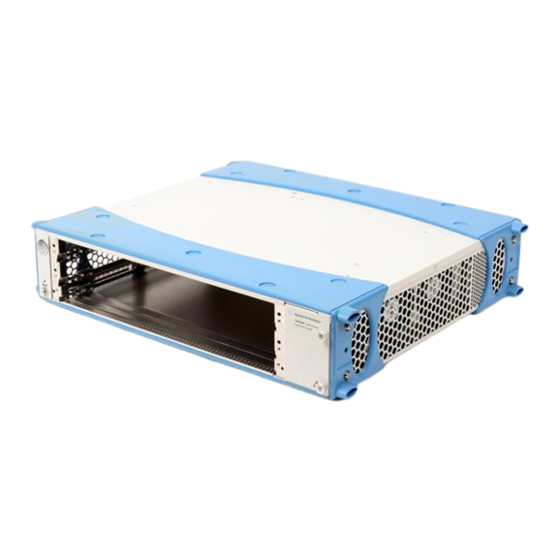
These chassis models are available: • U4002A — a portable 2-slot chassis U4002A 2-Slot Chassis Designed for portable or small system testing, the U4002A 2-slot chassis comes with the following: • a removable plastic handle • optional transit case •... -
Page 10: Chassis Manager
• synchronizes timing across all blades through an Agilent Test Bus • synchronizes timing with an internal or external clock source The chassis manager is factory-installed into the bottom slot of the U4002A 2-slot chassis. This chassis managers is available: • U4002-00101 — Chassis manager with PCIe and USB. Agilent... -
Page 11: System Controller
Introduction System Controller The Agilent Digital Test Console requires a system controller PC. A system controller centrally configures and reports test results from multiple chassis. The system controller PC communicates with a chassis via the chassis manager’s PCIe interface, so the system controller must have a PCIe interface. -
Page 12: Application Blade
Introduction Application Blade An application blade connects to a System Under Test (SUT), injects test data, and makes real-time measurements. Application blades in the Agilent Digital Test Console have the following common components: OOS (Out of Service) Indicates blade health: •... - Page 13 Introduction Agilent Digital Test Console Installation Guide...
-
Page 14: Hardware Installation
Installation Guide Hardware Installation Overview Step 1: Plan the installation Step 2: Set up the U4002A 2-slot chassis Step 3: Insert and remove blades Step 4: Set up a system controller Step 5: Power up the system Step 6: Troubleshoot problems... -
Page 15: Overview
Step 2: Set up the U4002A 2-slot chassis. If you are using the U4002A 2-slot chassis in a portable application, attach the plastic bumpers and handle. If you are using it in a lab, attach the rackmount brackets and mount onto a rack. -
Page 16: Step 1: Plan The Installation
Rackmounting The following rackmounting options are possible: • 4-post rack—With the U4002A 2-slot chassis, the brackets are provided separately (N5650-00035) and must be attached to the chassis before rackmounting. • 4-post shelf—You can order a kit (E3664AC), which provides rails that attach to the front and back posts in a 4-post rack, forming a shelf onto which you can slide the chassis. -
Page 17: Ventilation
To minimize electrostatic damage, take the necessary anti-static precautions. Both chassis provide a grounding terminal, to which you can connect a wrist strap. To locate this terminal, see “U4002A 2-Slot Chassis" on page Agilent Digital Test Console Installation Guide... -
Page 18: To Manage Cables
Hardware Installation To manage cables The Agilent Digital Test Console has high-density blades that provide many connectors, each of which can have an attached cable. To facilitate the insertion and removal of blades, neatly route cables around the chassis. Doing this enables you to insert and remove blades without having to navigate a web of cables crossing the fronts of blades. -
Page 19: Step 2: Set Up The U4002A 2-Slot Chassis
Step 2: Set up the U4002A 2-slot chassis To rackmount the U4002A 2-slot chassis The U4002A 2-slot chassis ships with plastic bumpers that slide onto the front and back of the chassis, and a handle that attaches to the bumpers on the left side of the chassis. - Page 20 Hardware Installation To attach the 2-slot brackets The U4002A 2-slot chassis ships with brackets (N5650-00035) that attach to the sides of the chassis and front two posts of a 4-post rack. Use a Torx T10 screwdriver with a torque of 1.37 Nm or 14 kgf-cm (12.15 lbs-in) to attach the two rackmount brackets to both sides of the...
-
Page 21: To Set Up A Portable U4002A 2-Slot Chassis
Do not operate in a vertical orientation. To begin using the U4002A 2-slot chassis, you need to connect the system controller. For details, see “Step 4: Set up a system controller" on page The following options are also available for the U4002A 2-slot chassis: •... - Page 22 Hardware Installation To attach the bumpers If the U4002A 2-slot chassis does not have its plastic bumpers (for example, it was previously rackmounted), you must install them first. For instructions, see “To attach the bumpers" on page Align the bumper with the front of the chassis and make sure that the bumper feet are facing the bottom of the chassis.
-
Page 23: Step 3: Insert And Remove Blades
Hardware Installation Step 3: Insert and remove blades The blades are not hot swappable: You must power down the chassis to insert or remove blades. Empty Slots—Do not operate the chassis with empty slots. • C AUTIO N Always insert a filler blade (N5650-00080) or application blade into empty slots. -
Page 24: To Insert A Blade Into The Chassis
Hardware Installation To insert a blade into the chassis The chassis has guide rails for each slot in the chassis: Guide Slot rail number If there are blades that will be removed often, insert them into the topmost slots. For tips on keeping cables tidy, see “To manage cables"... - Page 25 Hardware Installation Push the blade into the chassis. For application blades, push until the ejector levers are pressed up against the chassis. Nudge the blade gently to allow the levers to engage. Using your thumbs, press inwards firmly until the blade is seated firmly in the backplane.
-
Page 26: To Remove A Blade From The Chassis
Hardware Installation Tighten the retaining screws on either end of the blade. Blades are grounded through the chassis. Tightening the retaining C AU T ION screws ensures the ground connection. To remove a blade from the chassis Loosen the retaining screws on both ends of the blade. For application blades, extend the ends of both levers, by pulling them inwards towards each other. -
Page 27: Step 4: Set Up A System Controller
Hardware Installation Step 4: Set up a system controller The system controller is typically a laptop PC with an ExpressCard PCIe adapter, but it could also be a desktop PC or any other PC with a PCIe interface. To set up a laptop controller laptop controller chassis... -
Page 28: Step 5: Power Up The System
Hardware Installation Step 5: Power up the system To power up the U4002A 2-slot chassis Insert the AC power cord into the inlet at the rear of the chassis. Plug the power cord into a power source. Push the circuit breaker to the right, which is the ON position. -
Page 29: To Power Down The Chassis
Hardware Installation To power down the chassis To power down the chassis, press the power button. The blue LED in the power button turns off and the cooling fans stop rotating. Powering down a chassis places it in standby mode. The W AR N I NG chassis still receives electrical current and can pose an electrical shock risk (for example, in the event of flooding). -
Page 30: Step 6: Troubleshoot Problems
Hardware Installation Step 6: Troubleshoot problems When you power up the chassis, the chassis does the following: • Lights the blue LED inside the power button. • Rotates the cooling fans. • Boots up and runs the chassis manager. • Boots up any inserted application blades. To troubleshoot powerup problems If the chassis or a blade does not appear to have power, check the following:... -
Page 31: To Diagnose Leds
Hardware Installation To diagnose LEDs The LEDs on the chassis manager use the following LEDs during powerup. Blade Color When lit, indicates ... chassis manager STATUS Green The chassis manager has powered up, passed its self test, and detects no serious problems in the chassis. -
Page 32: Software Installation
PC, double-click the .exe file, and follow its installation instructions. Application Software Troubleshooting There are known problems with PCI Express bus enumeration on some controller PCs. For the latest list of known good controller PCs, see the Agilent web site at: www.agilent.com/find/dtc-controllers Agilent Technologies... - Page 33 Software Installation Agilent Digital Test Console Installation Guide...
-
Page 34: For More Information
Agilent Digital Test Console Installation Guide For More Information On the U4301A PCIe Analyzer Blade On the U4998A HDMI Tester Blade Agilent Technologies... -
Page 35: On The U4301A Pcie Analyzer Blade
For More Information On the U4301A PCIe Analyzer Blade For information on probing a PCI Express device under test, refer to the Hardware and Probing for PCI Express Gen3 User's Guide which is included in electronic format with the application software (and on the Agilent web site at www.agilent.com/find/pcie3manuals). -
Page 36: On The U4998A Hdmi Tester Blade
For More Information On the U4998A HDMI Tester Blade You can install the U4998A HDMI Tester blade in the U4002A 2-slot chassis. The blade provides features for testing the HDMI sink and source devices. You can use it to perform HDMI compliance testing and debugging on HDMI devices. - Page 37 For More Information Agilent Digital Test Console Installation Guide...
-
Page 38: Characteristics
Agilent Digital Test Console Installation Guide Characteristics Standards Environmental Electrical Mechanical Calibration Connectors To contact us ... Agilent Technologies... -
Page 39: Standards
5° to 40° C (41°F to 104°F) Storage up to 90% non-condensing, 12 hr max, -25° to 60° C (-13°F to 140°F) Safety Conditions Installation Category Pollution Degree Electrical U4002A 2-slot Input Voltage 100 - 240 VAC nominal chassis Power Consumption 800 VA Frequency... -
Page 40: Mechanical
Characteristics Mechanical U4002A 2-slot Width 432 mm (17”) chassis Height 2U — 87 mm (3.5“) Depth 414 mm (16.3”) Weight 7.7 kg (17 lbs) — with only chassis manager installed chassis manager Width 15.2 mm (0.6”) Height 322.25 mm (12.7”) Depth 280 mm (11”) -
Page 41: Connectors
Characteristics Connectors Chassis Manager For introductory information about how the connectors are used, see “Chassis Manager" on page 9. PCIe Agilent PCIe • PCI Express x4 • Gen 1 and Gen 2 compliant AGILENT TEST BUS • USB 2.0 Type B, not supported in initial release. AGILENT TEST BUS •... -
Page 42: To Contact Us
Characteristics To contact us ... Should you require technical assistance, contact the center in your region. See: http://www.agilent.com/find/contactus Agilent Digital Test Console Installation Guide... - Page 43 Characteristics Agilent Digital Test Console Installation Guide...
-
Page 44: Index
U4002A 2-slot chassis, blades grounding terminal, hot swapping, U4002A 2-slot chassis, inserting, bumpers, for 2-slot rackmount brackets attaching, attaching to U4002A 2-slot chassis, removing, re-calibration, H/S, see Hot Swap LED reset button Hot Swap LED application blade, application blade, RS232 port... - Page 45 Index technical support, temperature characteristics, trigger chassis manager, connectors, U4002-00101, U4002-60002, U4002A, U4002A 2-slot chassis, accessories pouch, mechanical characteristics, power requirements, powering up, proper orientation, rackmounting, U4998A HDMI Tester blade, chassis manager, connectors, ventilation, wrist strap, Agilent Digital Test Console Installation Guide...
- Page 46 Artisan Technology Group is your source for quality new and certified-used/pre-owned equipment SERVICE CENTER REPAIRS WE BUY USED EQUIPMENT • FAST SHIPPING AND DELIVERY Experienced engineers and technicians on staff Sell your excess, underutilized, and idle used equipment at our full-service, in-house repair center We also offer credit for buy-backs and trade-ins •...