Table of Contents
Advertisement
Quick Links
Advertisement
Table of Contents

Related Manuals for Furman PS-PRO


Summary of Contents for Furman PS-PRO
- Page 1 P S - P R O - P O W E R C O N D I T I O N E R / S E Q U E N C E R...
-
Page 2: Installation
P S - P R O - P O W E R C O N D I T I O N E R / S E Q U E N C E R Congratulations on your purchase of a Furman PS-PRO Power Conditioner/Sequencer. The PS-PRO is one of Furman’s top-of-the-line PRO Series, offering maximum protec- tion from the AC line hazards faced by delicate analog and digital pro audio and video... - Page 3 The front panel outlet is limited to 15 amp use. The PS-PRO also uses a 20 amp line cord, which can be recognized by the perpendicular blades on the plug. In 20 amp products, use of a plug of this type is required for UL safety certification.
-
Page 4: Local Control
Furman’s AC Line Voltage Regulators in addition to the PS-PRO. If you do use a voltage regulator, run the raw power line into the regulator first so that the PS-PRO receives a stabilized voltage to distribute. -
Page 5: Remote Control
PS-PRO. If an additional wire is used, an LED may also be installed at the remote end to indicate that the power is on. -
Page 6: Front Panel
PRO, this indicator will be lit if the unit is receiving below 80 volts or more than 140 volts, and power will not be applied to the PS-PRO’s outlets. If the unit has been operating with an acceptable input voltage and then the voltage goes out of the ac-... -
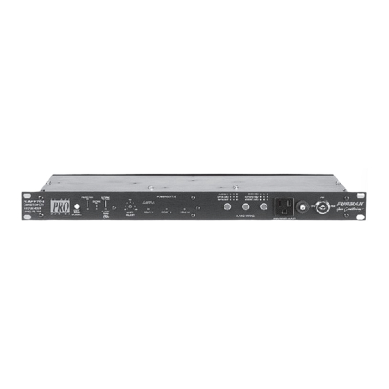
Page 7: Rear Panel
Delay Adjust control on the front panel. TERMINAL STRIP: Allows one or more switches to be connected to turn the PS-PRO on and off from a re- mote location. Two, and sometimes three, wires are CIRCUIT BREAKER: The overall capacity of the PS-PRO is 20 amps. -
Page 8: Momentary Mode
MOMENTARY MODE In Momentary Mode (jumper plug installed on JMP2) The PS-PRO has “memory” — it only needs a momentary signal from the remote switch to change its state from ON to OFF. When first plugged in (or after power is lost and reapplied for any reason) the stored state is OFF, and the DELAY 1 LED will flash. - Page 9 ON position check the polarity and reverse the LED leads if needed. FLASHING DELAY 1 INDICATOR The DELAY 1 LED on a PS-PRO flashes to indicate that a remote switch is off or not connected. In Maintained Mode (JMP1, MAINT ON’s jumper plug is installed), this will only occur when the REM terminal is tied to the +12V terminal.
- Page 10 If this does occur, most likely damage will be limited to the PS-PRO itself and will affect only certain spike suppression components (called varistors or MOV’s.) In this “suicide” mode,...
- Page 11 P S - P R O - P O W E R C O N D I T I O N E R / S E Q U E N C E R the purchase date (if a Warranty Registration Card was mailed in at the time of purchase, this is not necessary).
- Page 12 PS-PRO SPECIFICATIONS Current rating: Input Voltage: Mains Wiring analyzer: Detects one normal mode and five fault modes Delay Intervals: ON sequence: OFF sequence: Remote Switch: Spike Protection Modes: Line to neutral, neutral to ground, line to ground Clamping Voltage, all modes:...
Need help?
Do you have a question about the PS-PRO and is the answer not in the manual?
Questions and answers