Table of Contents
Advertisement
Advertisement
Table of Contents

Related Manuals for A&D SV-10


Summary of Contents for A&D SV-10
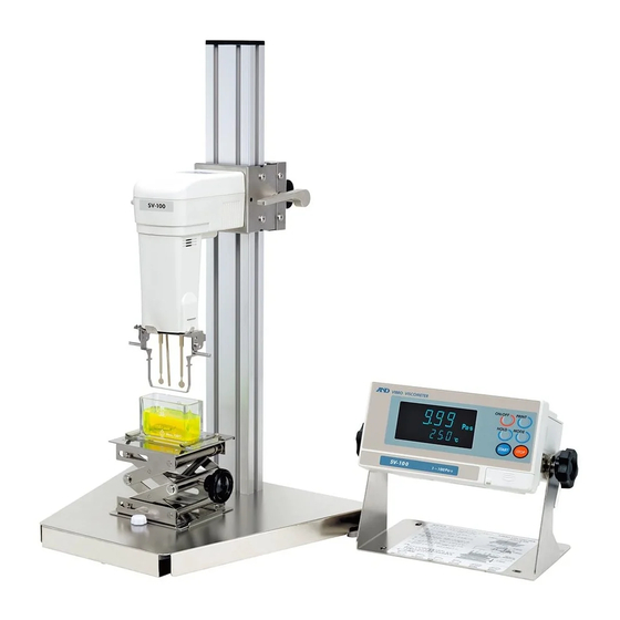
- Page 1 SV-10 SV-100 Vibro Viscometer INSTRUCTION MANUAL 1WMPD4000646E...
- Page 2 © 2008 A&D Company Ltd. All rights reserved. No part of this publication may be reproduced, transmitted, transcribed, or translated into any language in any form by any means without the written permission of A&D Company Ltd. The contents of this manual and the specifications of the instrument covered by this manual are subject to change for improvement without notice.
-
Page 3: Table Of Contents
6-1 Notes on Viscosity Calibration......................21 6-2 Calibration Procedure........................22 6-2-1 One-point Calibration......................... 23 6-2-2 Two-point Calibration......................... 24 6-2-3 Simplified Calibration Using Purified Water (SV-10 only)............26 7. FUNCTION SETTING........................28 7-1 Operation............................28 7-2 Details of the Function Items ......................30 7-3 Description of Items.......................... - Page 4 8. CONNECTION TO A PERSONAL COMPUTER................49 9. CONNECTION TO A PRINTER ....................48 10. RS-232C SERIAL INTERFACE ....................51 11. COMMAND LIST.........................52 12. TROUBLESHOOTING ........................53 13. ERROR DISPLAY ........................57 14. SPECIFICATIONS........................58 15. OPTIONAL ACCESSORIES .......................60 16. EXTERNAL DIMENSIONS ......................64 Whole View ............................64 Detailed View of the Sensor Unit ......................
-
Page 5: Introduction
1. INTRODUCTION This manual describes how the SV series viscometer works and how to get the most out of it in terms of performance. Read this manual thoroughly before using the viscometer and keep it at hand for future reference. 1-1 Compliance Compliance with FCC Rules Please note that this device generates, uses and can radiate radio frequency energy. -
Page 7: Features
Simplified calibration when measuring the viscosity near 1 mPa⋅s, (SV-10 only) Simplified calibration using purified water is a one-key operation. The SV-10 has a built-in function to measure the temperature of the purified water using the temperature sensor and calculates the viscosity value of the purified water at that temperature. -
Page 8: Unpacking The Viscometer
2. UNPACKING THE VISCOMETER 2-1 Unpacking The viscometer is a precision instrument. Unpack the viscometer carefully. Keep the packing material to be used for transporting the viscometer in the future. Accessories Note Please confirm that the AC adapter type is correct for your local voltage and receptacle type. -
Page 9: Installing The Viscometer
2-2 Installing the Viscometer Install the viscometer as follows: 1 Connect the display unit to the main unit using the connection cable. 2 Insert the AC adapter plug into the AC adapter jack located on the rear side of the display unit. Insert the other end of the AC adapter plug into an electrical outlet. -
Page 10: Display And Keys
3. DISPLAY AND KEYS 3-1 Display Name Description Standby mode Displays [- - - - -]. Displays the viscosity value in real Measurement mode Viscosity display time. Freezes the display of the viscosity Data hold mode value. Viscosity units Displays the unit of viscosity. Standby mode Displays the temperature value in real time. -
Page 11: Keys
3-2 Keys Description Turns the power on and off. ON:OFF When the power is turned on, the viscometer enters the standby Power mode ( [- - - - -] is displayed.) START Start a measurement. (The processing indicator blinks.) Displays the viscosity and temperature values in real time during Start measurement. -
Page 12: Displaying The Viscosity Values
The viscosity values are displayed as below, depending on the unit selected and the viscosity range. The correlation of the units are as follows: 1 mPa⋅s = 0.001 Pa⋅s = 1 cP =0.01 P 3-3-1 SV-10 Use the MODE key to switch between mPa⋅s (Millipascal second) and Pa⋅s (Pascal second), or between cP (Centipoise) and P (Poise). -
Page 13: Sv-100
3-3-2 SV-100 Use the MODE key to switch between Pa⋅s (Pascal second) and P (Poise). The unit selected at the factory before shipment is Pa⋅s. Viscosity Unit selected measured Pa⋅s Minimum Minimum Display Display Pa⋅s display display 1.00 10.0 0.01 |... -
Page 14: Precautions
4. PRECAUTIONS To get the optimum performance from the viscometer and acquire accurate measurement data, note the following: 4-1 General Precautions Install the viscometer in an environment where the temperature and humidity are not excessive. The best operating temperature is 25°C±2°C at 45-60% relative humidity. For precise measurement, install the viscometer where there are no great changes in temperature and humidity. -
Page 15: During Use
4-2 During Use To level the surface of the sample; adjust the leveling feet so that the center of the narrow part of the right and left sensor plates is on the liquid surface. The viscosity of a liquid is temperature dependent and changes by negative 2 to negative 10 percent, per degree Celsius. -
Page 16: After Use
4-3 After Use Remove any residual sample material from the sensor plates, temperature sensor and protector using alcohol. Using the sensor plates, temperature sensor and protector with residue of an old sample left on will cause a measurement error. Clean the sensor plates carefully to avoid bending them. The sensor plates and the temperature sensor are made of stainless steel (SUS304). -
Page 17: Measuring The Absolute Value Of Viscosity
4-4 Measuring the Absolute Value of Viscosity The SV Series Sine-wave Vibro Viscometer, as a measuring principle, detects the product of viscosity and density. Displayed viscosity value = Viscosity × Density ⋅ ⋅ ⋅ ⋅ ⋅ [1] While the displayed value has a unit of mPa⋅s, it indicates the product of viscosity and density. Example (1) When a sample has an absolute value of viscosity of 2.00 mPa⋅s and density of 1.000: Displayed value = 2.00 [mPa⋅s] ×... -
Page 18: At Calibration
4-4-2 At Calibration When calibrating, enter the product of the absolute viscosity value and the density of the standard viscosity fluid used for calibration, as a correction value. The standard viscosity fluid has the calculation sheet of kinetic viscosity and viscosity at various temperatures attached. -
Page 19: Measurement
SV-10 Note • Be sure to adjust the sample surface to the center of the narrow part of the sensor plates. Otherwise, a measurement error may occur. • The surface locator plate can be attached or removed by loosening the screw. - Page 20 Note Use the protector in the position as shown on the left below. If the protector is not used with the SV-10, a measurement error may occur, especially in measuring a viscosity over 5000 mPa⋅s. When the position of the sensor plates in the liquid is not at the same level, level the...
-
Page 21: Basic Measurement Procedure
5-2 Basic Measurement Procedure The below is an example of the SV-10 at shipment. For the SV-100, the unit at shipment is Pa⋅s 1 With the power turned off, press the ON:OFF key. When the display is in the standby mode, press the START key. -
Page 22: Changing Units
The unit selected upon power-on depends on the function setting. The unit selected at the factory before shipment is as shown below. Model Viscosity Temperature SV-10 mPa・s °C SV-100 Pa・s Use the MODE key to change units. Each time the MODE key is pressed, units are switched as below: Note that the unit of temperature is fixed in the function setting. -
Page 23: Viscosity Calibration
Be sure to adjust the sample surface to the center of the narrow part of the sensor plates. Otherwise, a measurement error may occur. In the calibration mode, the unit of viscosity for the SV-10 is mPa⋅s, for the SV-100, Pa⋅s. The unit of temperature is fixed to °C. -
Page 24: Calibration Procedure
6-2 Calibration Procedure Note As to the correction value used for one-point calibration and two-point calibration, enter the product of the absolute viscosity value and the density of the standard viscosity fluid. For details, refer to "4-4-2 At Calibration". After calibration, check the values, comparing the product described above with the displayed value. -
Page 25: One-Point Calibration
6-2-1 One-point Calibration The below is an example of the SV-10. For the SV-100, the unit is Pa⋅s In the standby mode, press and hold HOLD enter calibration mode. " Cal " appears. (Standby mode) Select one-point calibration (Cal-1) Press and hold and press the PRINT key to confirm. -
Page 26: Two-Point Calibration
The below is an example of the SV-10. 6-2-2 Two-point Calibration For the SV-100, the unit is Pa⋅s In the standby mode, press and hold HOLD enter calibration mode. " Cal " appears. Select two-point calibration (Cal-2) and press the PRINT key to confirm. - Page 27 When the measurement of the first point has completed, clean the sensor plates, temperature sensor and protector and prepare the second standard viscosity fluid. From the previous page Set standard viscosity fluid 10 Place the second standard viscosity fluid in the sample cup.
-
Page 28: Simplified Calibration Using Purified Water (Sv-10 Only)
6-2-3 Simplified Calibration Using Purified Water (SV-10 only) Place the purified water in the sample cup. Press the START key to measure the purified water. Confirm that the viscosity and temperature values are stabilized. Press and hold the START key. - Page 29 Reference data: Theoretical viscosity value (Viscosity × Density) of the purified water at various temperatures Viscosity × Density (mPa・s) Temperature (°C) 10.0 1.31 11.0 1.27 12.0 1.24 13.0 1.20 14.0 1.17 15.0 1.14 16.0 1.11 17.0 1.08 18.0 1.05 19.0 1.03 20.0 1.00...
-
Page 30: Function Setting
7. FUNCTION SETTING The viscometer, by selecting functions to be used in the function setting, can specify the performance appropriate to the usage. Each function is assigned parameters. The performance of a function is specified by changing the parameter. The parameters saved, even if the power is turned off, are maintained in non-volatile memory. 7-1 Operation The operational procedure of the function setting is as follows: In the standby mode, press and hold the MODE key to enter the function setting mode. - Page 31 Example of the function setting procedure Using the SV-10, to change the setting of "Unit upon power-on (Unit)" to the viscosity: cP (Centipoise) and the temperature: °C (Celsius). In the standby mode, press and hold the MODE key to enter the function setting mode. " Cladj "...
-
Page 32: Details Of The Function Items
Follows the viscosity changes slowly. (Stable values) • Unit mPa⋅s • Unit upon power-on Pa⋅s °C Factory setting: Viscos Temper- SV-10=0 -ity ature mPa⋅s SV-100=1 Pa⋅s °F • With "Comma" selected, the separator for CSV format will Decimal point Comma be ";"... -
Page 33: Description Of Items
7-3 Description of Items Date/Time (Cladj) The upper two digits of the year are not displayed. For example, the year 2003 is displayed as "03". The time is set using the 24-hour system. Do not enter a non-existing date and time. Set the order of the date, the date and time as follows: (Example: To change April 5, 2003, 11:22:33 to June 8, 2004, 12:34:00) In the standby mode, press and hold the MODE... - Page 34 Changing the date The date is changed in the selected displaying order. The following is an example when the order of " y " (Year), " m " (Month) and " d " (Day) is selected. Press the MODE key to select the setting value of "...
- Page 35 Changing the time 12 The current time is displayed. Press the MODE key to display the current date. 13 Press the PRINT key to select the setting value of the hour. (Example:11) 14 Press the START key or HOLD key to change the hour.
- Page 36 While the measurement is being performed using the graphing program RsVisco, unit changes using the MODE key is not available. With the SV-10, for a viscosity over 1000 mPa⋅s, the unit is fixed to Pa⋅s, and for a viscosity over 1000 cP, the unit is fixed to P.
- Page 37 • units. Note With the SV-10, for the viscosity over 1000 mPa⋅s, the unit is fixed to Pa⋅s and for the viscosity over 1000 cP, the unit is fixed to P. Each time the MODE key is pressed, the display is switched between the temperature display and the measurement elapsed time display.
- Page 38 The viscosity value and the temperature are output using the internal resolution.*3 The relation between the measuring unit and the internal resolution is as follows: Viscosity Temperature Model °C °F mPa・s Pa・s Internal SV-10 0.01 0.0001 0.01 0.0001 0.01 0.01 SV-100 resolution 0.01 Measurement Elapsed Time Output (5-at)
- Page 39 Date/time Output (5-td) Parameter Settings Description With D.P. format or CSV format selected, whether or not to No output add the date and time to the measurement data can be selected. • Output For examples of output format, refer to "7-4 Data Output Format Examples".
- Page 40 Setting the ID number In the standby mode, press and hold the MODE key to enter the function setting mode. " Cladj " appears. Press the MODE key to select " id ". Press the PRINT key to enter the ID number setting mode.
- Page 41 Initialization (Clr) Restores the following data to the default setting. Function setting Calibration data After initialization, check the viscosity value and perform calibration as necessary. (Refer to 6. VISCOSITY CALIBRATION"). In the standby mode, press and hold the MODE key to enter the function setting mode.
-
Page 42: Data Output Format Examples
7-4 Data Output Format Examples 7-4-1 A&D Standard Format Used with the printer MODE 1 or MODE 2 when the optional compact printer, AD-8121B is connected. Only the viscosity value is output. SV-10 output format example Viscosity Display Output format... - Page 43 SV-100 output format example Viscosity Display Output format Remarks unit OL,-99999999Pas Below measuring range error Pa・s ST,+00001.00Pas 1.00 Pa ・ Pa・s ST,+00010.00Pas 10.0 Pa・s The digit of 0.01Pa⋅s is always zero. OL,+99999999Pas Above measuring range error Pa・s OL,-99999999 Below measuring range error ST,+000010.0 10.0 P ST,+000100.0...
-
Page 44: Format
With "prt 0" or "prt 1" selected for "Data output mode (prt)", output contents can be selected by the settings of "5-at", "5-td" and "5-ed". With "prt 2" selected for "Data output mode (prt)", only the viscosity value is output Shown below are SV-10 printing examples. Printing format example (1) Function setting (√=Output Blank=No output) -
Page 45: Csv Format
With CSV format selected, the viscosity value and the temperature are output using the internal resolution. The relation between the measuring unit and the internal resolution is as follows: Viscosity Temperature Model °C °F mPa・s Pa・s Internal SV-10 0.01 0.0001 0.01 0.0001 0.01 0.01 SV-100 resolution 0.01... - Page 46 Date/time √ 5-td The output data are 52 characters long excluding the Device √ 5-ed terminator. ID number SV-10 output format example Viscosity Display Output format example Remarks Temper- ature Zeroes are output for LLLLLmPa・s LAB-12,2003/03/19,12:34:56,+025.67,C,+00000.00,mPa s below measuring range error.
- Page 47 SV-100 output format example Viscosity Display Output format example Remarks Temper- ature Zeroes are output for LAB-12,2003/03/19,12:34:56,+025.67,C,+00000.00, Pa s Pa・s below measuring range error. Pa・s LAB-12,2003/03/19,12:34:56,+025.67,C,+00001.00, Pa s 1.00 Pa・s LAB-12,2003/03/19,12:34:56,+025.67,C,+00010.00, Pa s 10.0 Pa・s °C 120 is output for LAB-12,2003/03/19,12:34:56,+025.67,C,+00120.00, Pa s Pa・s above measuring...
- Page 48 (√=Output Blank=No output) The output data are 46 characters long excluding the Date/time √ 5-td terminator. Device 5-ed ID number SV-10 output format example Viscosity / Temperature Display Output format example °C 1.23 mPa⋅s mPa⋅s / ,2003/03/19,12:34:56,+025.67,C,+00001.23,mPa s : Space (ASC 20h)
-
Page 49: Rsvisco Format
Pa・s Internal SV-10 0.01 0.0001 0.01 0.0001 0.01 0.01 SV-100 resolution 0.01 SV-10 output format example Viscosity Display Output format example Remarks Temper- ature Zeroes are output for below measuring +00000.00,mPa s,+025.67,C LLLLL mPa・s range error. +00000.30,mPa s,+025.67,C 0.30 mPa・s mPa・s... - Page 50 SV-100 output format example Viscosity Display Output format example Remarks Temper- ature Zeroes are output for below measuring +0000.000, Pa s,+025.67,C Pa・s range error. Pa・s +00001.00, Pa s,+025.67,C 1.00 Pa・s +00010.00, Pa s,+025.67,C 10.0 Pa・s °C 120 is output for above measuring range +00120.00, Pa ,+025.67,C Pa・s...
-
Page 51: Connection To A Personal Computer
8. CONNECTION TO A PERSONAL COMPUTER Using the standard RS-232C serial interface and the RS-232C cable provided, the viscometer can be connected to a personal computer. In addition, using the graphing program RsVisco, contained in the accessory Windows communication tools WinCT-Viscosity, measurement data are imported to a Windows-based personal computer to display a graph in real time. -
Page 52: Connection To A Printer
9. CONNECTION TO A PRINTER The viscometer can be connected to the optional compact printer, AD-8121B using the standard RS-232C interface and the measurement results can be printed. The statistical calculation data of the results and the changes in the viscosity value per a certain time can be printed using the function of the AD-8121B. -
Page 53: Rs-232C Serial Interface
RS-232C Bit format -5 V to -15 V +5 V to +15 V Data bits Stop bit Start bit Parity bit Pin Connections SV-10/SV-100 (DCE) Computer (DTE) Pin No. Signal Name *1 Description Direction Signal Name Frame ground ← Receive data →... -
Page 54: Command List
11. COMMAND LIST The viscometer can be controlled by the following commands from the computer. Add a terminator ( 0Dh、0Ah ) to each command. Command Description Outputs the current data. Outputs data continuously Stops data output by SIR command. Outputs the data during measurement. (Effective only during measurement.) START Same as the START key STOP... -
Page 55: Troubleshooting
12. TROUBLESHOOTING The viscometer is a precision instrument. When the measuring environment or the measurement method is inadequate, correct values can not be obtained. If measurement values do not become stable or they seem to be incorrect, check as described below. If improper performance persists after checking, contact the local A&D dealer for repair. - Page 56 How to remove and attach the surface locator plate Removing Loosen the screw and remove the surface locator plate from the temperature sensor. Attaching Install the surface locator plate as shown in the illustration. Slip the locator plate onto the temperature sensor. Move the plate to the top of the sensor.
- Page 57 When measurement values are not correct: Has the sample surface been adjusted to the center of the narrow part of the sensor plates? Adjust the table height by turning the knob so that the center of the narrow part of the sensor plates is on the sample surface.
- Page 58 When more precise measurement is required: When the viscometer is installed for the first time or is moved to another location, plug in the AC adapter and warm up the viscometer for one hour or more, to acclimatize the viscometer to the measuring environment.
-
Page 59: Error Display
Above measuring range error The viscosity value exceeds the upper limit of the viscosity measuring range (SV-10: 11.99 Pa⋅s, SV-100: 119.9 Pa⋅s). The viscosity of the sample can not be measured. This error may occur when the display unit is not connected to the main unit. -
Page 60: Specifications
14. SPECIFICATIONS Measurement method SV-10 SV-100 Sine-wave Vibro Viscometer using the Tuning-fork Vibration method Measurement method Vibration frequency 30 Hz Viscosity measuring 1 to 100 Pa⋅s 0.3 to 10000 mPa⋅s range (1000 to 100000 mPa⋅s) Repeatability 1% (Standard deviation) Measurement... - Page 61 When a sample cup of 45 mL is used. Repetitive measurement with the sensor plates remaining in the sample The value after calibration using a standard viscosity fluid at a temperature range between 20°C and 30°C with no condensation. In a measurement that takes a long time, perform calibration using a standard viscosity fluid or purified water periodically, as necessary.
-
Page 62: Optional Accessories
AX-SV-43 To extend the distance between the main unit and the display unit. Compact printer AD-8121B Only available for the SV-10 When calibrated with the SV-100, use it at 25°C or below. Only available for the SV-100 AX-SV-33 Sample Cup •... - Page 63 AX-SV-35 Glass Sample Cup (Approx. 13 mL) • Used when organic solvents will be measured. • The AX-SV-37 consists of : Glass sample cup (Capacity: Approx.13mL) 1 pc (Pyrex® glass, Operating temperature: 230°C max.) Glass sample cup holder (Stainless steel) 1 pc Sample cup 1 pc...
- Page 64 • When a stirrer is attached at the bottom of the water jacket, the sample viscosity can be measured while the sample is being stirred. The maximum viscosity value which can be measured is 1000 mPa⋅s. (Only for SV-10) Stirrer: VARIOMAG MICRO manufactured by H+P Labortechnik AG...
- Page 65 AX-SV-38 Glass Storage Container • Used to store sample fluids. • The viscosity of the sample stored in the container can be measured as it is. • The AX-SV-38 consists of : Glass storage container Glass storage container 10 pcs Capacity: Approx.
-
Page 66: External Dimensions
16. EXTERNAL DIMENSIONS Whole View Unit: mm Detailed View of the Sensor Unit Unit: mm...
Need help?
Do you have a question about the SV-10 and is the answer not in the manual?
Questions and answers