Table of Contents
Advertisement
Advertisement
Table of Contents

Related Manuals for A&D AD-4408C


Summary of Contents for A&D AD-4408C
- Page 1 AD-4408C Weighing Indicator INSTRUCTION MANUAL 1WMPD4001849A...
- Page 2 WARNING DEFINITIONS The warnings described in this manual have the following meanings: A potentially hazardous situation which, if not avoided, could result in death or serious injury. A potentially hazardous situation which, if not avoided, may result in minor or moderate injury or damage to the instrument . This symbol indicates caution against electrical shock.
-
Page 3: Table Of Contents
8.4. CC-Link (CC f)....................34 Interface........................35 9.1. Standard Serial Output..................35 9.2. CC-Link ......................37 10. Maintenance .......................50 10.1. Error Messages....................50 10.2. Check Mode ....................50 10.3. Initialization Mode ...................54 10.4. Checking the Load Cell Connection Using the Digital Multimeter ....56 Page 1 AD-4408C Weighing Indicator... - Page 4 11. Setting List........................58 11.1. Basic Functions....................58 11.2. Standard Serial Output..................59 11.3. CC-Link ......................59 11.4. Calibration-Related Functions .................60 12. External Dimensions....................62 Page 2 AD-4408C Weighing Indicator...
-
Page 5: Safety Precautions
Do not use the indicator in places where flammable gases are present. Indicator overheat To prevent the indicator from overheating, allow appropriate clearance between the peripheral devices. If the ambient temperature exceeds the specified operating temperature, use a fan to cool the environment. Page 3 AD-4408C Weighing Indicator... -
Page 6: Introduction
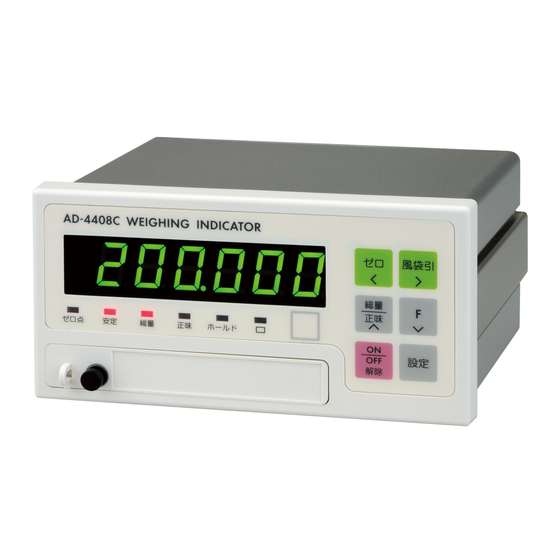
2. Introduction The AD-4408C is a weighing indicator that amplifies signals from a load cell, converts it to digital data and displays it as a mass value. The accessory panel mount packing will provide the indicator the IP-65 protection. This indicator has the following performance: Input sensitivity: ...... -
Page 7: Specifications
• Overflow display All the digits turn OFF. (When the polarity is negative, the minus sign appears at the highest-order digit.) Status indicators ZERO, STABLE, GROSS, NET, HOLD, Key switches ZERO, TARE, NET/GROSS, F, ON/OFF, ENTER, CAL Page 5 AD-4408C Weighing Indicator... -
Page 8: General
0.0 to 9.9 seconds (Can be set optionally within the range.) • Stability detection band 0 to 9 d (Can be set optionally within the range.) Digital filter Cutoff frequency range: 0.07 to 11 Hz Page 6 AD-4408C Weighing Indicator... - Page 9 Installation method Panel mount Mass Approximately 800 g 3.3.4. Accessories Item Quantity Model name CC-Link connector 1TM-721-105/037A Connector operation lever 1TM-231-131 Weighing capacity plate 108-4023453 Unit label 108-4023456 Panel mount packing 106-4004213 Terminal block cover 107-4005384 Page 7 AD-4408C Weighing Indicator...
-
Page 10: Description Of Each Part
Place a weighing capacity plate. • The key to enter the calibration mode. • The key is concealed by a sealable cover. 10 CAL To avoid unintentional operations, keep the cover attached except when entering the calibration mode. Page 8 AD-4408C Weighing Indicator... - Page 11 • The zero conditions are set in the calibration-related functions. ZERO • The key shifts the position of the blinking digit to the left when the numerical values are being entered. • Can be sealed using a wire seal. 17 Seal Page 9 AD-4408C Weighing Indicator...
-
Page 12: Rear Panel
AC power source AC power source NOTE: Terminals 7 (SHLD) and 11 (E) are internally connected. To avoid unintentional operations, keep the cover attached on the terminal block. Screw size: M3, tightening torque: 0.5N m Page 10 AD-4408C Weighing Indicator... - Page 13 3 CC-Link status LEDs Blinking • Resetting Normal • No signal Transmitting Receiving • Setting error When setting • CRC error Normal value is changed. • Station trouble Page 11 AD-4408C Weighing Indicator...
-
Page 14: Installation
It makes the front panel water-resistant equivalent to IP-65. Panel mount packing Guide rail Control panel Washer Screw Fig.3 Panel mounting method Page 12 AD-4408C Weighing Indicator... -
Page 15: Load Cell Cable Type
AD-4408C. No ground is connected between the load cell and the AD-4408C. This is to prevent the ground loop generated by multiple ground points. Gound loop can be a major cause of noise and interference. -
Page 16: Load Cell Connection
5.4. Load Cell Connection Two types of load cell connection are available: 6-wire connection and 4-wire connection. For high precision and stable weighing, 6-wire connection is recommended. (A) 6-wire connection (B) 4-wire connection Fig.4 Load cell connection Page 14 AD-4408C Weighing Indicator... -
Page 17: Checking The Load Cell Connection
When the load cell connection is complete, follow the procedure below to check the connection. Step 1 Perform a visual check to ensure that the wiring is correct. Step 2 Turn the AD-4408C ON. All the digits may be OFF before calibration. Even under such a condition, the check mode can be used. -
Page 18: Operation
A ZERO error is not output even if zero tracking is not performed. Functions related to zero tracking Calf06 : Changes the zero tracking time. (0.0 to 5.0 seconds) Calf07 : Changes the zero tracking band. (0.0 to 9.9 d) Page 16 AD-4408C Weighing Indicator... - Page 19 Press the switch once and release the switch to turn ON or OFF. Press the switch again to turn OFF or ON. Momentary switch Only when the switch is being pressed, the F key is ON. When released, OFF. Page 17 AD-4408C Weighing Indicator...
- Page 20 Data Method Description Calibration data EEPROM Maintained regardless of battery condition. Function data Zero value Battery The life of the battery is approximately 10 years Tare weight backup RAM at 25°C with the power disconnected. Page 18 AD-4408C Weighing Indicator...
-
Page 21: Mode Map
NOTE: When the power is Calibration Calibration-related disconnected with OFF mode function mode mode, the indicator Enter using the CAL key starts with OFF mode All data upon power-ON again. initialization mode Fig.5 Mode map Page 19 AD-4408C Weighing Indicator... -
Page 22: Calibration
Clears all the data in the EEPROM and battery backup All data initialization RAM. NOTE: All the data set in the calibration mode is stored in the EEPROM and is maintained regardless of battery condition. Page 20 AD-4408C Weighing Indicator... -
Page 23: Calibration With An Actual Load (Cal5Et)
Step 6 Place a calibration weight on the load cell. Wait for the stabilization indicator to turn ON and press the ENTER key. - - - - - - is displayed for approximately two seconds. Calend is displayed. To re-adjust the span, press the F key. Step 7 Page 21 AD-4408C Weighing Indicator... - Page 24 NOTE: If C errX is displayed, an error has occurred. Refer to “7.4. Calibration Errors” to take some measures. If the decimal point blinks, it indicates that the current value is not the weight value. Page 22 AD-4408C Weighing Indicator...
-
Page 25: Calibration-Related Functions (Calf)
NOTE: If a value exceeding the settable range is entered, err dt is displayed and the input is canceled. If the decimal point blinks, it indicates that the current value is not the weight value. Page 23 AD-4408C Weighing Indicator... - Page 26 For example, if this is set to 2, the value in the range of ±2% of the weighing capacity with the calibration zero point at the center will set to zero. Page 24 AD-4408C Weighing Indicator...
- Page 27 Performs zero tracking using this setting in combination with the setting of the zero Zero tracking time. Calf07 tracking 0. 0 When 0.0, zero tracking will not be 0. 0 9. 9 band performed. Unit: d (minimum division) in 0.1 increments Page 25 AD-4408C Weighing Indicator...
- Page 28 Tare when the gross weight is negative. Calf11 gross 0: Disables tare. weight 1: Enables tare. negative Output Standard serial output if the weight value when Calf12 overflows and is unstable. overflow 0: Disables output. 1: Enables output. unstable Page 26 AD-4408C Weighing Indicator...
- Page 29 Input voltage at span of weight value Calf19 Calf17 corresponding When performing digital span, 20000 999999 to Input are required. voltage at The decimal point position is the same as span Calf02 the setting of Page 27 AD-4408C Weighing Indicator...
- Page 30 ID numbers and outputting by Communication auto printing restriction 0: Disables restriction. 1: Enables restriction. Second header for serial output Calf22 Header 2 1: GS / NT / TR 2: G_ / N_ / T_ (_ space) Page 28 AD-4408C Weighing Indicator...
-
Page 31: Calibration Errors
Voltage at span calibration is less than Check load cell C err7 voltage at the zero point. connection. Page 29 AD-4408C Weighing Indicator... -
Page 32: Load Cell Output Adjustment
EXC- EXC- Fig.6 Load cell output adjustment NOTE: As the zero adjustment range of the AD-4408C is wide, output adjustment is rarely required for the normal load cell. Before adjusting the load cell output, check the load cell (deformation, clearance around the load cell, incorrect wiring and load cell type) and load cell connection. -
Page 33: General Functions
8. General Functions General functions are divided into groups per function and are indicated by the group name with the function number. NOTE: General functions determine the AD-4408C performance and all the data are stored in the EEPROM. 8.1. Setting Procedure Step 1 While holding down the ENTER key, press the F key. -
Page 34: Adjusting The Digital Filter
Cutoff frequency: 0.5 Hz to 0.1 Hz fncf05 cutoff frequency Digital filter cutoff frequency = fncf06 divider ratio High cutoff frequency Low cutoff frequency High response speed Low response speed ⇔ Prone to external disturbance Less prone to external disturbance Page 32 AD-4408C Weighing Indicator... -
Page 35: Basic Functions (Fncf)
5: 2.8 Hz 6: 2.0 Hz 7: 1.4 Hz 8: 1.0 Hz 9: 0.7 Hz Frequency fncf06 Divides digital filter cutoff frequency by the divider setting. ratio fncf07 1: Normal hold Hold 2: Peak hold Page 33 AD-4408C Weighing Indicator... -
Page 36: Standard Serial Output (Cl F)
1: 625 kbps CC f03 2: 2.5 Mbps Baud rate 5 Mbps 4: 10 Mbps 0: Not required (When the AD-4408C is turned on and the CC-Link is ready, the remote READY flag (RX007B) becomes active without performing initialization.) CC f04... -
Page 37: Interface
F.G. Fig.7 Standard serial output pin connection Fig.8 Standard serial output internal circuit NOTE: The standard serial output connection has no polarity. When a shielded cable is used, connect the shield to the F.G. terminal. Page 35 AD-4408C Weighing Indicator... - Page 38 A&D standard format examples Gross weight Net weight Tare weight Data with a decimal point Positive overflow Negative overflow Unstable data “Output OFF” data NOTE: The decimal point position is the same even when overflow occurs. Page 36 AD-4408C Weighing Indicator...
-
Page 39: Cc-Link
The AD-4408C CC-Link is a remote device station of CC-Link ver.1.10. When a CC-Link is used, the AD-4408C can be controlled by the PLC remote I/O or remote registers. So, the program can be simple. And connection to a PLC is simple, thus, a weighing system can be built easily. - Page 40 Status LEDs Blinking • Resetting Normal • No signal Transmitting Receiving • Setting error When the setting • CRC error Normal values are changed • Station trouble Fig.9 CC-Link connector and LEDs Page 38 AD-4408C Weighing Indicator...
- Page 41 9.2.1. Address map Remote register (Number of occupied stations: 4) Addresses are examples when the station number is set to 1. AD-4408C --> Master station Master station --> AD-4408C Remote Buffer Remote Buffer Station Name Name register memory register memory...
- Page 42 Error code Error code Error status flag (Indicator error) No error AD error (Module error) EEPROM error (Writing error) RAM error (Writing error) Calibration error (Calibration value error) Display error (Mode error) Page 40 AD-4408C Weighing Indicator...
- Page 43 Remote I/O (Number of occupied stations: 4) Addresses are examples when the station number is set to 1. AD-4408C --> Master station Master station --> AD-4408C Remote Buffer Remote Buffer Station Name Name input memory output memory RX0000 Reserved RY0000...
- Page 44 AD-4408C --> Master station Master station --> AD-4408C Remote Buffer Remote Buffer Station Name Name input memory output memory RX0060 Net over RY0060 RX0061 Net under RY0061 RX0062 Gross over RY0062 RX0063 Gross under RY0063 RX0064 A/D over RY0064 RX0065...
- Page 45 Remote I/O (Number of occupied stations: 2) Addresses are examples when the station number is set to 1. AD-4408C --> Master station Master station --> AD-4408C Remote Buffer Remote Buffer Station Name Name input memory output memory RX0000 Reserved RY0000...
- Page 46 AD-4408C --> Master station Master station --> AD-4408C Remote Buffer Remote Buffer Station Name Name input memory output memory RX0020 Net over RY0020 RX0021 Net under RY0021 RX0022 Gross over RY0022 RX0023 Gross under RY0023 RX0024 A/D over RY0024 RX0025...
- Page 47 Remote I/O (Number of occupied stations: 1) Addresses are examples when the station number is set to 1. AD-4408C --> Master station Master station --> AD-4408C Remote Buffer Remote Buffer Station Name Name input memory output memory RX0000 RY0000 Zero...
- Page 48 9.2.2. Commands The write command is used to send a command to the AD-4408C from the master station. For details, refer to “Write command” in “9.2.3. Timing chart”. Command No. Command data Command Zero Clear zero Tare Clear tare Hold...
- Page 49 Resuming from suspended modes When the AD-4408C is in a mode that suspends weighing, such as calibration or OFF mode, the remote READY flag (RX007B) becomes inactive because a correct weight value can not be output. To resume from this condition, take the same steps as described in “When the AD-4408C is turned on”...
- Page 50 Fig.12 Performance of the write command CPU normal operation The CPU normal operation (RX0006) is a signal to check that the AD-4408C is turned on and it functions normally. During normal operation, the signal is reversed at an interval of 0.5 to 1 second.
- Page 51 Error status flag When an error occurs to the AD-4408C, the remote READY flag (RX007B) becomes inactive and the error status flag (RX007A) becomes active to inform the master station of the error occurrence. The master station requests to reset the error status flag, by activating the request flag of error reset (RY007A).
-
Page 52: Maintenance
Step 3 Press the ∧ or ∨ key to select the item to be checked and press the ENTER key to enter the check mode of the selected item. To exit from the current mode, press the ESC key. Page 50 AD-4408C Weighing Indicator... - Page 53 0 . 0 C R L F Test data S T , G S , + 0 0 0 0 0 . 0 k g Page 51 AD-4408C Weighing Indicator...
- Page 54 With Chc in displayed, press the ENTER key to enter the internal count check mode. The internal count value (display value times 10) is displayed. The example below is when the internal count is 123. 1 2 3 . Page 52 AD-4408C Weighing Indicator...
- Page 55 The example below is when the checksum is EF. 10.2.12. Checking the calibration-related functions About the settings of the calibration-related functions, refer to “7.3. Calibration-Related Functions”. Page 53 AD-4408C Weighing Indicator...
-
Page 56: Initialization Mode
ENTER key for three seconds or more. After initialization, the indicator is reset and all the display segments are ON. And the indicator enters the weighing mode. To exit from this mode without performing initialization, press the ESC key. Page 54 AD-4408C Weighing Indicator... - Page 57 ENTER key for three seconds or more. After initialization, the indicator is reset and all the display segments are ON. And the indicator enters the weighing mode. To exit from this mode without performing initialization, press the ESC key. Page 55 AD-4408C Weighing Indicator...
-
Page 58: Checking The Load Cell Connection Using The Digital Multimeter
About 2.5V (half of the excitation voltage) voltage Compared with the theoretical value obtained from the load cell rating, actual SIG+ SIG- Load cell output load and excitation voltage. voltage Normally 0 to 15mV. Page 56 AD-4408C Weighing Indicator... - Page 59 If the AD-4408C does not function properly, contact the nearest A&D dealer. Use the chart below to write necessary items before contacting the dealer. Item Record your value Description For 4-wire connection, a jumper is □ 4-wire connection required between...
-
Page 60: Setting List
2: 8.0 Hz 3: 5.6 Hz fncf05 4: 4.0 Hz 5: 2.8 Hz 6: 2.0 Hz 7: 1.4 Hz 8: 1.0 Hz 9: 0.7 Hz fncf06 Frequency divider ratio Hold fncf07 1: Normal hold 2: Peak hold Page 58 AD-4408C Weighing Indicator... -
Page 61: Standard Serial Output
0: 156 kbps CC f03 1: 625 kbps 2: 2.5 Mbps 5 Mbps 4: 10 Mbps Initialization CC f04 0: Not required 1: Required Output data CC f05 0: Displayed weight 1: Net weight 2: Gross weight Page 59 AD-4408C Weighing Indicator... -
Page 62: Calibration-Related Functions
1: Enables both functions. Tare when the gross weight is negative. Calf11 0: Disables tare. 1: Enables tare. Standard serial output if the weight value Calf12 overflows and is unstable. 0: Disables output. 1: Enables output. Page 60 AD-4408C Weighing Indicator... - Page 63 Select whether or not to restrict Calf21 network-related communication. 0: Disables restriction. 1: Enables restriction. Second header for serial output Calf22 1: GS / NT / TR 2: G_ / N_ / T_ (_ space) Page 61 AD-4408C Weighing Indicator...
-
Page 64: External Dimensions
12. External Dimensions Unit: mm Fig.16 External dimensions Page 62 AD-4408C Weighing Indicator... - Page 65 MEMO Page 63 AD-4408C Weighing Indicator...
- Page 66 MEMO Page 64 AD-4408C Weighing Indicator...
- Page 68 3-23-14 Higashi-Ikebukuro, Toshima-ku, Tokyo 170-0013 JAPAN Telephone: [81] (3) 5391-6132 Fax: [81] (3) 5391-6148 A&D ENGINEERING, INC. 1756 Automation Parkway, San Jose, California 95131 U.S.A. Telephone: [1] (408) 263-5333 Fax: [1] (408)263-0119 A&D INSTRUMENTS LIMITED <UK Office> Unit 24/26 Blacklands Way, Abingdon Business Park, Abingdon, Oxfordshire OX14 1DY United Kingdom Telephone: [44] (1235) 550420 Fax: [44] (1235) 550485...
Need help?
Do you have a question about the AD-4408C and is the answer not in the manual?
Questions and answers