Table of Contents
Advertisement
Quick Links
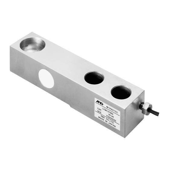
ビーム型ステンレスロードセル
LCM13シリーズ
LCM13K100/LCM13K200/LCM13K300/LCM13K500
LCM13T001/LCM13T002/LCM13T003/LCM13T005
本社 〒170-0013 東京都豊島区東池袋3-23-14
(ダイハツ・ニッセイ池袋ビル5F)
TEL03-5391-6126(代) FAX03-5391-6129
1. 概要
LCM13シリーズは、フロアスケールに最適なビーム型ロードセルです。
ステンレス製で、耐環境性を要求される場所での使用に適しています。
また、設置方法が容易なため、シンプルな計量機器を製作できます。
2. 仕様
定格容量 ............. 1kN、2kN、3kN、5kN、10kN、20kN、30kN、50kN
定格出力 ............. 2.0mV/V±0.1%
最大許容過負荷 ....... 150% OF R.O.
総合誤差 ............. 0.03% OF R.O.
ゼロバランス ......... ±1% OF R.O.
温度補償範囲 ......... -10℃~40℃
推奨印加電圧 ......... 5 V ~ 12 V
最大印加電圧 ......... 15 V
入力端子間抵抗 ....... 380Ω±20Ω
出力端子間抵抗 ....... 350Ω±3.5Ω
絶縁抵抗 ............. 5000MΩ以上/DC50V
ゼロ点の温度影響 ..... 0.016% OF R.O./10℃
出力の温度影響 ....... 0.013% OF LOAD/10℃
ケーブル太さ、長さ .... φ4×3m
質量 (自重)
LCM13K100、LCM13K200、LCM13K300、LCM13K500、LCM13T001......... 1 kg
LCM13T002、LCM13T003 ....................................... 1.5 kg
LCM13T005 .................................................... 2 kg
3. 設置にあたっての注意点
3.1. ロードセルの設置
1 ロードセルを固定する部分の強度は十分強固なものにしてください。 この
部分が簡単に傾いたり、曲がったりすると精度に悪影響を及ぼします。
2 ロードセル取付面は表面粗さ100S(三角記号で
さい。
3 ロードセルの取付けには、強度区分10.9相当以上の六角穴付ボルト又
は、ハイテンション六角ボルトを使用してください。一般的な市販ボル
ト(低引張強度)は強度が不足しますので、使用しないでください。ボル
トの推奨締め付けトルクは次表の通りです。
LCM13K100、 LCM13K200、
LCM13K300、 LCM13K500、 LCM13T001
LCM13T002、 LCM13T003、 LCM13T005
4 ロードセルを取付ける前に、 取付面に付着しているゴミ等を必ず取り除いて
ください。 ボルトを締め付ける時は、 ロードセルに横荷重やねじりが加わら
ないように注意してください。
3.2. ロードセルへの負荷
ロードセルへの負荷の方法は、必要とされる計量精度、計量機器の構造
により様々な方法が考えられます。以下に例を示しますので、参考にし
てください。
1 ロードセルに直接計量台の脚(アジャスタブルパッド)を取付ける。
構造はシンプルであるが計量精度はそれほど期待できない。
アジャスタブルパッドはパッドの部分
が自在に動くものを選択する。
ロードセル
脚(アジャスタブルパッド)
WM+PD4000731D
)以上に仕上げてくだ
ボルト径
推奨締め付けトルク
M12
80N・m
M20
400N・m
計量台
STAINLESS STEEL BEAM LOAD CELL
LCM13 Series
LCM13K100/LCM13K200/LCM13K300/LCM13K500
LCM13T001/LCM13T002/LCM13T003/LCM13T005
3-23-14 Higashi-Ikebukuro, Toshima-ku, Tokyo
170-0013 JAPAN
Tel: [81](3)5391-6132 Fax: [81](3)5391-6148
1. INTRODUCTION
The LCM13 series, are stainless steel beam load cells, are ideally suited for
platform scale and use in harsh environment and are designed for the simple
installation. Therefore, it is possible to design a simple weighing instrument.
2. SPECIFICATIONS
Rated capacities............. 1 kN, 2 kN, 3 kN, 5 kN, 10 kN, 20 kN, 30 kN, 50 kN
Rated output ..............................................................................2.0mV/V±0.1%
Maximum safe overload............................................................ 150% OF R.O.
Combined error.........................................................................0.03% OF R.O.
Zero balance................................................................................ ±1% OF R.O.
Compensated temperature range ..............................................-10°C to 40°C
Recommended excitation voltage .................................................. 5 V to 12 V
Maximum excitation voltage.......................................................................15 V
Input terminal resistance ................................................................. 380Ω±20Ω
Output terminal resistance ............................................................. 350Ω±3.5Ω
Insulation resistance..................................... Greater then 5000MΩ at DC50V
Temperature effect on zero...........................................0.016% OF R.O./10°C
Temperature effect on span....................................... 0.013% OF LOAD/10°C
Diameter and length of cable ............................................................... φ4×3m
Mass of load cell
LCM13K100, LCM13K200, LCM13K300, LCM13K500, LCM13T001......1 kg
LCM13T002, LCM13T003 ..........................................................................1.5 kg
LCM13T005.....................................................................................................2 kg
3. NOTE ON INSTALLATION
3.1. ATTACHING THE LOAD CELL
1 Attach the load cell to a rigid and flat base. If there is slope or distortion
on a part of the base, it affects the measurement accuracy.
2 Prepare the mounting surface so that the surface roughness is within
100μm in maximum.
3 Use high tensile bolts or hexagonal bolts that have strength
classification 10.9 (tensile grade: 1000MPa, yield grade: 900MPa).
If a low tensile bolt is used, it will be damaged because of weak tensile
strength. Recommended torque is as follows:
LCM13K100, LCM13K200,
LCM13K300, LCM13K500,
LCM13T001
LCM13T002, LCM13T003,
LCM13T005
4 Clean the mounting surface before attaching the load cell.
Avoid torsional force or stress without specified direction when
tightening the load cell mounting bolts.
3.2. LOADING TO THE LOAD CELL
There are many loading methods, depending on the required accuracy
and the weighing instrument. Refer to the following examples of
applying loading to the load cell.
1 Attaching the foot to the load cell directly.
This structure is simple, but scale is a low precision.
Use a leveling foot that the height
can be adjusted.
Load cell
Leveling foot
Bolt diameter
Recommended torque
M12
80 N•m
M20
400 N•m
Platform
Advertisement
Table of Contents

Subscribe to Our Youtube Channel
Related Manuals for A&D LCM13K100


Summary of Contents for A&D LCM13K100
-
Page 1: Specifications
Diameter and length of cable ............... φ4×3m ケーブル太さ、長さ ..φ4×3m 質量 (自重) Mass of load cell LCM13K100、LCM13K200、LCM13K300、LCM13K500、LCM13T001..1 kg LCM13K100, LCM13K200, LCM13K300, LCM13K500, LCM13T001..1 kg LCM13T002、LCM13T003 ........1.5 kg LCM13T002, LCM13T003 ................1.5 kg LCM13T005 ............ 2 kg LCM13T005.....................2 kg 3. 設置にあたっての注意点... - Page 2 LCM13T003 Unit: mm LCM13T005 20.5 単位:mm F 36 F 36 力方向 力方向 Force direction Force direction Fixed surface 2 Fixed surface 2 固定面 固定面 LCM13K500, LCM13T001, LCM13K100, LCM13K200, LCM13K100、 LCM13K200、 LCM13K500、 LCM13T001、 LCM13T002, LCM13T003, LCM13K300 LCM13K300 LCM13T002、 LCM13T003、 LCM13T005 LCM13T005...
Need help?
Do you have a question about the LCM13K100 and is the answer not in the manual?
Questions and answers