Table of Contents
Advertisement
Save these instructions for future use!
FAILURE TO READ AND FOLLOW ALL INSTRUCTIONS
CAREFULLY BEFORE INSTALLING OR OPERATING THIS
CONTROL COULD CAUSE PERSONAL INJURY AND/OR
PROPERTY DAMAGE.
APPLICATIONS
THERMOSTAT APPLICATION GUIDE
Confi guration Options
Gas, Oil, Electric, Heat Only,
Cool Only or Heat/Cool
Systems, 2 or 3 wire Hydronic
Zone (Hot Water or Steam)
Systems, 24 Volt or Millivolt
Single Stage Compressor
Heat Pump Systems - up to 2
Stages Aux./Emergency Heat
Heat Pump 2
Two Stage or Two Compressor
Two Stage or Two
Heat Pump systems - up to 2
Compressor Heat Pump
Stages Aux./Emergency Heat
(HP2)
SPECIFICATIONS
Electrical Rating:
Battery Power . . . . . . . . . . . . . . . . . . . . . . . . . . mV to 30 VAC, NEC Class II, 50/60 Hz or DC
Input-Hardwire . . . . . . . . . . . . . . . . . . . . . . . . . 20 to 30 VAC
Terminal Load . . . . . . . . . . . . . . . . . . . . . . . . . . . . . 1.5A per terminal, 2.5A maximum all terminals combined
Setpoint Range . . . . . . . . . . . . . . . . . . . . . . . . . . . . 45 to 99°F (7 to 32°C)
Differential (Single Stage) . . . . . . . . . . . . . . . . . . . . Heat 0.6°F; Cool 1.2°F
Differential (Multi-Stage) . . . . . . . . . . . . . . . . . . . . . Heat 0.6°F; Cool 1.2°F
Differential (Heat Pump) . . . . . . . . . . . . . . . . . . . . . Heat 1.2°F; Cool 1.2°F
Operating Ambient. . . . . . . . . . . . . . . . . . . . . . . . . . 32°F to +105°F (0 to +41°C)
Operating Humidity . . . . . . . . . . . . . . . . . . . . . . . . . 90% non-condensing max.
Shipping Temperature Range . . . . . . . . . . . . . . . . . -40 to +150°F (-40 to +65°C)
Dimensions Thermostat. . . . . . . . . . . . . . . . . . . . . . 4.2"H x 6.4"W x 1.7"D
CAUTION
!
To prevent electrical shock and/or equipment damage,
disconnect electric power to system at main fuse or
circuit breaker box until installation is complete.
Index
Installation
Wiring Connections
Maximum
Thermostat
Stages
Heat/Cool
1/1
2/2
3/1
4/2
Page
2
2
3
4
5
7
8
www.white-rodgers.com
Blue Easy Reader Thermostat
Single Stage, Multi-Stage, Heat Pump
Installation and Operating Instructions for Model:
Model
Programming Choices
1F95EZ-0671
Non-Programmable
1F95EZ-0671 Thermostat
ATTENTION: MERCURY NOTICE
This product does not contain mercury. However, this
product may replace a product that contains mercury.
Mercury and products containing mercury must not be
discarded in household trash. Do not touch any spilled
mercury. Wearing non-absorbent gloves, clean up any
spilled mercury and place in a sealed container. For
proper disposal of a product containing mercury or a
sealed container of spilled mercury, place it in a suitable
shipping container. Refer to www.white-rodgers.com for
location to send product containing mercury.
7 Day
PART NO. 37-6986A
0846
Advertisement
Table of Contents

Related Manuals for White Rodgers 1F95EZ-0671


Summary of Contents for White Rodgers 1F95EZ-0671
-
Page 1: Table Of Contents
FAILURE TO READ AND FOLLOW ALL INSTRUCTIONS CAREFULLY BEFORE INSTALLING OR OPERATING THIS 1F95EZ-0671 Non-Programmable 7 Day CONTROL COULD CAUSE PERSONAL INJURY AND/OR PROPERTY DAMAGE. APPLICATIONS THERMOSTAT APPLICATION GUIDE 1F95EZ-0671 Thermostat Maximum Thermostat Thermostat Stages Confi guration Options Applications Heat/Cool Gas, Oil, Electric, Heat Only,... -
Page 2: Thermostat
6. Push excess wire into wall and plug hole with a fi re re- corrects the condition. sistant material (such as fi berglass insulation) to prevent Figure 1 – Thermostat Base Multi-Stage 1F95EZ-0671 drafts from affecting thermostat operation. 7. Carefully line the thermostat up with the base and snap into place. -
Page 3: Applications
WIRING DIAGRAMS Single Stage, Multi-Stage and Heat Figure 2 – Single Stage or Multi-Stage System (No Heat Pump) Pump Connections with Single Transformer Refer to equipment manufacturers' instructions for specifi c system wiring information. Jumper This thermostat is designed to operate a single-transformer or two-transformer system. -
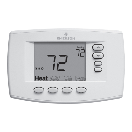
Page 4: Thermostat Quick Reference
THERMOSTAT QUICK REFERENCE Home Screen Description Figure 6 – Home Screen Display Room Setting Temperature Temperature Battery Level Indicator Indicating the current power level of the 2 “AA” batteries. Full power remaining. Half power remaining. Change The batteries should be replaced at this time with 2 new premium brand “AA”... -
Page 5: Installer Confi Guration Menu
INSTALLER/CONFIGURATION MENU With Heat or A/C selected, press and hold the Menu button for at least 5 seconds. The display will show item #1 in the table below. Press Menu to advance to the next menu item. Press to change a menu item options. INSTALLER/CONFIGURATION MENU Menu HP SS... - Page 6 INSTALLER/CONFIGURATION MENU 1) This control can be confi gured for: terminal is not powered, the light will be on momen- tarily after any button is pressed no matter whether the backlight MS 2 – Multi-Stage System (no heat pump) is selected ON or OFF. HP 1 –...
-
Page 7: Operating Your Thermostat
OPERATING YOUR THERMOSTAT Check Thermostat Operation CAUTION NOTE To prevent compressor and/or property damage, if the outdoor temperature is below 50°F, DO NOT operate To prevent static discharge problems, touch side of the cooling system. thermostat to release static build-up before touching any keys. -
Page 8: Troubleshooting
TROUBLESHOOTING Reset Operation Note: When thermostat is reset, installer confi guration menu settings and programming will reset to factory settings. If a voltage spike or static discharge blanks out the display or causes erratic thermostat operation, you can reset the thermo- stat by removing the wires from terminals RH and RC (do not short them together) and removing batteries for 2 minutes.
Need help?
Do you have a question about the 1F95EZ-0671 and is the answer not in the manual?
Questions and answers