White Rodgers 1F95-1277 Installation And Operating Instructions Manual
Big blue universal thermostat with automatic heat/cool changeover option
Hide thumbs
Also See for 1F95-1277:
- Installation and operating instructions manual (12 pages) ,
- Installation and operating instructions manual (13 pages)
Advertisement
Save these instructions for future use!
FAILURE TO READ AND FOLLOW ALL INSTRUCTIONS
CAREFULLY BEFORE INSTALLING OR OPERATING THIS
CONTROL COULD CAUSE PERSONAL INJURY AND/OR
PROPERTY DAMAGE.
APPLICATIONS
THERMOSTAT APPLICATION GUIDE
Description
Heat Pump (No Aux . or Emergency Heat)
Heat Pump (with Aux . or Emergency Heat)
Systems with up to 3 Stages Heat, 2 Stages Cool
Heat Only Systems
Millivolt Heat Only Systems - Floor or Wall Furnaces
Cool Only Systems
Gas or Oil Heat
Electric Furnace
Hydronic (Hot Water) Zone Heat - 2 Wires
Hydronic (Hot Water) Zone Heat - 3 Wires
Wired Remote Temperature Sensor (Indoor/Outdoor)
Dual Fuel Feature (Heat Pump Mode)
SPECIFICATIONS
Electrical Rating:
Battery Power . . . . . . . . . . . . . . . . . . . . . . . . . . mV to 30 VAC, NEC Class II, 50/60 Hz or DC
Input-Hardwire . . . . . . . . . . . . . . . . . . . . . . . . . 20 to 30 VAC
Terminal Load . . . . . . . . . . . . . . . . . . . . . . . . . . . . . 1 .5A per terminal, 2 .5A maximum all terminals combined
Setpoint Range . . . . . . . . . . . . . . . . . . . . . . . . . . . . 45 to 99°F (7 to 37°C)
Differential (Single Stage) . . . . . . . . . . . . . . . . . . . . Heat 0 .6°F; Cool 1 .2°F
Differential (Multi-Stage) . . . . . . . . . . . . . . . . . . . . . Heat 0 .6°F; Cool 1 .2°F
Differential (Heat Pump) . . . . . . . . . . . . . . . . . . . . . Heat 1 .2°F; Cool 1 .5°F
Operating Ambient . . . . . . . . . . . . . . . . . . . . . . . . . . 32°F to +105°F (0 to +41°C)
Operating Humidity . . . . . . . . . . . . . . . . . . . . . . . . . 90% non-condensing max .
Shipping Temperature Range . . . . . . . . . . . . . . . . . -4 to +150°F (-20 to +65°C)
Dimensions Thermostat . . . . . . . . . . . . . . . . . . . . . . 4-9/16"H x 5-13/16"W x 1-3/16"D
CAUTION
!
To prevent electrical shock and/or equipment damage,
disconnect electric power to system at main fuse or
circuit breaker box until installation is complete.
Index
Big Blue Universal Thermostat with
Automatic Heat/Cool Changeover Option
Single Stage, Multi-Stage, Heat Pump
Installation and Operating Instructions for Model:
Model
1F95-1277
1F95-1277 Touchscreen Thermostat
Yes
Yes
Yes
Yes
Yes
Yes
Yes
Yes
Yes
Yes
Yes
Yes
ATTENTION: MERCURY NOTICE
This product does not contain mercury . However, this
product may replace a product that contains mercury .
Mercury and products containing mercury must not be
discarded in household trash . Do not touch any spilled
mercury . Wearing non-absorbent gloves, clean up any
Page
spilled mercury and place in a sealed container . For proper
2
disposal of a product containing mercury or a sealed
2
container of spilled mercury, place it in a suitable shipping
3
container . Refer to www.thermostat-recycle.org for
4
location to send the product containing mercury .
7
7
11
www.white-rodgers.com
www.emersonclimate.com
Programming Choices
Non-Programmable 5/1/1 Day
PART NO. 37-6753D
Replaces 37-6753C
7 Day
1150
Advertisement
Table of Contents

Related Manuals for White Rodgers 1F95-1277


Summary of Contents for White Rodgers 1F95-1277
-
Page 1: Table Of Contents
CONTROL COULD CAUSE PERSONAL INJURY AND/OR PROPERTY DAMAGE. APPLICATIONS THERMOSTAT APPLICATION GUIDE 1F95-1277 Touchscreen Thermostat Description Heat Pump (No Aux . or Emergency Heat) Heat Pump (with Aux . or Emergency Heat) Systems with up to 3 Stages Heat, 2 Stages Cool Heat Only Systems Millivolt Heat Only Systems –... -
Page 2: Installation
Energizer ® 1 . The cover, which may be either a snap-on or hinge type . Figure 1 – Thermostat Base Multi-Stage 1F95-1277 2 . The base, which is removed by loosening all captive screws . 3 . The switching subbase, which is removed by unscrewing the mounting screws that hold it on the wall or adapter plate . -
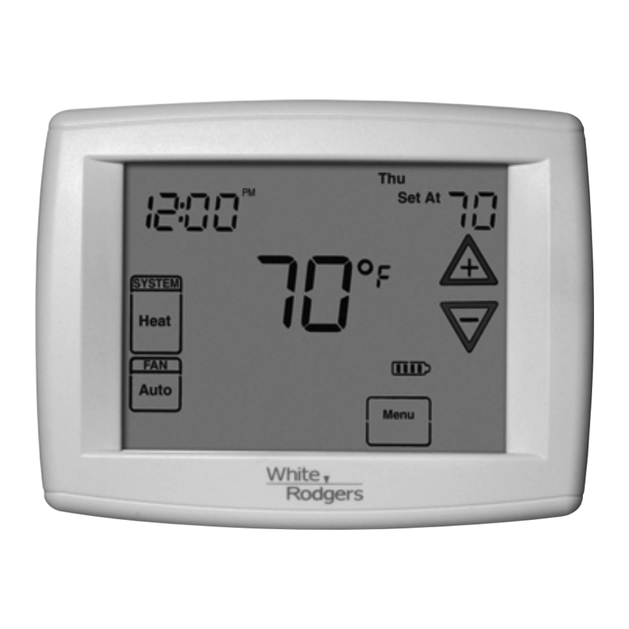
Page 3: Thermostat Quick Reference
THERMOSTAT QUICK REFERENCE Home Screen Description Figure 2 – Home Screen Display Room Temperature Day of Week Set Temperature Time of Day Temperature UP/Down used for System modifying set point Switch as well as to navigating the menus Enters comfort Switch temperature settings into the schedule... -
Page 4: Installer Configuration Menu
INSTALLER/CONFIGURATION MENU To enter the menu: Press the Menu touch key . Press and hold for 5 seconds the Installer Config touch key . This displays menu item #1 in the table below . Press to advance to the next menu item or to return to a previous menu item . - Page 5 INSTALLER/CONFIGURATION MENU 1) This control can be configured for: the thermostat compressor time delay is activated, it will MS2 – Multi-Stage System (2 heat/2 cool) flash the set point for up to five minutes. HP1 – Heat Pump with one stage of compressor 11) Select Continuous Backlight –...
- Page 6 INSTALLER/CONFIGURATION MENU 23 & 24) Select Fast Second Stage ON or OFF – In the run 20) Heat Temperature Limit Range – This feature adjusts mode, with the fast Heat feature enabled (FA Heat On), if the highest setpoint temperature for heat . The default the Heat setpoint temperature is manually raised by 3°F setting is 99°F .
-
Page 7: Operating Your Thermostat
OPERATING YOUR THERMOSTAT IMPORTANT! Choose the Fan Setting (Auto or On) Manual Operation (Bypassing the Program) Programmable Mode Fan Auto is the most commonly selected setting and runs the fan only when the heating or cooling system is on . Press and the HOLD button and adjust the tempera- Fan On selection runs the fan continuously for increased air... -
Page 8: Enter The Cooling Program
PROGRAMMING Programming Tip: Copy Program Enter the Cooling Program When programming your thermostat, you may copy the pro- 1) Press the SYSTEM button until the Cool icon appears . 2) Follow Enter Heating Program instructions for entering gram from one day to another day or group of days using the Copy key . - Page 9 Energy Saving Factory Pre-Program The 1F95-1277 thermostats are programmed with the energy saving settings shown in the table below for all days of the week . If this program suits your needs, simply set the thermostat clock and press the RUN button .
-
Page 10: Wired Remote Temperature Sensing
PROGRAMMING Wired Remote Temperature Sensing Example: Local sensor temperature is 80° and the remote sensor is 70° . One remote temperature sensor can be installed indoor or If weight is selected H4, the averaged temperature of 72° will outdoor and connected to the thermostat by a maximum be displayed . -
Page 11: Troubleshooting
TROUBLESHOOTING Reset Operation Note: When thermostat is reset, installer configuration menu settings and programming will reset to factory settings. If a voltage spike or static discharge blanks out the display or causes erratic thermostat operation, you can reset the thermostat by removing the wires from terminals R and C (do not short them together) and removing batteries for 2 minutes . - Page 12 HOmeOwNeR HelP liNe: 1-800-284-2925 White-Rodgers is a business of Emerson Electric Co. The Emerson logo is a www.white-rodgers.com trademark and service mark www.emersonclimate.com of Emerson Electric Co.
Need help?
Do you have a question about the 1F95-1277 and is the answer not in the manual?
Questions and answers