Advertisement
Quick Links
T E C H N O L O G I E S
User Guide
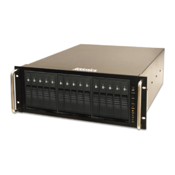
RAID Rack
(RR2035ASDML)
www.addonics.com
v8.1.11
Technical Support
If you need any assistance to get your unit functioning properly, please have your
product information ready and contact Addonics Technical Support at:
Hours: 8:30 am - 6:00 pm PST
Phone: 408-453-6212
Email: http://www.addonics.com/support/query/
Advertisement

Related Manuals for Addonics Technologies RR2035ASDML


Summary of Contents for Addonics Technologies RR2035ASDML
- Page 1 T E C H N O L O G I E S User Guide RAID Rack (RR2035ASDML) www.addonics.com v8.1.11 Technical Support If you need any assistance to get your unit functioning properly, please have your product information ready and contact Addonics Technical Support at:...
-
Page 2: Power Switch
Array 1 Array 3 Array 2 Front Power Switch System Reset Buzzer Reset LED Display Back Array 4 Fans Power Supply Multilane Connector www.addonics.com Technical Support (M-F 8:30am - 6:00pm PST) Phone: 408-453-6212 Email: www.addonics.com/support/query/... - Page 3 Power Switch: This is the switch to power devices connected to the power supply. The power LED will light up to indicate power is supplied. Note: The main power switch located at the back of enclosure must be turned on first. Reset Button: Not operational.
- Page 4 Installing drives into the RAID Rack 1. Be sure the lock on each drive door is in an unlock position. If not, use the key that comes with the Disk Array to unlock the drive door. Pull on the door lever to swing open the drive door all the way.
-
Page 5: How To Remove The Top Cover
Top Cover Screws How to Remove the Top Cover: Locate the 2 screws at the back of the storage rack Turn screws counterclockwise to loosen. Lift the top cover and pull towards the rear end of the rack. To Mount Back the Top Cover: Align the top cover with the edges of the rack. - Page 6 Thermal Management Card on the RAID Rack* Fan Connectors Overheat Buzzer Floppy Power Connector Ambient Detect Terminal Temp. Setting (40°C, 50°C, 60°C) Fan, Temperature and Power LED Connectors Fan Detect Selection Fan1 to Fan8 could be set either “ENABLE” or “DISABLE”. When all the fans are set on “DISABLE”, the Fan LED will have no light on.
- Page 7 Resetting the RAID Mode NOTE: This procedure destroys all RAID data. It should not harm individual drives or their contents; however, creating or running backups of all data is strongly recommended before proceeding. 1. Power down the unit and set the dip switch to the factory default setting (all switches OFF).
- Page 8 BZS Switch (SW1:1): The BZ switch is used to silence the audible alarm buzzer. The OFF position permits the audible alarm, and the ON position silences the audible alarm. The BZ switch has immediate effect. EZ Switch (SW1:2): The EZ (spare) switch inhibits spares when ON. When in the OFF position, all individual drives (not defined as members of an array) are considered spare.
- Page 9 JBOD Mode (Individual Drives) Number of drives: at least 1 Unit capacity: N/A (100% of each individual drive) Spares: no Fault tolerance: none JBOD mode offers all connected units to the host adapter, no RAID is defined at all. NOTE: JBOD mode requires a SATA controller featuring Port Multiplier support for eSATA connections.
- Page 10 RAID 3 (Stripe set with dedicated parity) Number of drives: at least 3 Unit capacity: size of one member times number of members minus one. Spares: yes Fault tolerance: can withstand the loss of one drive without losing data. RAID 3 works by striping data for individual I/O blocks across all members except one, which contains parity data for the stripe set computed by the Port Multiplier.
- Page 11 Notes about Spare Drives If EZ mode is disabled (SW1:2 ON), all individual drives not configured as array members will be offered to the host adapter as separate units. To create an array with one or more spares, set or modify the RAID mode using fewer than 5 members, while the spares are disconnected from the Port Multiplier.
- Page 12 CONTACT US www.addonics.com Phone: 408-573-8580 Fax: 408-573-8588 Email: http://www.addonics.com/sales/query/...
Need help?
Do you have a question about the RR2035ASDML and is the answer not in the manual?
Questions and answers