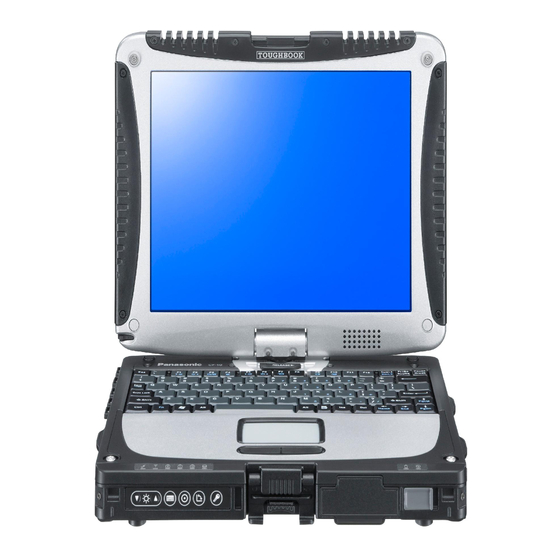
Panasonic Toughbook CF-19CHBAXBM Service Manual
Notebook computer
Hide thumbs
Also See for Toughbook CF-19CHBAXBM:
- Operating instructions manual (41 pages) ,
- Brochure & specs (2 pages) ,
- Brochure & specs (2 pages)
Table of Contents
Advertisement
Model No. CF-19CHBAX 1 2
1: Operation System
B: Microsoft® Windows® XP Professional
2: Area
M: Refer to above area table
CF-19CHBAXBM
Model No.
© 2006 Matsushita Electric Industrial Co., Ltd. All rights reserved.
Unauthorized copying and distribution is a violation of law.
ORDER NO.
Notebook Computer
This is the Service Manual for
the following areas.
M ...for U.S.A. and Canada
CPD0611206C1
Advertisement
Table of Contents

Related Manuals for Panasonic Toughbook CF-19CHBAXBM


Summary of Contents for Panasonic Toughbook CF-19CHBAXBM
-
Page 1: Notebook Computer
ORDER NO. CPD0611206C1 Notebook Computer CF-19CHBAXBM Model No. This is the Service Manual for the following areas. M …for U.S.A. and Canada Model No. CF-19CHBAX 1 2 1: Operation System B: Microsoft® Windows® XP Professional 2: Area M: Refer to above area table ©... - Page 5 10-1 11-1...
-
Page 6: Specifications
1 Specifications Main Specifications Model No. CF-19CHBAXBM CF-19CDBAXVM ® Intel Core™ Duo Processor U2400 (1.06 L2 cache, 533 FSB) ® Chipset Intel 945GM *1*2 Memory (4096 Max.) *1*3 Video Memory UMA (128 Max.) Hard Disk Drive Display Method 10.4 XGA type (TFT) Internal LCD 65,536/16,777,216 colors (800 ×... - Page 7 When using ExpressCard/34, the card slot cover cannot be closed. Operation has been tested and conÞ rmed using Panasonic SD Memory Cards with a capacity of up to 2 The transfer rate using the SD Memory Card slot on this computer is 8 per second.
-
Page 8: Names And Functions Of Parts
2 Names and Functions of Parts A: Wireless LAN Antenna G: LCD <Only for model with wireless LAN> <Only for model with touchscreen> Reference Manual “Wireless LAN” Reference Manual “Touchscreen” B: Bluetooth Antenna <Only for model with digitizer> <Only for model with Bluetooth> Reference Manual “Digitizer”... - Page 9 Left side Rear side Bottom A: DC-IN Jack L: Microphone Jack B: USB Port A condenser microphone can be used. If other types of microphones are used, audio input may not be pos- Reference Manual “USB Devices” sible, or malfunctions may occur as a result. C: IEEE 1394 Interface Connector When recording in stereo using a stereo micro- Reference Manual “IEEE 1394 Devices”...
- Page 10 3 Block Diagram...
-
Page 11: Diagnosis Procedure
4 Diagnosis Procedure 4.1. Basic Procedures... - Page 12 4.2. Troubleshooting Flow Chart...
- Page 13 5 Power-On Self Test (Boot Check)
- Page 14 6 List of Error Codes <Only when the port replicator is connected> nnnn nnnn nnnn nnnn nnnn nnnn...
- Page 15 device device device device nnnn nnnn nnnn nnnn...
- Page 16 7 Self Diagnosis Test...
- Page 19 7.1. Test Item and Division of trouble...
-
Page 21: Wiring Connection Diagram
8 Wiring Connection Diagram BT PCB INVERTER PCB BACK LIGHT TS PS2 PCB CN901 Touch HSDPA PCB Screen Panel CN900 EXTERNAL DISPLAY JK601 PORT SERIAL PORT CN882 CN881 I/F PCB JK600 CN850 CN880 CN883 CN604 JK880 CN600 DC-IN I/O PCB BATTERY H/P MIC CN16... -
Page 22: Disassembly Instructions
9 Disassembly/Reassembly Note: Power off the computer. Do not shut down to the Suspend or hibernation mode. Do not add peripherals while the computer is in the Suspend or hibernation mode; abnormal operation may result. 9.1. Disassembly Instructions HDD Case B Hooks 9.1.1. - Page 23 10. Disconnect the Cable from Connector (CN800). 11. Remove the Touch Pad and Click Button Plate. Screws <N1> : DFHE5025XA Screws <N9> : DRSB2+5FKL 9.1.4. Removing the DIMM Lid Ass’y <K14-8> <K14-8> <K14-8> <K14-8> DIMM Lid Ass’y Keyboard 4. Lift the far side of the Keyboard and slide it to backward, and then turn the Keyboard over frontward.
- Page 24 9.1.6. Removing the DU Lid Unit <N19> <K14-9> Connector(CN1) Bluetooth PCB <K14-9> <K14-9> Plate Antenna Cable(blue) <K14-9> Clamper Connector(CN604) HSDPA PCB <K14-9> DIMM Lid Angle <N19> <N19> DU Lid 6. Disconnect the Antenna Cable from the Clamper. 1. Remove the 7 Screws <K14-9>. 7.
- Page 25 9.1.9. Removing the Main PCB, Wireless <N8> Module, SD PCB, Antenna PCB and <N8> Modem PCB Connector Guide <N19> <N19> Connector(CN21) <N9> <N9> SD PCB Ass’y Connector(CN8) BAT FPC Ass’y Connector(CN17) Note: This procedure is not necessary if the computer is not equipped with Wireless Module or Modem PCB.
- Page 26 14. Remove the 2 Screws <N19>, and remove the DIMM Screws <N2> : DFHE5058ZB Holder. Screws <N9> : DRSB2+5FKL 9.1.11. Removing the Power SW PCB Tape <N19> <N1> <N19> <N19> Connector(CN9) Connector(CN9) <N19> Power SW Connector(CN14) <N19> Main PCB Connector(CN23) Combo Socket 1.
-
Page 27: Removing The Display Unit
9.1.13. Removing Pad PCB and SW PCB 9.1.14. Removing the Display unit <N1> <N1> <N1> <N1> <N1> Connector(CN807) <N1> Pad PCB LCD Hinge Cover Connector(CN805) <N1> <N1> 1. Remove the 4 Screws <N1>. 2. Remove the LCD Hinge Cover. 1. Disconnect the 2 Cables from the 2 Connectors (CN805,CN807). - Page 28 9.1.15. Removing the LCD Rear Case 9.1.17. Removing Inverter PCB and LCD Unit <N15> <N15> <N16> LCD Rear Case Tape <N15> <N16> <N15> <N15> <N15> Connector Inverter PCB Inverter Case Connector <N15> Antenna Cover <N15> <N7> Connector <N15> (CN901) <N15> TS PCB <N7>...
- Page 29 9.1.19. Removing the Each Cover <N6> DC IN LID Rubber USB LID Rubber LAN LID Rubber Moden/LAN LID Rubber <N6> <N6> <N6> <N6> <K12-16> <K12-16> <N6> <N6> <K12-16> <N6> <N6> <K12-16> Serial LID Rubber <K12-16> Battery LID ASS’Y HDD LID ASS’Y Audio LID Rubber USB Back...
-
Page 30: Reassembly Instructions
9.2. Reassembly Instructions 9.2.1. Attention when CF-19 series is repaired • Please execute writing BIOS ID when you exchange the Main Board. • Parts (Sheet and rubber) etc. related various the Conductive Cloth and Heat Spreader cannot be recycled. Use new parts. 9.2.2. - Page 31 n Assembly of LCD Back Damper (Application Model : Digitizer Model) 0.5mm 0.5mm Attch to the side surface of the Frame. Match to the end of the Frame within 0 to 0.5 mm at the far side. Screw the Board together 0.5mm 0.5mm 0.5mm...
- Page 32 n Assembly of Inverter PCB (Applicable Model : Touch Screen Model) Avoid any stress on the Cable when connecting the CCFL Cable. Hold the Connector part when connecting/disconnecting. Attach it to the Connector and FPC. LCD Side Cushion E Connector Insert it between the ribs.
- Page 33 n Assembly of Inverter PCB (Application Model : Digitizer Model) Inverter Ass’y LCD Back Dumper Conductive Tape n Assembly of Touch Screen (Applicable Model : Touch Screen Model) Details of "A" Back Side Touch Screen Ass’y 0.5mm Protect Sheet Laminate TS FPC Attach it to the front side.
- Page 34 n Assembly of Glass (Applicable Model : Digitizer Model) 9.2.3. Assembling the WWAN Main Antenna PCB, LAN-Main BT Antenna PCB, LAN AUX Antenna PCB, WWAN AUX Antenna PCB and Pen holder 1. Fix the Pen Holder using the 2 Screws. <K10-1-13> 2.
- Page 35 n Line Processing of Antenna Cable Safety Working Details of "B" Avoid running over the rib, etc.. Note: Avoid any stress on the solder. Match to the edge of Cabinet Match to the edge of Cabinet Screw Screw EVDO/EDGE Antenna Safety Working Safety Working Cable Cushion Attachment Method...
- Page 36 n Assembly of LCD Hinge Safety Working Ensure the "C" side comes to the lower right corner when viewing from above. Using the fixing jig when fixing the Hinge Initial Condition Cable Hold Plate Cable Hold Plate of LCD Hinge Tighten Safety Working Screw...
- Page 37 9.2.5. Assembling the Antenna Cover, the Tablet Latch Cover and the LCD Rear Case 1. Fix the LCD Rear Case using the 10 Screws <N15> and <N15> the 2 Screws. <N16> <N15> <N16> 2. Attach the Antenna Covers and the Tablet Latch Cover to LCD Rear Case <N15>...
- Page 38 n Assembly of LCD Rear Case (Applicable Model : Touch Screen Model) (Note) Arrow without specified measurement: 0 to 0.5 mm Allowable right/left displacement of the Cushion: max. 0.5 mm Attach and apply the load 30 to 40N (3.0 to 4.0 Kgf). LCD Rear Cushion A LCD Rear Cushion A LCD Rear Cushion F...
- Page 39 n Assembly of Tablet Latch Cover and Antenna Cover Press and hold it against the cabinet, Tablet Lacth Cover and fix it using the Screw. Antenna Cushion L Attach it matching to the silk to put the Antenna Cover two-sided tape on the Antenna side. Press and hold it against the cabinet, and fix it using the Screw.
-
Page 40: Setting The Display Unit
9.2.6. Setting the Display Unit 1. Fix the Display Unit using the 2 Screws <N9>. <N18> 2. Close the Display Unit and turn the computer over, then <N18> fix the Display Unit using the 4 Screws <N18>. <N18> <N18> 3. Turn the computer over and fix the LCD Hinge Cover using the 2 Screws <N1>. - Page 41 n Assembly of Display Unit Safety Working Note Avoid any stress on the Cable. Details of "A" Screw Screw Screw Screw Order of fixing Screw Screw Screw Screw Pass the Cable through the groove. Note: Running over affects the waterproof performance..
- Page 42 9.2.7. Setting the Pad PCB and SW PCB 1. Attach both the SW PCB and the Operation Sheet to the Cabinet. SW PCB Operation Sheet 2. Connect the 3 Cables to the 3 Connectors. <N1>:No.3 (CN800,CN805,CN807) <N1>:No.2 3. Fix the Pad PCB using the 4 Screws. <N1> <N1>:No.1 Note: Connector(CN807)
- Page 43 n Assembly of the Pad PCB and SW PCB (Note) Arrow without specified measurement: 0 to 0.5 mm PAD PWB ASSY PAD PWB LED(R) FPC SW FPC Insert PAD MAIN FPC ASSY Power SW Cable Back side No direction when inserting Insert Power Cable Cushion Insert...
- Page 44 n Assembly of the left LED PCB and right LED PCB LED(L) PCB Ass’y LED(R) PCB Ass’y Match the edge and attach it. LED Light Guide Sheet(R) LED PCB(L) LED Light Guide Sheet(L) Match the edge and attach it. LED PCB(R) Avoid running over the LED.
- Page 45 9.2.10. Setting the I/O PCB Ass'y 1. Fix the I/O PCB using the 2 Screws. <N9> <N9> 2. Fix the I/O PCB using the 4 Screws. <N2> I/O PCB Ass’y <N9> Screws<N2> : DFHE5058ZB Screws<N9> : DRSB2+5FKL <N2> <N2> <N2> <N2>...
- Page 46 4. Fix the Modem PCB using the 2 Screws <N19>. <N19> 5. Fix the Wireless Module using the 2 Screws <N19>. DIMM Holder Wireless Module 6. Fix the DIMM Holder using the 2 Screws <N19>. <N19> <N19> <N19> <N19> 7. Attach the Cable to the Connector (CN3) and attach the <N19>...
- Page 47 14. Fix the DU PCB and the Plate using the 2 screws <N3>. DU PCB <N3> 15. Fix the DU PCB Ass'y and Antenna PCB using the 3 <N3> <N9> <N9> screws <N9> and the 2 screws <N3> . <N9> 16.
- Page 48 n Assembly of Main PCB Process in the order of 1 Modem Tape Modem Cable Basteraid Connect to the MDC connector. Fold the Tape in half. 0 1mm 0 1mm Fold back Basteraid Cover the Screw head If one screw is supplied, insert into the DIMM lower slot. MODEM PCB Set Fix the Screw (#5) from the back side.
- Page 49 Match to the edge of the Board. 0 to 1mm Fold back and attach it Insulation Tape Back side Match to the Connector. 0 to 1 mm Remove the DIMM and attach the Sheet. Set the DIMM after attaching the Sheet. DIMM Sheet Match to the silk 0.5mm...
- Page 50 n Assembly of Main Unit Screw Insert and then lock. Connect Audio FPC Ass’y Stiffening Plate Side Details of the LAN/MODEM Audio FPC Audio FPC Ass’y Insert it before setting Lengthwise DU PCB ASSY the Main Board. Attach it on the center of the FPC.
- Page 51 Insert the end of the Sheet into the space between the Main Board and the bottom of the PCMCIA Slot. Ensure that both top and (Left and Right 0.5mm, Apply 20 to 30N (2.0 to 3.0 Kgf)) bottom are hooked. Attach it fitting to the right.
- Page 52 9.2.13. Setting the HSDPA PCB and Bluetooth PCB 1. Fix the Plate and Bluetooth PCB using the 2 Screws <N19> <N19>. 2. Connect the Cable to the Connector. (CN1) Bluetooth PCB 3. Connect the Cable to the Connector. (CN604) Plate 4.
- Page 53 n Line Processing of Antenna Cable of Main Unit Cable Process 1/3 Step 3 Step 1 After connecting the black antenna cable, connect it into the Holder as illustrated. Place brown/blue/gray cables at left and white/black cables downward. Put the surplus under along the rib. Step 4 Step 2 After connecting the white antenna cable,...
- Page 54 Cable Process 3/3 Step 12 Step 14 Cable Holder Cushion Insert it into the boss. (Push it downward from the top of boss.) Connect the brown antenna cable. Step 13 Cable Connect the additional cable (black). 9.2.14. Assembling the DU Lid Unit 1.
- Page 55 9.2.15. Setting the Rear Cabinet 1. Fix the Rear Cabinet on the Computer using the 13 <N10> Screws. <N10> :No.3 <N10> 2. Close the Lid Covers. :No.11 <N10> <N10> Note: <N10> :No.9 :No.7 :No.12 Tighten the Screws in the numbered order (No1 to No13). <N10>...
- Page 56 9.2.17. Setting the Touch Pad and Keyboard 1. Connect the Cable to the Connector (CN800), and attach 7. Set the Keyboard to the computer. the Touch Pad to the computer. 2. Set the Click Button Plate. 3. Attach the new TP Tape over the Touch Pad. 4.
- Page 57 n Putting of the Sheet LCD Cushion Sheet LCD Cushion Sheet Ensure it does not come Ensure it does not come over the end of the rib. over the end of the rib. 0.5mm Gasket E The paste should be Fit to the wall of the end side, and put the left side.
- Page 58 n Putting of the Palm Rest ASSY 5 7mm 3 5mm 6 8mm Intel Label Windows Logo Label 6 8mm 4 6mm Energy Star Label Remove the Release Paper, and then attach the Palmrest Assy. Remove the two-sided tape on the back side and attach it. After attaching, press by the load 30 to 40N (3.0 to 4.0 Kgf).
- Page 59 9.2.18. Setting the Battery Pack and the HDD Pack 1. Set the HDD in the HDD Case and fix it using the 2 HDD Case B Screws. <N13> Hooks Hooks HDD FPC Heater <N13> <N13> HDD Case A 2. Open the HDD Cover and set the HDD Pack. 3.
- Page 60 n Assembly of the HDD ASSY 0.5mm Note for the Heater top end location Avoid any stress 15mm Safety Working Insulation Parts Insulation Parts Heater Ass’y Heater Heater Assy Back Sub material: Pet Tape 1 (19mm width x 4 cm) Heater Insulation Sheet FPC(HDD) Connect the Connector...
- Page 61 9.2.19. Assembling the Each Cover 1. Fix the Battery LID Ass'y, the HDD LID Ass'y, and the <N6>:No.6 PCMCIA LID Ass'y using the 6 Screws. <K12-16> <N6>:No.5 2. Set the Rear Cabinet. <N6>:No.4 <N6>:No.3 3. Fix the Modem/LAN LID Rubber, the LAN LID Rubber, the <N6>:No.2 USB LID Rubber, the DC IN LID Rubber, the Serial LID DC IN LID Rubber...
-
Page 62: Exploded View
10 Exploded View K3-1 K3-1-1 K144 K3-1-2 K144 K144 K115 K144 K114 K116 K111 K109 K124 K113 K100 K107 K110 K102 K127 K110 K80-8 K80-11 K80-1 K80-9 K80-6 K80-10 K80-5 K80-7 K80-4 K80-8 Screw tightening torque K80-3 0.2 _ 0.02N m (2.0 _ 0.2kgf cm) 0.8 _ 0.02N m (8.0 _ 0.2kgf cm) K80-2 CF-19CHBAXBM 10-1... - Page 63 K12-13-8 K101 K13-5 K13-4 K103 K13-1 K12-13-9 K12-5 K119 K13-8 K12-13-7 K12-13-1 K13-2 K12-13-6 K13-7 K12-13-10 K12-13-3 K133 K12-17 K12-4 K12-11 K12-16 K12-13-1 K12-3-5 Screw tightening torque K12-3-10 K12-16 0.2 _ 0.02N m 0.4 _ 0.05N m 0.4 _ 0.02N m K12-3-4 (4.0 _ 0.5kgf cm) (4.0 _ 0.2kgf cm) (2.0 _ 0.2kgf cm) 0.3 _ 0.03N m 1.50 _ 0.15N m (3.0 _ 0.3kgf cm) (15.0 _ 1.5kgf cm) CF-19CHBAXBM 10-2...
- Page 64 K105 K123 K125 K137 K141 K135 K143 K130 K149 K129 K122 K142 K121 K131 K136 K140 K138 K139 K132 K126 Screw tightening torque 0.2 _ 0.02N m (2.0 _ 0.2kgf cm) 0.4 _ 0.02N m (4.0 _ 0.2kgf cm) CF-19CHBAXBM 10-3...
- Page 65 K14-9 K14-9 K14-2 K14-5 K14-9 K14-3 K14-4 K14-8 K14-8 K14-7 K14-7 K14-6 K14-1 K14-1-2 K14-1-1 Screw tightening torque 0.2 _ 0.02N m (2.0 _ 0.2kgf cm) K14-8 K14-8 CF-19CHBAXBM 10-4...
- Page 66 K10-4 K10-4-4 K10-4-1 K10-4-3 K10-4-1-1 K10-4-2 K10-4-4 K10-4-3 K10-4-5 K10-1-6 K10-1-7 K10-1-13 K10-2 K10-3 K10-1-11 -1-5 K10-1-7 K10-1-9 K10-1-6 K10- 1-3 K10-1-3 K10-1-5 K10-1-13 K10-1-8 K10-1-1 K10-1-4 K10-1-2 K10-1-10 K10-1-12 K10-1 K10-1-4 Screw tightening torque 0.2 _ 0.02N m (2.0 _ 0.2kgf cm) 0.8 _ 0.08N m (8.0 _ 0.8kgf cm) CF-19CHBAXBM 10-5...
- Page 67 E36-6 E36-7 E36-5 E36-6 E36-4 E36-1-2 E36-7 E36-1-1 E36-1 E36-3 E36-9 E36-3 E36-2 E36-8 E36-7 E36-9 E36-8 E36-10 E36-11 E36-12 E36-7 E36-11 Screw tightening torque 0.18 _ 0.02N m (1.8 _ 0.2kgf cm) CF-19CHBAXBM 10-6...
- Page 68 K11-9 K11-1-3 K11-1-1 K11-10 K11-1-5 K11-1 K11-1-3 K11-1-4 K11-1-1 K11-1-2 K11-8 K11-6 K11-4 K11-1-4 K11-5 K11-7 K11-1-5 K11-4 K11-8 K11-1-6 K11-1-2 K11-2 K11-5 K11-3 K11-2 K11-3 K11-2 Screw tightening torque 0.2 _ 0.02N m (2.0 _ 0.2kgf cm) 0.3 _ 0.03N m (3.0 _ 0.3kgf cm) 0.8 _ 0.08N m (8.0 _ 0.8kgf cm) CF-19CHBAXBM 10-7...
-
Page 69: Replacement Parts List
11 Replacement Parts List Note : Important Safety Notice Components identified by mark have special characteristics important for safety. When replacing any of these components, use only manufacturer's specified parts. CF-19CHBAXBM (2006/12/06) REF. NO and•@ AREA PART NO. DESCRIPTION Q'TY... - Page 70 E36-10 DFHR3B64ZA LCD SIDE CUSHION A E36-11 DFHR3506YA LCD SIDE CUSHION C E36-12 DFHR3507YA LCD SIDE CUSHION D Accessories S NCR-B/603A LITHIUM ION BATTERY PACK S CF-AA1633AM1 AC ADAPTOR S K2CG3DR00003 AC CORD S DFQX5624ZA MANUAL(CF-19MK1) DFJS954ZA MODEM CABLE DFHS9017ZA TOUCHPANEL FUKINUNO Packing Material DFPE0733YA...
- Page 71 K11-7 DFHR3564YA LCD REAR CUSHION D K11-8 DFHR3565YA LCD REAR CUSHION E K11-9 DFGB0132ZA-0 TOUGH BOOK BADGE(SILVER) K11-10 DFGB0131ZA-0 PANASONIC BADGE S DFKM9040ZA-0 TOP CASE ASSY K12-1 DFHM0320YA TOP ELEPASS K12-2 DFHR3434ZA AUDIO WATERPROOF SHEET K12-3 DFHR3440ZA DSUB WATERPROOF SHEET...
- Page 72 K12-17 DXQT3+F4FNLT SCREW S DFKE9092ZA-0 TABLET LATCH ASSY K13-1 DFHG1669ZA TABLET LATCH SHEET K13-2 DFHM0291ZA TABLET LATCH PLATE K13-3 DFHM0294WA TABLET LATCH PIN K13-4 DFHM0295ZA TABLET LATCH SHAFT K13-5 S DFKE0892ZA-0 TABLET LATCH KNOB K13-6 S DFKE0893ZA-0 TABLET LATCH LEVER K13-7 DFNW1604ZA CUT WASHER...
- Page 73 DFHR9081ZA DFMC0870ZA DU CONN SPRING PLATE DFMX0383TA INSULATION PARTS DFMY0419ZA DIMM THERMAL RUBBER DFMY0444YA THERMAL RUBBER DFHE0915ZA EMI SHEET 10X20 DFHM0325ZA CABLE HOLD PLATE DFHR3432ZA ANT CABLE CUSHION DFHR3516ZA PROTECT SHEET(SCREW) DFHR3573YA LCD SIDE CUSHION E DFHR3574YA LCD SIDE CUSHION F DFHR3638XA DG TAPE DFHR3E21ZA...
- Page 74 K102 DFHP7200ZA ADHENSIVE TAPE K103 DFHP7256ZA RF LED PWB TAPE K104 DFHP7257ZA LED PWB TAPE K105 DFHP7279ZA USB SCREW COVER ADHESIVE K106 DFHR3049ZA LCD DAMPER E K107 DFHR3438ZA CLICK BUTTON SHEET K108 DFHR3483SA OPERATION SHEET K109 DFHR3583YA KB WP SHEET K110 DFHR3642YA LCD CUSHION SHEET...
- Page 75 Replacement Parts List Note: Important Safety Notice Components identified by mark have special characteristics important for safety. When replacing any of these components use only manufacturer's specified parts. CF-19CHBAXBM (2006/11/20) REF. NO and AREA PART NO. DESCRIPTION Q'TY MAIN PCB...
- Page 76 C 200, 235, 289, 293, 297, F1G1H102A496 CAPACITOR, 50V, 1000pF 302, 340, 342, 343, 616, 623, 639, 641, 643, 659, 677, 679, 680, 684, 802, C 241, 242 F1G1H150A542 CAPACITOR, 50V, 15pF C 243, 804 F1J1E334A081 CAPACITOR, 25V, 0.33µF C 246 F1G1H271A495 CAPACITOR, 50V, 270pF C 261, 262, 619, 625, 637,...
- Page 77 CN 22 K2HZ104B0014 CONNECTOR CN 23 K1MY40A00001 CONNECTOR CN 24 K1KY12A00005 CONNECTOR CN 25 K1KYA0A00019 CONNECTOR CN 27 K1MN40B00048 CONNECTOR D 1, 2, 3, 8 MA2J72900L DIODE B0JDBE000002 DIODE D 5, 600 B0JCPD000023 DIODE B0KB00000044 DIODE D 9, 10, 11 MA3J14700L DIODE D 601, 602, 603...
- Page 78 IC 600 C0ABZA000047 IC, AMP IC 601 C0ABBA000093 IC, OP AMP IC 602 C0DBAYY00194 IC, DC/DC IC 603 C0JBAD000236 IC, LOGIC IC 604 C0JBAB000622 IC, 1 GATE LOGIC IC 605 C0DBEFH00002 IC, REGULATOR IC 606 C0CBCAC00161 IC 607 C0EBE0000333 IC 608 C0DBDJH00009 IC, LINER IC 610, 611, 612...
- Page 79 R 22 ERJ2RKF75R0X RESISTOR, 1/16W, 75Ω R 23 ERJ2GEJ240X RESISTOR, 1/16W, 24Ω R 26, 266, 609, 612, 613, 749 ERJ2GEJ562X RESISTOR, 1/16W, 5.6KΩ R 27, 29 ERJ2RKF2210X RESISTOR, 1/16W, 221Ω R 33, 34, 78, 132, 167 ERJ2RKF24R9X RESISTOR, 1/16W, 24.9Ω R 37 ERJ2RKF2000X RESISTOR, 1/16W, 200Ω...
- Page 80 R 267, 268, 269, 270 ERJ2RKF49R9X RESISTOR, 1/16W, 49.9Ω R 273 EXBV8V750JV RESISTOR ARRAY R 274, 275, 276, 640, 666, ERJ2GEJ223X RESISTOR, 1/16W, 22KΩ R 284, 285 D1H81024A024 RESISTOR ARRAY R 290, 291 ERJ2GEJ222X RESISTOR, 1/16W, 2.2KΩ R 311, 317, 436 ERJ2RKF3901X RESISTOR, 1/16W, 3.9KΩ...
- Page 81 H0J143500058 OSCILLATOR, 14.318MHz H0J327200115 OSCILLATOR, 32.768KHz H0J245500083 XTAL H0J250500076 XTAL H2D800400015 OSCILLATOR, 8MHz ZA 1, 2, 5, 6, 7, 10, 11 K1YGZZ000060 SPACER AUDIO PCB C 900, 905, 910, 942, 943, F1H1A1050015 CAPACITOR, 10V, 1µF 944, 945 C 901, 902, 903, 907, 908, F1G0J224A001 CAPACITOR, 6.3V, 0.22µF 912, 915, 918, 919, 929,...
- Page 82 C 883 F1L1E106A017 CAPACITOR, 25V, 10µF C 884, 885, 886, 887, 888, F1G1H330A542 CAPACITOR, 50V, 33pF 889, 890 C 891 F1G1C104A042 CAPACITOR, 16V, 0.1µF C 892, 893 EZASCE101M CAPACITOR ARRAY CH 883 DFJS1063ZA I/O DC CABLE CN 880 K1MN24AA0058 CONNECTOR CN 881 K1FA209BA004 CONNECTOR...
- Page 83 CN 851 K1KAA0AA0244 CONNECTOR L 852, 853 J0JJC0000015 INDUCTOR L 850 J0MAB0000200 INDUCTOR LED-RIGHT PCB CN 780 K1MN06AA0058 CONNECTOR LD 781 B3AGB0000040 DIODE LD 782 B3ADB0000065 DIODE LD 783 B3ABB0000210 DIODE SD PCB C 890 F1G1C104A042 CAPACITOR, 16V, 0.1µF C 891 F1G1H330A542 CAPACITOR, 50V, 33pF CN 890...
- Page 84 SW 980 K0D112A00096 TS PCB C 900, 901, 902, 903 F1G1E472A062 CAPACITOR, 25V, 4700pF C 904, 905, 906, 907 F1G1H681A496 CAPACITOR, 50V, 680pF C 908, 911, 912 F1G1C104A042 CAPACITOR, 16V, 0.1µF C 909 F1G1E223A062 CAPACITOR, 25V, 0.022µF C 910 F1G1H102A496 CAPACITOR, 50V, 1000pF C 913, 916 F1J0J106A016...