Table of Contents
Advertisement
Advertisement
Table of Contents

Related Manuals for Sony XC-ST70


Summary of Contents for Sony XC-ST70
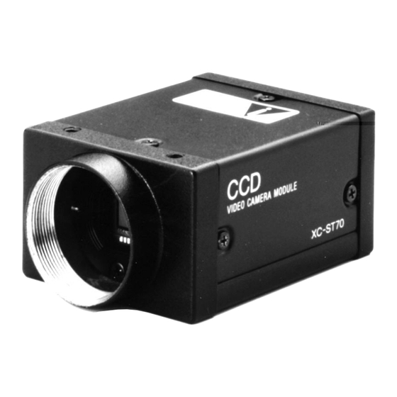
- Page 1 CCD B/W VIDEO CAMERA MODULE XC-ST70/70CE User’s uide (Ver. 1.0) — English —...
-
Page 2: Table Of Contents
XC-ST70/70CE Table of Contents OUTLINE ......................... 1 MAIN FEATURES ....................1 SYSTEM CONFIGURATION ................... 2 MAIN SPECIFICATIONS ..................3 CONNECTION DIAGRAM ..................4 LOCATION OF PARTS AND OPERATION ............. 5 PHASE CONDITIONS OF EXTERNAL SYNCHRONIZATION ........ 6 ELECTRONIC SHUTTER ..................7 RESTART RESET (R.R) .................. -
Page 3: Outline
XC-ST70/70CE OUTLINE The XC-ST70/70CE is a compact, lightweight black-and-white camera module using the latest technology and a 2/3- inch new-generation CCD. Each mode can be set by selecting the switches on the rear panel. The XC-ST70/70CE provides an external trigger shutter that can catch a high-speed moving subject using an external signal. This enables a still image to be read in arbitrary timing. -
Page 4: System Configuration
XC-ST70/70CE SYSTEM CONFIGURATION The components making up the system based on XC-ST70/ST70CE video camera are as follows. Camera cables Video camera module Camera adaptor CCXC-12P02N (2 m) XC-ST70/70CE DC-700/700CE CCXC-12P05N (5 m) CCXC-12P10N (10 m) CCXC-12P25N (25 m) Junction box Tripod adaptor C-mount lenses Close-up ring kit... -
Page 5: Main Specifications
XC-ST70/70CE MAIN SPECIFICATIONS Image pickup device: 2/3-inch interline transfer CCD Electronic shutter Number of effective pixels XC-ST70: 1/100 to 1/10,000 seconds XC-ST70: 768(H) x 494(V) XC-ST70CE: 1/120 to 1/10,000 seconds XC-ST70CE: 752(H) x 582(V) External trigger shutter CCD horizontal driving frequency XC-ST70: 1/4 to 1/10,000 seconds XC-ST70:... -
Page 6: Connection Diagram
XC-ST70/70CE C-mount lens VIDEO OUT HD/VD VCL-16Y-M TRIG Camera adaptor (Standard) DC-700/CE (Conforms to new EIAJ and uses 12-pin assignment.) VCL-08YM XC-ST70/70CE VIDEO OUT HD/VD Camera cable VCL-12YM Camera adaptor CCXC-12P02N CCXC-12P05N DC-777/CE Tripod adaptor (No trigger input terminal is provided.) CCXC-12P10N VCT-ST70I CCXC-12P25N... -
Page 7: Location Of Parts And Operation
LOCATION OF PARTS AND OPERATION XC-ST70/70CE 1 Lens mount section A commercial C-mount lens as well as a Sony standard lens can be used. 2 Camera mounting reference hole These screw holes are positionned with VIDEO CAMERA MODULE high precision related to CCD sensor. -
Page 8: Phase Conditions Of External Synchronization
XC-ST70/70CE PHASE CONDITIONS OF EXTERNAL SYNCHRONIZATION External synchronization for each mode • For normal video/normal shutter Continuous HD/VD signal (should conform to EIA and CCIR frequencies in the timing shown in the figure below.) • For Restart Reset (RR)/external trigger shutter Continuous HD signal. -
Page 9: Electronic Shutter
XC-ST70/70CE ELECTRONIC SHUTTER Two types of electronic shutter are provided “normal shutter and external trigger shutter”. The electronic shutter speed and type can be set using the DIP switch on the rear panel. DIP switch on the rear panel Normal shutter This mode provides continuous video output with the electronic shutter selected by switches to clearly capture a high-speed moving object. -
Page 10: External Trigger Shutter
XC-ST70/70CE ELECTRONIC SHUTTER External trigger shutter These modes are used to capture one image (one field) per trigger pulse. Set DIP switches 6, 7, and 8 on the rear panel to mode 1 or 2. (Refer to the table below.) When the trigger pulse width is 1/3 sec or more, the output signal is switched to a normal video signal. - Page 11 XC-ST70/70CE ELECTRONIC SHUTTER Specifications of trigger pulse When using a trigger pulse like shown below, set the TRIG polarity selector switch on the rear panel to + : A: 2 to 5.0 V B: 0 to 0.6 V T: 2 s to 1/4 s, 100 s to 1/4 s when setting the shutter speed using DIP switch When using a trigger pulse like shown below, set the TRIG polarity selector switch on the rear panel to –...
-
Page 12: Restart Reset (R.r)
XC-ST70/70CE RESTART RESET (R.R) The information on one screen can be extracted at any time by inputting a restart/reset signal (HD/VD) from the outside. To enter this mode, set DIP switches 6, 7, and 8 on the rear panel of a camera as shown in the table below. The setting is especially effective for the following operation. - Page 13 XC-ST70/70CE RESTART RESET (R.R) Example 2 of long exposure EXT HD Continuous signal: 15.734 kHz (XC-ST70), 15.625 kHz (XC-ST70CE) Allowable frequency value 1% EXT VD VD interval(T): 262.5H or more (XC-ST70), 312.5H or more (XC-ST70CE) and less than 1 second (Recommended) Four or more VD pulses are required.
-
Page 14: Frame Image Output With Strobe Light
XC-ST70/70CE FRAME IMAGE OUTPUT WITH STROBE LIGHT A full frame image with vertical resolution of 485 lines (XC-ST70) or 575 lines (XC-ST70CE) can be obtained with a strobe light by firing the strobe when the exposure time of the two fields overlap. Timing and conditions <Timing chart by restart/reset>... -
Page 15: Output Waveform Timing Chart
XC-ST70/70CE • XC-ST70 (EIA) OUTPUT WAVEFORM TIMING CHART Timing chart of horizontal output waveform 91 (6.36 s) output signal Effective total pixel Dummy 69.8 ns pixel Optical black portion Horizontal transfer stop period Optical black portion Horizontal blanking period (11.0 s) Output video period Camera video output signal... - Page 16 XC-ST70/70CE • XC-ST70 (EIA) ELECTRONIC SHUTTER OUTPUT WAVEFORM TIMING CHART Timing chart of vertical output waveform (2:1 interlaced field integration) Odd field (262.5 H) Even field (262.5 H) 253.5 H 253.5 H output signal 242.5 242.5 Empty Empty transfer transfer Camera Optical black portion Optical black portion...
- Page 17 XC-ST70/70CE • XC-ST70CE (CCIR) OUTPUT WAVEFORM TIMING CHART Timing chart of horizontal output waveform (6.91 s) output signal Effective total pixel 752 Dummy 70.5 ns Optical black pixel portion Horizontal transfer stop period Optical black portion Horizontal blanking period (12.1 s) Output video period Camera video output signal...
- Page 18 XC-ST70/70CE • XC-ST70CE (CCIR) ELECTRONIC SHUTTER OUTPUT WAVEFORM TIMING CHART Timing chart of vertical output waveform (2:1 interlaced field integration) Odd field (312.5 H) Even field (312.5 H) 7.5 H 305 H 7.5 H 305 H output signal 287.5 287.5 Empty Empty transfer...
-
Page 19: Timing Chart Of External Trigger Shutter - Mode 1
XC-ST70/70CE TIMING CHART OF EXTERNAL TRIGGER SHUTTER - MODE 1 (NON-RESET MODE) For setting the shutter speed using TRG width HD/VD input Continuous HD/VD input Mode transition state External input External trigger inhibition area shutter operation External trigger shutter operation Normal operation (50 ms) Trigger... - Page 20 XC-ST70/70CE TIMING CHART OF EXTERNAL TRIGGER SHUTTER - MODE 1 (NON-RESET MODE) For setting the shutter speed using TRG width HD/VD input Continuous HD input and single VD input Mode transition state External input External trigger inhibition area shutter operation External trigger shutter operation Normal operation (50 ms)
- Page 21 XC-ST70/70CE TIMING CHART OF EXTERNAL TRIGGER SHUTTER - MODE 1 (NON-RESET MODE) For setting the shutter speed using TRG width No HD/VD input (Internal synchronization) Mode transition state External input External trigger inhibition area shutter operation External trigger shutter operation Normal operation (50 ms) Trigger...
- Page 22 XC-ST70/70CE TIMING CHART OF EXTERNAL TRIGGER SHUTTER - MODE 1 (NON-RESET MODE) For setting the shutter speed using DIP switch HD/VD input Continuous HD/VD input Mode transition state External input External trigger inhibition area shutter operation External trigger shutter operation Normal operation (50 ms) Trigger...
- Page 23 XC-ST70/70CE TIMING CHART OF EXTERNAL TRIGGER SHUTTER - MODE 1 (NON-RESET MODE) For setting the shutter speed using DIP switch HD/VD input Continuous HD input and single VD input Mode transition state External input External trigger inhibition area shutter operation External trigger shutter operation Normal operation (50 ms)
- Page 24 XC-ST70/70CE TIMING CHART OF EXTERNAL TRIGGER SHUTTER - MODE 1 (NON-RESET MODE) For setting the shutter speed using DIP switch No HD/VD input (Internal synchronization) Mode transition state External input External trigger inhibition area shutter operation External trigger shutter operation Normal operation (50 ms) Trigger...
-
Page 25: Timing Chart Of External Trigger Shutter - Mode 2
XC-ST70/70CE TIMING CHART OF EXTERNAL TRIGGER SHUTTER - MODE 2 (RESET MODE) For setting the shutter speed using TRG width Mode transition state External input External trigger inhibition area shutter operation External trigger shutter operation Normal operation (50 ms) Trigger 1/3 s or more Exposure time Exposure... - Page 26 XC-ST70/70CE TIMING CHART OF EXTERNAL TRIGGER SHUTTER - MODE 2 (RESET MODE) For setting the shutter speed using DIP switch Mode transition state External input External trigger inhibition area shutter operation External trigger shutter operation Normal operation (50 ms) Trigger Exposure time 1/3 s Exposure...
-
Page 27: Dimensions
XC-ST70/70CE DIMENSIONS XC-ST70/70CE 2-M3 deep 4 (Unit: mm) VIDEO CAMERA MODULE XC-ST70 57.5 65.5 4-M3 deep 4 50 0.5... -
Page 28: Spectral Sensitivity Characteristics (Typical Value)
XC-ST70/70CE SPECTRAL SENSITIVITY CHARACTERISTICS (TYPICAL VALUE) 1000 Wavelength (nm) -
Page 29: Various Lens Selection
XC-ST70/70CE VARIOUS LENS SELECTION The following shows the various lens specifications of the accessories available. XC-ST70/70CE compatibility List of C-Mount Lens Model name VLC-08YM VLC-12YM VLC-16Y-M VLC-25Y-M VLC-50Y-M Focal distance (mm) 1: 1.4 1: 1.8 1: 1.4 1: 1.6 1: 2.8 Maximum aperture ratio Iris Manual... - Page 30 Technical information contained herein is for reference only and does not convey any license by any implication or otherwise under any intellectual property right or other right of Sony or third parties. Sony cannot assume responsibility for any right infringements arising out of the use of this information.
- Page 31 Sony Corporation 4-16-1, Okata, Atsugi-shi, Kanagawa-ken, 243-0021 Japan Tel: +81-46-227-2346 Fax: +81-46-227-2347 http://www.sony.com/professional Sony Electronics Inc. 1 Sony Drive Park Ridge, NJ 07656 Tel: +1-800-686-7669 Canada Sony of Canada Ltd. 115 Gordon Baker Rd, Toronto, Ontario M2H 3R6 Tel: +1-416-499-1414...
Need help?
Do you have a question about the XC-ST70 and is the answer not in the manual?
Questions and answers