Sony XC-HR70 Technical Manual
Ccd black-and-white video camera module
Hide thumbs
Also See for XC-HR70:
- Dimensions (2 pages) ,
- Operating instructions (2 pages) ,
- Brochure (4 pages)

Related Manuals for Sony XC-HR70


Summary of Contents for Sony XC-HR70
- Page 1 A-BAD-100-11 (1) CCD Black-and-White Video Camera Module Technical Manual XC-HR70 2002 Sony Corporation...
-
Page 2: Table Of Contents
Table of Contents Overview Features ..............3 System Components ..........4 Connection Diagram ..........4 Location and Function of Parts and Controls ..5 Front/Top/Bottom ............5 Rear Panel ..............6 Mode Settings Input/Output Specifications ........8 External HD/VD Input Phase Specifications ....8 External HD/VD Output Specifications ....... -
Page 3: Features
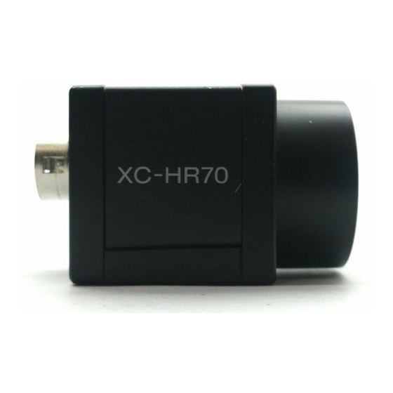
Overview Overview The XC-HR70 is a black-and-white video camera Electronic shutter module using a CCD (Charge Coupled Device) image sensor. You can choose from FL (flickerless) mode and a wide range of image speeds (1/125 to 1/20,000 s) for the best match to shooting conditions. -
Page 4: System Components
CCXC-12P02N(2 m) DC-700/700CE Video camera module CCXC-12P05N(5 m) XC-HR70 CCXC-12P10N(10 m) CCXC-12P25N(25 m) Tripod adaptor C-mount lens Close-up ring kit VCT-333I VCL-12YM (Sony) LO-77ERK (Insulated type) VF2509 (Canon) Connection Diagram XC-HR70 C-mount lens VIDEO OUT HD/VD TRIG VCL-12YM Camera cables... -
Page 5: Location And Function Of Parts And Controls
Overview Location and Function of Parts and Controls Front/Top/Bottom 1 Lens mount (C-mount) 2 Reference holes (at the top) 3 Reference holes/Tripod screw holes (at the bottom) 4 Reference holes (at the bottom) 1 Lens mount (C-mount) Attach any C-mount lens, such as the VCL-12YM 3 Reference holes/Tripod screw holes (at the standard lens, the VF2509 for high resolution, or other bottom) -
Page 6: Rear Panel
Overview Rear Panel 1 VIDEO OUT/DC IN/SYNC connector 2 Shutter speed / mode setting DIP switches 3 HD/VD signal input/output switch 4 M Gain control knob 5 75Ω termination switch For more information, see “Restart/Reset” (page 13) Note and “External Trigger Shutter” (page 16). Be sure to turn the power off before making switch settings. - Page 7 Overview VIDEO OUT/DC IN/SYNC connector pin assignments Rear panel Pin No. Camera sync output External mode (HD/VD) Restart/Reset External trigger shutter Ground Ground Ground Ground +12V DC +12V DC +12V DC +12V DC Video output (Ground) Video output (Ground) Video output 1 (Ground) Video output (Ground) Video output (Signal) Video output (Signal)
-
Page 8: Input/Output Specifications
Mode Settings Mode Settings Input/Output Specifications External HD/VD Input Phase Specifications External VD Falling edge Rising edge External HD Unit: Clock Standard center phase 1 Clk = 33.90 ns Make sure that the external HD and VD phases against During normal operation: HD phase 43.05 µs, VD the standard center phase are as shown in the figure. -
Page 9: External Hd/Vd Output Specifications
Mode Settings External HD/VD Output HD Input Specifications Specifications 2.0 – 5.0 Vp-p 4.5 V 2.0 µs – 5.0 µs 4.5 V • Input impedance: 75Ω or 10 kΩ or more. • Input amplitude 2.0 to 5.0 Vp-p (for both 75Ω termination ON and OFF) •... -
Page 10: Video Output Modes
Mode Settings Video Output Modes This unit has two video signal output modes. Select the mode with the binning mode switch (DIP switch 0) on the rear panel. DIP switches Rear panel Binning mode Binning OFF Signals for each independent pixel are output from the VIDEO OUT connector every 1/29.2 s (line sequential output). -
Page 11: About The Electronic Shutter
Mode Settings About the Electronic Shutter There are two shutter types: normal shutter and external trigger shutter. Select them with the DIP switches on the rear panel. DIP Switches on the Rear Panel Rear panel DIP switches Switches 1 to 4: Shutter speed switches* Switch 5: High-rate scan mode switch*... -
Page 12: External Trigger Shutter
Mode Settings Normal shutter speed settings 1/125 1/250 1/500 1/1000 1/2000 1/4000 1/10000 1/20000 1/100 (Unit: seconds) External Trigger Shutter By inputting an external trigger pulse, the camera is able to capture fast-moving objects clearly. For more information, see “External Trigger Shutter” (page 16). -
Page 13: Restart/Reset
Mode Settings Restart/Reset To Set Restart/Reset Mode The information on one screen can be extracted at any time by externally inputting restart/reset signals (HD/VD). To enter this mode, set the trigger shutter switches (6 to 8) on the rear panel of the camera as shown in the figure below. -
Page 14: To Use High-Rate Scan Mode (A)
Mode Settings To Use High-rate Scan Mode (A) As shown in the table below, you can increase the frame rate by setting the high-rate scan mode switch and the external VD width and frequency. The image obtained is centered as shown below. X lines 768 lines External VD... - Page 15 Mode Settings Binning OFF mode VD interval External VD width Effective lines BLKG interval Frame rate Tv [line] Tw [line] X [line] Tb [line] [frame/s] 796 (34.27 ms) High-rate scan OFF 768 (33.06 ms) 28 (1.205 ms) 29.2 387 (16.66 ms) 354 (15.24 ms) 33 (1.421 ms) 258 (11.11 ms)
-
Page 16: External Trigger Shutter
Mode Settings External Trigger Shutter When you set the trigger pulse width to 1/3 of a second Inputting an external trigger pulse enables the camera or more, the output signal changes to the normal to capture fast-moving objects clearly with precise VIDEO signal. -
Page 17: To Set The External Trigger Shutter
Mode Settings To Set the External Trigger Shutter There are two ways to set the shutter speed. Using trigger pulse width Set all DIP switches (1 to 4 on the rear panel) to OFF. Using the DIP switches on the rear panel You can obtain an arbitrary shutter speed by setting the trigger pulse width to the range of 2 µ... -
Page 18: To Use High-Rate Scan Mode (B)
Mode Settings To Use High-rate Scan Mode (B) The image output is terminated by inputting of the In external trigger shutter mode 1, you can increase the trigger falling edge. frame rate by setting the shutter speed to the trigger pulse width, and setting the high-rate scan mode Note that input of a trigger pulse is needed in the switch on the rear panel, the trigger interval, the... - Page 19 Mode Settings Binning OFF mode Trigger interval External VD width Effective lines BLKG interval Frame rate T [line] Tw [line] X [line] Tb [line] [frame/s] 796 (34.27 ms) High-rate scan OFF 766 (33.06 ms) 28 (1.205 ms) 29.2 387 (16.66 ms) 355 (15.28 ms) 30 (1.292 ms) 258 (11.11 ms)
-
Page 20: Timing Chart
Mode Settings Timing Chart When set to Mode 1 (Non-reset mode) Setting the shutter speed using trigger pulse width HD/VD input • Continuous VD input Mode transition state External input External trigger inhibition area External trigger shutter operation Normal operation* shutter operation (50 ms) Trigger*... - Page 21 Mode Settings Setting the shutter speed using trigger pulse width HD/VD input • Continuous HD input/Single VD input Mode transition state External input External trigger inhibition area External trigger shutter operation Normal operation* shutter operation (50 ms) Trigger* Trigger pulse width Exposure time Exposure time (Te)* (Te)*...
- Page 22 Mode Settings Setting the shutter speed using trigger pulse width No HD/VD input (Internal synchronization) Mode transition state External input inhibition area External trigger External trigger shutter operation (50 ms) Normal operation* shutter operation Trigger* Trigger pulse width Exposure time Exposure Exposure (Te)*...
- Page 23 Mode Settings Setting the shutter speed using DIP switches HD/VD input • Continuous VD input Mode transition state External input External trigger Normal inhibition area External trigger shutter operation shutter operation operation* (50 ms) 2 µ s to 250 ms Trigger* Trigger pulse width* Exposure time...
- Page 24 Mode Settings Setting the shutter speed using DIP switches HD/VD input • Continuous HD input/Single VD input Mode transition state External input External trigger inhibition area External trigger shutter operation Normal operation* shutter operation (50 ms) 2 µ s to 250 ms Trigger* Trigger pulse width* Exposure time...
- Page 25 Mode Settings Setting the shutter speed using DIP switches No HD/VD input (Internal synchronization) Mode transition state External input Normal External trigger inhibition area External trigger shutter operation shutter operation operation* (50 ms) 2 µ s to 250 ms Trigger* Trigger pulse width* Exposure time (Te)* Exposure time (Te)*...
- Page 26 Mode Settings When set to Mode 2 (Reset mode) Setting the shutter speed using trigger pulse width Mode transition state External input inhibition area External trigger (50 ms) External trigger shutter operation Normal operation* shutter operation Trigger* Trigger pulse width* Exposure time (Te)* Exposure time (Te)*...
- Page 27 Mode Settings Setting the shutter speed using the DIP switches Mode transition state External input inhibition area External trigger (50 ms) External trigger shutter operation Normal operation* shutter operation 2 µ s to 250 ms Trigger* Trigger pulse width* Exposure time (Te)* Exposure time (Te)* Video out*...
-
Page 28: Main Specifications
Specifications Specifications White clip 820 mV ±70 mV Main Specifications Read mode Normal mode/Bining mode Shutter External trigger shutter Shutter speed External trigger shutter: 1/4 to Items without specific conditions indicated are the 1/100,000 s values set at the factory. Power requirements +12 V DC (range: +10.5 to +15 V) Image pickup system... -
Page 29: Spectral Sensitivity Characteristics (Typical Values)
Specifications Spectral Sensitivity Characteristics (Typical Values) An example of spectral sensitivity characteristics (without taking the characteristics of the lens or the characteristics of the light source into consideration): Relative Response 1000 Wave Length (nm) -
Page 30: Ccd Output Waveform Timing Chart
Specifications CCD Output Waveform Timing Chart Horizontal Output Waveform Timing Chart 1 horizontal scan period 1270 (43.05 µ s) (36 µ s) 33.9 ns output signal Horizontal Optical Dummy transfer stop Effective total pixels 1034 black bits period Optical Output video period 1024 Horizontal blanking period 246 black (8.34 µ... - Page 31 Specifications Vertical Output Waveform Timing Chart (Binning OFF) 796 H (387 µ s) (387 µ s) CCD output signal 2 3 4 5 2 3 4 5 Optical Optical Dummy Optical Dummy Optical black black black bits* black bits* Camera video Vertical blanking period (28 H) Vertical blanking period (28 H) output signal...
-
Page 32: Dimensions
Technical information contained herein is for reference only and does not convey any license by any implication or otherwise under any intellectual property right or other right of Sony or third parties. Sony cannot assume responsibility for any right infringements arising out of the use of this information.
Need help?
Do you have a question about the XC-HR70 and is the answer not in the manual?
Questions and answers