Table of Contents
Advertisement
Advertisement
Table of Contents

Related Manuals for Asus P7H55 DVI


Summary of Contents for Asus P7H55 DVI
- Page 1 P7H55-M...
- Page 2 Product warranty or service will not be extended if: (1) the product is repaired, modified or altered, unless such repair, modification of alteration is authorized in writing by ASUS; or (2) the serial number of the product is defaced or missing.
-
Page 3: Table Of Contents
ASUS Overclocking Features ............. 1-3 1.3.3 ASUS Unique Features ............... 1-3 1.3.4 ASUS Power Solutions ............... 1-3 1.3.5 ASUS Quiet Thermal Solutions ........... 1-4 1.3.6 ASUS Crystal Sound ..............1-4 1.3.7 ASUS EZ DIY ................1-4 Chapter 2: Hardware information Before you proceed ................... -
Page 4: Contents
BIOS setup Knowing BIOS .................... 3-1 Updating BIOS .................... 3-1 3.2.1 ASUS Update utility..............3-2 3.2.2 ASUS EZ Flash 2 utility ............... 3-4 3.2.3 ASUS CrashFree BIOS 3 utility........... 3-5 3.2.4 ASUS BIOS Updater ..............3-6 BIOS setup program .................. 3-9 3.3.1... - Page 5 Boot Settings Configuration ............3-33 3.8.3 Security ..................3-34 Tools menu ....................3-36 3.9.1 ASUS O.C. Profile ..............3-36 3.9.2 AI NET 2 ..................3-37 3.9.3 ASUS EZ Flash 2 ..............3-37 3.9.4 Express Gate ................3-38 3.10 Exit menu ....................3-39...
- Page 6 4.2.1 Running the support DVD ............4-1 4.2.2 Obtaining the software manuals..........4-2 Software information ................. 4-3 4.3.1 ASUS PC Probe II ............... 4-3 4.3.2 ASUS AI Suite ................4-4 4.3.3 ASUS Fan Xpert................4-5 4.3.4 ASUS TurboV ................4-6 4.3.5...
-
Page 7: Notices
Complying with the REACH (Registration, Evaluation, Authorisation, and Restriction of Chemicals) regulatory framework, we published the chemical substances in our products at ASUS REACH website at http://green.asus.com/english/REACH.htm. DO NOT throw the motherboard in municipal waste. This product has been designed to enable proper reuse of parts and recycling. -
Page 8: Safety Information
Safety information Electrical safety • To prevent electrical shock hazard, disconnect the power cable from the electrical outlet before relocating the system. • When adding or removing devices to or from the system, ensure that the power cables for the devices are unplugged before the signal cables are connected. If possible, disconnect all power cables from the existing system before you add a device. -
Page 9: About This Guide
Where to find more information Refer to the following sources for additional information and for product and software updates. ASUS websites The ASUS website provides updated information on ASUS hardware and software products. Refer to the ASUS contact information. Optional documentation Your product package may include optional documentation, such as warranty flyers, that may have been added by your dealer. -
Page 10: Conventions Used In This Guide
Conventions used in this guide To ensure that you perform certain tasks properly, take note of the following symbols used throughout this manual. DANGER/WARNING: Information to prevent injury to yourself when trying to complete a task. CAUTION: Information to prevent damage to the components when trying to complete a task. -
Page 11: P7H55-M Pro Specifications Summary
* Hyper DIMM support is subject to the physical characteristics of individual CPUs. Some hyper DIMMs only support one DIMM per channel. Please refer to Memory QVL for details. ** Refer to www.asus.com or this user manual for the Memory QVL (Qualified Vendors Lists) Expansion Slots 1 x PCI Express 2.0 x16 slot... - Page 12 ASUS Power Solutions: - ASUS EPU - 4+2 Phase Power Design ASUS Express Gate ASUS Quiet Thermal Solution: - ASUS Fanless Design: Heat-sink solution - ASUS Fan Xpert ASUS EZ DIY: - ASUS Q-DIMM - ASUS O.C. Profile - ASUS CrashFree BIOS 3...
- Page 13 BIOS Features 64 Mb Flash ROM, SPI, AMI BIOS, PnP, DMI 2.0, WfM 2.0, SM BIOS 2.5, ACPI 2.0a, Multi-language BIOS, ASUS EZ Flash 2, ASUS CrashFree BIOS 3 Manageability WfM 2.0, DMI 2.0, WOL by PME, WOR by PME, PXE...
-
Page 15: Chapter 1: Product Introduction
® The motherboard delivers a host of new features and latest technologies, making it another standout in the long line of ASUS quality motherboards! Before you start installing the motherboard, and hardware devices on it, check the items in your package with the list below. -
Page 16: Special Features
Special features 1.3.1 Product highlights Intel LGA1156 Lynnfield / Clarkdale Processor Ready ® This motherboard supports the latest Intel Lynnfield and Clarkdale processors in LGA1156 ® package, which has memory and PCI Express controller integrated to support 2-channel (4 DIMMs) DDR3 memory and 16 PCI Express 2.0 lanes providing great graphics performance. Intel Lynnfield and Clarkdale processors are the most powerful and energy efficient CPUs in ®... -
Page 17: Asus Overclocking Features
ASUS Overclocking Features TurboV Feel the adrenaline rush of real-time O.C. – now a reality with the ASUS TurboV. This easy O.C. tool allows you to overclock without exiting or rebooting the OS; and its user-friendly interface makes overclock with just a few clicks away. Moreover, the ASUS OC profiles in TurboV provides the best O.C. -
Page 18: Asus Quiet Thermal Solutions
Fan Xpert ASUS Fan Xpert intelligently allows users to adjust both the CPU and chassis fan speed according to different ambient temperature, which is caused by different climate conditions in different geographic regions and system loading. Built-in variety of useful profiles offer flexible controls of fan speed to achieve a quiet and cool environment. - Page 19 ASUS CrashFree BIOS 3 The ASUS CrashFree BIOS 3 allows users to restore corrupted BIOS data from a USB flash disk containing the BIOS file. Refer to page 3-5 for details. ASUS O.C. Profile Freely share and distribute favorite overclocking settings. The motherboard features the ASUS O.C.
- Page 20 Chapter 1: Product Introduction...
-
Page 21: Chapter 2: Hardware Information
ON, in sleep mode, or in soft-off mode. This is a reminder that you should shut down the system and unplug the power cable before removing or plugging in any motherboard component. The illustration below shows the location of the onboard LED. ASUS P7H55-M PRO... -
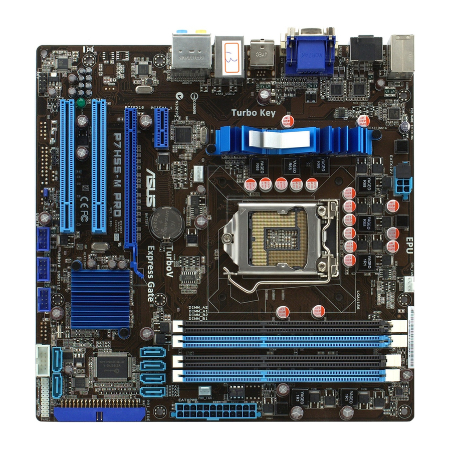
Page 22: Motherboard Overview
Motherboard overview 2.2.1 Motherboard layout Refer to 2.7 Connectors for more information about rear panel connectors and internal connectors. Chapter 2: Hardware information... -
Page 23: Layout Contents
Serial port connector (10-1 pin COM1) 2-30 USB connectors (10-1 pin USB78, USB910, USB1112) 2-30 Clear RTC RAM (3-pin CLRTC) 2-22 Digital audio connector (4-1 pin SPDIF_OUT) 2-32 Front panel audio connector (10-1 pin AAFP) 2-32 Standby power LED ASUS P7H55-M PRO... -
Page 24: Placement Direction
2.2.3 Placement direction When installing the motherboard, ensure that you place it into the chassis in the correct orientation. The edge with external ports goes to the rear part of the chassis as indicated in the image below. 2.2.4 Screw holes Place eight screws into the holes indicated by circles to secure the motherboard to the chassis. -
Page 25: Central Processing Unit (Cpu)
Contact your retailer immediately if the PnP cap is missing, or if you see any damage to the PnP cap/socket contacts/motherboard components. ASUS will shoulder the cost of repair only if the damage is shipment/ transit-related. - Page 26 Lift the load lever in the direction of the arrow until the load plate is completely lifted. Load plate Remove the PnP cap from the CPU socket by lifting the tab only. PnP cap Cap tab Position the CPU over the socket, ensuring that the gold triangle is on the bottom-left corner of the socket, and then CPU notches...
- Page 27 Close the load plate (A), and then push down the load lever (B), ensuring that the front edge of the load plate slides under the retention lock (C). Insert the load lever under the retention tab. ASUS P7H55-M PRO...
-
Page 28: Installing The Cpu Heatsink And Fan
2.3.2 Installing the CPU heatsink and fan The Intel LGA1156 processor requires a specially designed heatsink and fan assembly to ® ensure optimum thermal condition and performance. • When you buy a boxed Intel ® processor, the package includes the CPU fan and heatsink assembly. -
Page 29: Uninstalling The Cpu Heatsink And Fan
Rotate each fastener counterclockwise. Pull up two fasteners at a time in a diagonal sequence to disengage the heatsink and fan assembly from the motherboard. Carefully remove the heatsink and fan assembly from the motherboard. ASUS P7H55-M PRO... -
Page 30: System Memory
System memory 2.4.1 Overview The motherboard comes with four Double Data Rate 3 (DDR3) Dual In-line Memory Modules (DIMM) sockets. A DDR3 module has the same physical dimensions as a DDR2 DIMM but is notched differently to prevent installation on a DDR2 DIMM socket. DDR3 modules are developed for better performance with less power consumption. -
Page 31: Memory Configurations
3.5 Ai Tweaker menu for manual memory frequency adjustment. • For system stability, use a more efficient memory cooling system to support a full memory load (4 DIMMs) or overclocking condition. ASUS P7H55-M PRO 2-11... - Page 32 P7H55-M PRO Motherboard Qualified Vendors Lists (QVL) DDR3-2133MHz capability for Intel CPU without integrated GPU (Lynnfield) DIMM socket support (Optional) Vendor Part No. Size SS/DS Chip Brand Chip NO. Timing Voltage GEIL GE34GB2133C9DC(XMP) 4GB(2 x 2GB) DS 9-9-9-28 1.65 • •...
- Page 33 1.65 • • OCZ3G1600LV6GK 6GB(3 x 2GB) 8-8-8 1.65 • • OCZ3X1600LV6GK(XMP) 6GB(3 x 2GB) 8-8-8 1.65 • • OCZ3X1600LV6GK(XMP) 6GB(3 x 2GB) 8-8-8 1.65 • • Super Talent WB160UX6G8(XMP) 6GB(3 x 2GB) • • • ASUS P7H55-M PRO 2-13...
- Page 34 M378B2873EH1-CH9 SAMSUNG K4B1G0846E • • SAMSUNG M378B5673EH1-CH9 SAMSUNG K4B1G0846E • • • Asint SLZ3128M8-EDJE ELPIDA J1108BASE-DJ-E • • ASUS • • AQ28M72D8BJH9S SAMSUNG K4B1G0846D(ECC) • • • AQ56M72E8BJH9S SAMSUNG K4B1G0846D(ECC) • • • BUFFALO FSH1333D3G-T3G(XMP) 3GB(3 x 1GB) SS 7-7-7-20 - •...
- Page 35 SAMSUNG K4B1G0846D • • Transcend TS256MLK64V3U SAMSUNG K4B1G0846D • • Asint SLY3128M8-EDJ Asint DDRIII1208-DJ • • Asint SLY3128M8-EDJE ELPIDA J1108BASE-DJ-E • • • AQ28M64A8BJH9S SAMSUNG K4B1G0846E • • • AQ28M72D8BJH9S SAMSUNG K4B1G0846D(ECC) - • • • ASUS P7H55-M PRO 2-15...
- Page 36 P7H55-M PRO Motherboard Qualified Vendors Lists (QVL) DDR3-1333MHz capability for Intel CPU with integrated GPU (Clarkdale) DIMM socket support Timing Vendor Part No. Size Chip Brand Chip NO. Voltage (Optional) Dimm(Bios) AQ56M64B8BJH9S SAMSUNG K4B1G0846D • • AQ56M72E8BJH9S SAMSUNG K4B1G0846D(ECC) - •...
- Page 37 Hyper DIMM support is subject to the physical characteristics of individual CPUs. • According to Intel spec definition, DDR3-1600 is supported for one DIMM per channel only. ASUS exclusively provides two DDR3-1600 DIMM support for each memory channel. • According to Intel CPU spec, CPUs with a core frequency of 2.66G support the maximum DIMM frequency of up to DDR3-1333.
-
Page 38: Installing A Dimm
2.4.3 Installing a DIMM Ensure to unplug the power supply before adding or removing DIMMs or other system components. Failure to do so may cause severe damage to both the motherboard and the components. Unlock a DIMM socket by pressing DIMM notch the retaining clip outward. -
Page 39: Expansion Slots
When using PCI cards on shared slots, ensure that the drivers support “Share IRQ” or that the cards do not need IRQ assignments. Otherwise, conflicts will arise between the two PCI groups, making the system unstable and the card inoperable. Refer to the table on the next page for details. ASUS P7H55-M PRO 2-19... -
Page 40: Interrupt Assignments
2.5.3 Interrupt assignments Standard interrupt assignments Priority Standard function System Timer Keyboard Controller – Redirect to IRQ#9 Communications Port (COM1)* IRQ Holder for PCI Steering* Reserved Reserved System CMOS/Real Time Clock IRQ Holder for PCI Steering* IRQ Holder for PCI Steering* IRQ Holder for PCI Steering* Reserved Numeric Data Processor... -
Page 41: Pci Slots
This motherboard has one PCI Express 2.0 x16 slots that support PCI Express 2.0 x16 graphics cards complying with the PCI Express specifications. Refer to the figure below for the location of the slot. PCI slot 2 PCI slot 1 PCIe 2.0 x16_1 slot PCIe 2.0 x1_1 (2.5GT/s; gray slot) ASUS P7H55-M PRO 2-21... -
Page 42: Jumper
Jumper Clear RTC RAM (3-pin CLRTC) This jumper allows you to clear the Real Time Clock (RTC) RAM in CMOS. You can clear the CMOS memory of date, time, and system setup parameters by erasing the CMOS RTC RAM data. The onboard button cell battery powers the RAM data in CMOS, which include system setup information such as system passwords. -
Page 43: Connectors
10. Audio I/O ports** *and **: Refer to the tables on the next page for LAN port and audio port definitions. ***: Refer to the notes and troubleshooting on monitor overscan / underscan problem on the next pages. ASUS P7H55-M PRO 2-23... -
Page 44: Lan Port Led Indications
*LAN port LED indications ACT/LINK SPEED Activity Link LED Speed LED Status Description Status Description No link 10 Mbps connection ORANGE Linked ORANGE 100 Mbps connection LAN port BLINKING Data activity GREEN 1 Gbps connection ** Audio 2, 4, 6, or 8-channel configuration Port Headset 4-channel... - Page 45 Click Display > General Settings and select a Resolution. Click Apply. Or you can click Display > General Settings > Scaling > Customize Aspect Ratio. Move the Horizontal Scaling and Vertical Scaling sliders and then click Apply. ASUS P7H55-M PRO 2-25...
-
Page 46: Audio I/O Connections
2.7.2 Audio I/O connections Audio I/O ports Connect to Headphone and Mic Connect to Stereo / 2.1-channel Speakers 2-26 Chapter 2: Hardware information... - Page 47 Connect to 4.1-channel Speakers Connect to 5.1-channel Speakers Connect to 7.1-channel Speakers ASUS P7H55-M PRO 2-27...
-
Page 48: Internal Connectors
2.7.3 Internal connectors IDE connector (40-1 pin PRI_IDE) The onboard IDE connector is for the Ultra DMA 133/100 signal cable. There are three connectors on each Ultra DMA 133/100 signal cable: blue, black, and gray. Connect the blue connector to the motherboard’s IDE connector, then select one of the following modes to configure your device. - Page 49 These connectors connect to Serial ATA hard disk drives and optical disc drives via Serial ATA signal cables. You must install Windows ® XP Service Pack 2 or later versions before using Serial ATA hard disk drives. ASUS P7H55-M PRO 2-29...
- Page 50 USB connectors (10-1 pin USB78; USB910; USB1112) These connectors are for USB 2.0 ports. Connect the USB module cable to any of these connectors, then install the module to a slot opening at the back of the system chassis. These USB connectors comply with USB 2.0 specification that supports up to 480 Mbps connection speed.
- Page 51 These are not jumpers! Do not place jumper caps on the fan connectors! • The CPU_FAN connector supports the CPU fan of maximum 2A (24 W) fan power. • Only the CPU_FAN and CHA_FAN 1 connectors support the ASUS FAN Xpert feature. ASUS P7H55-M PRO 2-31...
- Page 52 Digital audio connector (4-1 pin SPDIF_OUT) This connector is for an additional Sony/Philips Digital Interface (S/PDIF) port(s). Connect the S/PDIF Out module cable to this connector, then install the module to a slot opening at the back of the system chassis. The S/PDIF module is purchased separately.
-
Page 53: Atx Power Connectors
The system may become unstable or may not boot up if the power is inadequate. • If you are uncertain about the minimum power supply requirement for your system, refer to the Recommended Power Supply Wattage Calculator at http://support.asus. com/PowerSupplyCalculator/PSCalculator.aspx?SLanguage=en-us for details. PSU suggested list Seventeam ST-522HLP T.C.STAR D420... -
Page 54: System Panel Connector
System panel connector (20-8 pin PANEL) This connector supports several chassis-mounted functions. • System power LED (2-pin PLED) This 2-pin connector is for the system power LED. Connect the chassis power LED cable to this connector. The system power LED lights up when you turn on the system power, and blinks when the system is in sleep mode. -
Page 55: Starting Up For The First Time
BIOS setting. Pressing the power switch for more than four seconds lets the system enter the soft-off mode regardless of the BIOS setting. Refer to section 3.7 Power Menu in Chapter 3 for details. ASUS P7H55-M PRO 2-35... - Page 56 2-36 Chapter 2: Hardware information...
-
Page 57: Chapter 3: Bios Setup
Refer to the corresponding sections for details on these utilities. Save a copy of the original motherboard BIOS file to a USB flash drive in case you need to restore the BIOS in the future. Copy the original motherboard BIOS using the ASUS Update utility. -
Page 58: Asus Update Utility
3.2.1 ASUS Update utility The ASUS Update is a utility that allows you to manage, save, and update the motherboard BIOS in Windows environment. The ASUS Update utility allows you to: ® • Save the current BIOS file • Download the latest BIOS file from the Internet •... - Page 59 Auto Select. Click Next. Next. Follow the onscreen instructions to complete the update process. The ASUS Update utility is capable of updating itself through the Internet. Always update the utility to avail all its features. Updating the BIOS through a BIOS file...
-
Page 60: Asus Ez Flash 2 Utility
3.2.2 ASUS EZ Flash 2 utility The ASUS EZ Flash 2 feature allows you to update the BIOS without using an OS-based utility. Before you start using this utility, download the latest BIOS from the ASUS website at www. asus.com. -
Page 61: Asus Crashfree Bios 3 Utility
The BIOS file in the motherboard support DVD may be older than the BIOS file published on the ASUS official website. If you want to use the newer BIOS file, download the file at support.asus.com and save it to a USB flash drive. -
Page 62: Asus Bios Updater
3.2.4 ASUS BIOS Updater The ASUS BIOS Updater allows you to update BIOS in DOS environment. This utility also allows you to copy the current BIOS file that you can use as a backup when the BIOS fails or gets corrupted during the updating process. - Page 63 ASUSTek BIOS Updater for DOS V1.00b [09/06/22] FLASH TYPE: MXIC 25L1605A Current ROM Update ROM BOARD: P7H55-M PRO BOARD: Unknown VER: 0113 VER: Unknown DATE: 11/03/2009 DATE: Unknown PATH: BIOS backup is done! Press any key to continue. Note Saving BIOS: ASUS P7H55-M PRO...
- Page 64 Updating the BIOS file To update the BIOS file using BIOS Updater At the FreeDOS prompt, type bupdater /pc /g and press <Enter>. D:\>bupdater /pc /g The BIOS Updater screen appears as below. ASUSTek BIOS Updater for DOS V1.00b [09/06/22] FLASH TYPE: MXIC 25L1605A Current ROM...
-
Page 65: Bios Setup Program
For changing the advanced system settings Power For changing the advanced power management (APM) configuration Boot For changing the system boot configuration Tools For configuring options for special functions Exit For selecting the exit options and loading default settings ASUS P7H55-M PRO... -
Page 66: Navigation Keys
3.3.3 Navigation keys At the bottom right corner of a menu screen are the navigation keys for that particular menu. Use the navigation keys to select items in the menu and change the settings. The navigation keys may differ from one screen to another. 3.3.4 Menu items The highlighted item on the menu bar displays the specific items for that menu. -
Page 67: Main Menu
The BIOS automatically detects the values of the dimmed items (Device, Vendor, Size, LBA Mode, Block Mode, PIO Mode, Async DMA, Ultra DMA, and SMART monitoring). These values are not user-configurable. These items show N/A if no SATA device is installed in the system. ASUS P7H55-M PRO 3-11... - Page 68 Type [Auto] Allows you to select the type of SATA drive installed. [Not Installed] Select this option if no SATA drive is installed. [Auto] Allows automatic selection of the appropriate SATA device type. [CDROM] Select this option if you are specifically configuring a CD-ROM drive. [ARMD] Select [ARMD] (ATAPI Removable Media Device) if your device is either a ZIP, LS-120, or MO drive.
-
Page 69: Storage Configuration
Disables or enables device write protection. This will be effective only if the device is accessed through BIOS. Configuration option: [Disabled] [Enabled] IDE Detect Time Out (Sec) [35] Selects the time out value for detecting ATA/ATAPI devices. Configuration options: [0] [5] [10] [15] [20] [25] [30] [35] ASUS P7H55-M PRO 3-13... -
Page 70: Ahci Configuration
3.4.3 AHCI Configuration This menu is the section for AHCI configuration. It appears only when you set the item Configure SATA as from the submenu of SATA Configuration to [AHCI]. BIOS SETUP UTILITY Main AHCI Settings SATA Port1 [Not Detected] SATA Port2 [Not Detected] SATA Port3 [Not Detected] SATA Port4 [Not Detected]... -
Page 71: Ai Tweaker Menu
Memory Profile (X.M.P.) Technology, choose this item to set the profile(s) supported by your memory module(s) for optimizing the system performance. The configuration options for the following sub-item vary depending on the DIMMs you install on the motherboard. ASUS P7H55-M PRO 3-15... - Page 72 D.O.C.P. D.O.C.P. • When using DIMMs with a frequncy higher than the Intel CPU spec, use this ASUS ® exclusive DRAM O.C. Profile function to overclock the DRAM. • Adjust BCLK frequency to obtain a better performance after applying the D.O.C.P function.
-
Page 73: Xtreme Phase Full Power Mode
The items in this menu allow you to set the DRAM timing control features. The configuration options for some of the following items vary depending on the DIMMs you install on the motherboard. 1st Information: 5-5-5-15-4-36-6-5-16 The values vary depending on your settings of the following sub-items: ASUS P7H55-M PRO 3-17... - Page 74 DRAM CAS# Latency [Auto] Configuration options: [Auto] [3 DRAM Clock] [4 DRAM Clock] – [10 DRAM Clock] [11 DRAM Clock] DRAM RAS# to CAS# Delay [Auto] Configuration options: [Auto] [3 DRAM Clock] [4 DRAM Clock] – [14 DRAM Clock] [15 DRAM Clock] DRAM RAS# PRE Time [Auto] Configuration options: [Auto] [3 DRAM Clock] [4 DRAM Clock] –...
-
Page 75: Cpu Differential Amplitude
VCore voltage may damage the CPU permanently, and setting a low VCore voltage may make the system unstable. 3.5.12 IMC Voltage [Auto] Allows you to set the CPU Integrated Memory Controller voltage. The values range from 1.10V to 1.20 with a 0.05V interval. ASUS P7H55-M PRO 3-19... -
Page 76: Dram Voltage
3.5.13 DRAM Voltage [Auto] Allows you to set the DRAM voltage. The values range from 1.2V to 2.20V with a 0.10V interval. According to Intel CPU spec, DIMM voltage below 1.65V is recommended to protect the CPU. 3.5.14 CPU PLL Voltage [Auto] Allows you to set the CPU PLL voltage. -
Page 77: Advanced Menu
Execute-Disable Bit Capability [Enabled] Intel(R) HT Technology [Enabled] Active Processor Cores [All] A20M [Disabled] Intel(R) SpeedStep(TM) Tech [Enabled] Intel(R) TurboMode Tech [Enabled] Intel(R) C-STATE Tech [Enabled] C State package limit setting [Auto] v02.61 (C)Copyright 1985-2009, American Megatrends, Inc. ASUS P7H55-M PRO 3-21... - Page 78 CPU Ratio Setting [Auto] Allows you to adjust the ratio between CPU Core Clock and BCLK Frequency. Use the <+> and <-> keys to adjust the value. The valid value ranges differently according to your CPU model. C1E Support [Enabled] [Enabled] Enables the C1E support function.
-
Page 79: Uncore Configuration
PCI MMIO Allocation: 4GB To 3072MB DISABLE: Do not allow Initiate Graphic Adapter [PEG/PCI] remapping of memory. iGPU Graphics Mode Select [Enabled, 32MB] iGPU Frequency [Auto] Current iGPU Frequency: 700 MHz DVMT Memory [Maximum DVMT] ASUS P7H55-M PRO 3-23... - Page 80 Memory Remap Feature [Enabled] [Disabled] Do not allow remapping of memory. [Enabled] Allows for the segment of system memory that was previously overwritten by PCI devices to be remapped above the total physical memory. Initiate Graphic Adapter [PEG/PCI] Allows you to select which graphics controller to use as the primary boot device. Configuration options: [iGPU] [PCI/iGPU] [PCI/PEG] [PEG/iGPU] [PEG/PCI] iGPU Graphics Mode Select [Enabled, 32MB] Allows you to select the amount of memory used by the integrated GPU.
-
Page 81: Onboard Devices Configuration
J-Micron PATA Controller [Enabled] [Enabled] Enables the J-Micron PATA controller. [Disabled] Disables the J-Micron PATA controller. Serial Port1 Address [3F8/IRQ4] Allows you to select the Serial Port1 base address. Configuration options: [Disabled] [3F8/IRQ4] [2F8/IRQ3] [3E8/IRQ4] [2E8/IRQ3] ASUS P7H55-M PRO 3-25... -
Page 82: Usb Configuration
3.6.4 USB Configuration The items in this menu allows you to change the USB-related features. Select an item then press <Enter> to display the configuration options. BIOS SETUP UTILITY Advanced USB Configuration Options Module Version - 2.24.5-13.4 Disabled Enabled USB Devices Enabled: 2 Hubs USB Functions [Enabled]... -
Page 83: Pcipnp
[No] When set to [No], BIOS configures all the devices in the system. 3.6.6 Intel VT-d [Disabled] [Disabled] Disables the Intel Virtualization Technology for Directed I/O. [Enabled] Enables the Intel Virtualization Technology for Directed I/O. ASUS P7H55-M PRO 3-27... -
Page 84: Power Menu
Power menu The Power menu items allow you to change the settings for the Advanced Power Management (APM). Select an item then press <Enter> to display the configuration options. BIOS SETUP UTILITY Main Ai Tweaker Advanced Power Boot Tools Exit Select the ACPI state Suspend Mode [Auto]... -
Page 85: Apm Configuration
Disables the Power On by a PS/2 keyboard. [Space Bar] Allows you to turn on the system by pressing the Space Bar key on the PS/2 keyboard. This feature requires an ATX power supply that provides at least 1A on the +5VSB lead. ASUS P7H55-M PRO 3-29... -
Page 86: Hardware Monitor
[Ctrl-Esc] Allows you to turn on the system by pressing the Ctrl key and Esc key of the PS/2 keyboard. This feature requires an ATX power supply that provides at least 1A on the +5VSB lead. [Power Key] Allows you to turn on the system by pressing the Power key on the PS/2 keyboard. - Page 87 Sets to [Turbo] to achieve maximum chassis fan speed. CPU Voltage, 3.3V Voltage, 5V Voltage, 12V Voltage The onboard hardware monitor automatically detects the voltage output through the onboard voltage regulators. Select Ignored if you do not want to detect this item. ASUS P7H55-M PRO 3-31...
-
Page 88: Boot Menu
Configuration options: [Removable Dev.] [Hard Drive] [ATAPI DVD-ROM] [Disabled] • To select the boot device during system startup, press <F8> when ASUS Logo appears. • To access Windows OS in Safe Mode, do any of the following: ®... -
Page 89: Boot Settings Configuration
Disables the full screen logo display feature. [Enabled] Enables the full screen logo display feature. Set this item to [Enabled] to use the ASUS MyLogo 2™ feature. AddOn ROM Display Mode [Force BIOS] [Force BIOS] The third-party ROM messages will be forced to display during the boot sequence. -
Page 90: Security
3.8.3 Security The Security menu items allow you to change the system security settings. Select an item then press <Enter> to display the configuration options. BIOS SETUP UTILITY Boot Security Settings <Enter> to change password. Supervisor Password : Not Installed <Enter>... - Page 91 Select this item to clear the user password. Password Check [Setup] [Setup] BIOS checks for user password when accessing the Setup utility. [Always] BIOS checks for user password both when accessing Setup and booting the system. ASUS P7H55-M PRO 3-35...
-
Page 92: Tools Menu
<Enter> to display the submenu. BIOS SETUP UTILITY Main Ai Tweaker Advanced Power Boot Tools Exit ASUS O.C. Profile AI NET 2 ASUS EZ Flash 2 Express Gate [Auto] Enter OS Timer [10 Seconds] Reset User Data [No] Select Screen ←→ Select Item ↑↓... -
Page 93: Ai Net 2
3.9.3 ASUS EZ Flash 2 Allows you to run ASUS EZ Flash 2. When you press <Enter>, a confirmation message appears. Use the left/right arrow key to select between [Yes] or [No], then press <Enter> to confirm your choice. Check section 3.2.2 ASUS EZ Flash 2 utility for details. -
Page 94: Express Gate
3.9.4 Express Gate [Auto] Allows you to enable or disable the ASUS Express Gate feature. The ASUS Express Gate feature is a unique instant-on environment that provides quick access to the Internet browser and Skype. Configuration options: [Disabled] [Enabled] [Auto] Enter OS Timer [10 Seconds] Sets countdown duration that the system waits at the Express Gate’s first screen... -
Page 95: Exit Menu
When you select this option or if you press <F5>, a confirmation window appears. Select Ok to load default values. Select Exit & Save Changes or make other changes before saving the values to the non-volatile RAM. ASUS P7H55-M PRO 3-39... - Page 96 3-40 Chapter 3: BIOS setup...
-
Page 97: Chapter 4: Software Support
The contents of the support DVD are subject to change at any time without notice. Visit the ASUS website at www.asus.com for updates. 4.2.1 Running the support DVD Place the support DVD into the optical drive. -
Page 98: Obtaining The Software Manuals
The software manual files are in Portable Document Format (PDF). Install the Adobe ® Acrobat Reader from the Utilities menu before opening the files. ® Click the Manual tab. Click ASUS Motherboard Utility Guide from the manual list on the left. The Manual folder of the support DVD appears. Double-click the folder of your selected software. -
Page 99: Software Information
Launching PC Probe II Install PC Probe II from the motherboard support DVD. Launch PC Probe II by clicking Start > All Programs > ASUS > PC Probe II > PC Probe II v1.xx.xx. The PC Probe II main window appears. -
Page 100: Asus Ai Suite
Launching AI Suite Install AI Suite from the motherboard support DVD. Launch AI Suite by clicking Start > All Programs > ASUS > AI Suite > AI Suite v1.xx. xx. The AI Suite main window appears. The AI Suite icon appears in the Windows notification area. -
Page 101: Asus Fan Xpert
4.3.3 ASUS Fan Xpert Asus Fan Xpert allows you to adjust both the CPU and chassis fan speeds according to different ambient temperatures and your PC’s system loading. The various fan profiles offer flexible controls of fan speeds to achieve a quiet and cool system environment. -
Page 102: Asus Turbov
4.3.4 ASUS TurboV ASUS TurboV allows you to easily overclock without exiting or rebooting the OS, and set up the best O.C. settings for different scenarios. Refer to the CPU documentation before adjusting CPU voltage settings. Setting a high voltage may damage the CPU permanently, and setting a low voltage may make the system unstable. -
Page 103: Asus Gpu Boost
DVD. • For system stability, all changes made in ASUS GPU Boost will not be saved to BIOS settings and will not be kept on the next system boot. Use the Save Profile function to save your customized overclocking settings and manually load the profile after Windows starts. -
Page 104: Asus Turbo Key
4.3.6 ASUS Turbo Key ASUS Turbo Key allows the user to turn the PC power button into a physical overclocking button. After the easy setup, Turbo Key can boost performances without interrupting ongoing work or games—with just one touch! Launching ASUS Turbo Key Install ASUS Turbo Key from the motherboard support DVD. -
Page 105: Asus Epu
4.3.7 ASUS EPU ASUS EPU is an energy-efficient tool that provides you with a total system power-saving solution. It detects the current computer loading and intelligently adjusts the power in real-time. With auto phase switching for components, the EPU automatically provides the most appropriate power usage via intelligent acceleration and overclocking. -
Page 106: Asus Express Gate
4.3.8 ASUS Express Gate ASUS Express Gate is an instant-on environment that gives you quick access to the Internet, Skype, and viewing your pictures. Within a few seconds of powering on your computer, you will be at the Express Gate menu where you can start the web browser, Skype, or other Express Gate applications. -
Page 107: Realtek ® High Definition Audio Utility
Device advanced Configuration settings option tabs Connector settings Analog and digital Control connector settings status window Information button Realtek HD Audio Manager for Windows XP Exit button Configuration options Minimize button Control settings window Information button ASUS P7H55-M PRO 4-11... - Page 108 4-12 Chapter 4: Software support...
-
Page 109: Asus Contact Information
+1-812-282-3777 +1-510-608-4555 Web site usa.asus.com Technical Support Telephone +1-812-282-2787 Support fax +1-812-284-0883 Online support support.asus.com ASUS COMPUTER GmbH (Germany and Austria) Address Harkort Str. 21-23, D-40880 Ratingen, Germany +49-2102-959911 Web site www.asus.de Online contact www.asus.de/sales Technical Support Telephone +49-1805-010923 Support Fax...
Need help?
Do you have a question about the P7H55 DVI and is the answer not in the manual?
Questions and answers