Table of Contents
Advertisement
Advertisement
Table of Contents

Related Manuals for Asus P7H55-M LE


Summary of Contents for Asus P7H55-M LE
- Page 1 P7H55-M LE P7H55-M LX P7H55-M LX2...
- Page 2 Product warranty or service will not be extended if: (1) the product is repaired, modified or altered, unless such repair, modification of alteration is authorized in writing by ASUS; or (2) the serial number of the product is defaced or missing.
-
Page 3: Table Of Contents
Contents Notices ......................v Safety information ..................vi About this guide ..................vi P7H55-M LE Series specifications summary ......... viii Chapter 1: Product introduction Before you proceed ..............1-1 Motherboard overview ..............1-2 1.2.1 Motherboard layout ............1-2 1.2.2 Layout contents ............... 1-2 Central Processing Unit (CPU) ........... - Page 4 Contents BIOS setup program ..............2-7 Main menu ..................2-8 2.3.1 System Time [xx:xx:xx] ........... 2-8 2.3.2 System Date [Day xx/xx/xxxx] ......... 2-8 2.3.3 Legacy Diskette A [1.44M, 3.5 in.] ........2-8 2.3.4 Language [English] ............2-8 2.3.5 SATA 1-6 ....................2-8 2.3.6 Storage Configuration .............
-
Page 5: Notices
Complying with the REACH (Registration, Evaluation, Authorisation, and Restriction of Chemicals) regulatory framework, we published the chemical substances in our products at ASUS REACH website at http://csr.asus.com/english/REACH.htm. DO NOT throw the motherboard in municipal waste. This product has been designed to enable proper reuse of parts and recycling. -
Page 6: Safety Information
Safety information Electrical safety • To prevent electric shock hazard, disconnect the power cable from the electric outlet before relocating the system. • When adding or removing devices to or from the system, ensure that the power cables for the devices are unplugged before the signal cables are connected. If possible, disconnect all power cables from the existing system before you add a device. -
Page 7: Conventions Used In This Guide
Refer to the following sources for additional information and for product and software updates. ASUS websites The ASUS website provides updated information on ASUS hardware and software products. Refer to the ASUS contact information. Optional documentation Your product package may include optional documentation, such as warranty flyers, that may have been added by your dealer. -
Page 8: P7H55-M Le Series Specifications Summary
Intel H55 Express Chipset: ® - 6 x Serial ATA 3.0 Gb/s connectors - 1 x Ultra DMA 100/66 connector (for P7H55-M LE only) - 1 x Floppy connector (for P7H55-M LE only) Realtek 8112L PCIe Gigabit LAN controller ®... - Page 9 1 x Front panel audio connector 1 x System panel connector 1 x S/PDIF Out connector (for P7H55-M LE and P7H55-M LX only) 1 x COM connector (for P7H55-M LE and P7H55-M LX only) 1 x IDE connector (for P7H55-M LE only)
-
Page 10: Chapter 1: Product Introduction
Chapter 1 Product introduction Thank you for buying an ASUS P7H55-M LE Series motherboard! ® Before you start installing the motherboard, and hardware devices on it, check the items in your motherboard package. Refer to page ix for the list of accessories. -
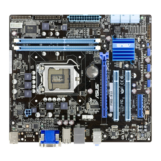
Page 11: Motherboard Overview
6. LPT connector (26-1 pin LPT) 1-15 14. Digital audio connector (4-1 pin SPDIF_OUT) 1-11 7. Floppy disk drive connector (34-1 pin FLOPPY) 1-14 15. Front panel audio connector (10-1 pin AAFP) 1-14 8. IDE connector (40-1 pin PRI_EIDE) 1-16 ASUS P7H55-M LE Series... -
Page 12: Central Processing Unit (Cpu)
Contact your retailer immediately if the PnP cap is missing, or if you see any damage to the PnP cap/socket contacts/motherboard components. ASUS will shoulder the cost of repair only if the damage is shipment/transit-related. • Keep the cap after installing the motherboard. ASUS will process Return Merchandise Authorization (RMA) requests only if the motherboard comes with the cap on the LGA1156 socket. -
Page 13: Memory Configurations
OS if you want to install 4GB or more memory on the ® motherboard. • This motherboard does not support DIMMs made up of 256 megabits (Mb) chips or less. P7H55-M LE Series Motherboard Qualified Vendors List (QVL) DDR3-1333MHz capability DIMM Timing... - Page 14 DDR3-1333MHz capability DIMM Timing Chip Support Vendor Part No. Size Chip No. DIMM Voltage Brand (BIOS) A* B* G.SKILL F3-10600CL9D-2GBNQ 1024MB G.SKILL • • G.SKILL F3-10666CL8D- 4096MB(Kit of 2 ) DS 8-8-8-8-24 1.35V(low • • 4GBECO(XMP) voltage) G.SKILL F3-10666CL8D-4GBHK(XMP) 4096MB(Kit of 2 ) DS 8-8-8-21 1.5-1.6V •...
- Page 15 • A*: Supports one module inserted into any slot as Single-channel memory configuration. • B*: Supports one pair of modules inserted into both the slots as one pair of Dual-channel memory configuration. Visit the ASUS website at www.asus.com for the latest QVL. ASUS P7H55-M LE Series...
-
Page 16: Expansion Slots
Expansion slots In the future, you may need to install expansion cards. The following sub-sections describe the slots and the expansion cards that they support. Unplug the power cord before adding or removing expansion cards. Failure to do so may cause you physical injury and damage motherboard components. -
Page 17: Jumpers
Normal Clear RTC (Default) P7H55-M LE Clear RTC RAM To erase the RTC RAM: Turn OFF the computer and unplug the power cord. Move the jumper cap from pins 1-2 (default) to pins 2-3. Keep the cap on pins 2-3 for about 5-10 seconds, then move the cap back to pins 1-2. -
Page 18: Connectors
Rear panel ports PS/2 Mouse port. This port is for a PS/2 mouse. COM port (for P7H55-M LE only). This 9-pin COM1 port is for serial devices. Video Graphics Adapter (VGA) port. This 15-pin port is for a VGA monitor or other VGA-compatible devices. -
Page 19: Internal Connectors
USB 2.0 ports 3, 4, 5, and 6. These four 4-pin Universal Serial Bus (USB) ports connect to USB 2.0/1.1 devices. DVI-D port (for P7H55-M LE and P7H55-M LX only). This port is for any DVI-D compatible device. DVI-D can’t be converted to output RGB Signal to CRT and isn’t compatible with DVI-I. - Page 20 XP Service Pack 2 or later version before using Serial ATA. ® Digital audio connector (4-1 pin SPDIF_OUT) (for P7H55-M LE and P7H55-M LX only) This connector is for an additional Sony/Philips Digital Interface (S/PDIF) port. SPDIF_OUT P7H55-M LE Digital audio connector The S/PDIF module is purchased separately.
-
Page 21: System Panel Connector
F_PANEL PIN 1 HD_LED RESET P7H55-M LE System panel connector • System power LED (2-pin PLED) This 2-pin connector is for the system power LED. Connect the chassis power LED cable to this connector. The system power LED lights up when you turn on the system power, and blinks when the system is in sleep mode. -
Page 22: Atx Power Connectors
The system may become unstable or may not boot up if the power is inadequate. • If you are uncertain about the minimum power supply requirement for your system, refer to the Recommended Power Supply Wattage Calculator at http://support.asus. com/PowerSupplyCalculator/PSCalculator.aspx?SLanguage=en-us for details. 1-13... - Page 23 AC97 front panel audio module to this connector, set the item to [AC97]. See section 2.4.3 Onboard Devices Configuration for details. Floppy disk drive connector (34-1 pin FLOPPY) (for P7H55-M LE only) This connector is for the floppy disk drive (FDD) signal cable. Insert one end of the cable to this connector, then connect the other end to the signal connector at the back of the floppy disk drive.
- Page 24 IDE connector (40-1 pin PRI_EIDE) (for P7H55-M LE only) The onboard IDE connector is for Ultra DMA 100/66 signal cable. There are three connectors on each Ultra DMA 100/66 signal cable: blue, black, and gray. Connect the blue connector to the motherboard’s IDE connector, then select one of the following...
- Page 25 Serial port connectors (10-1 pin COM2) (for P7H55-M LE and P7H55-M LX only) The connector is for a serial (COM) port. Connect the serial port module cable to the connector, then install the module to a slot opening at the back of the system chassis.
-
Page 26: Software Support
Place the Support DVD into the optical drive. The DVD automatically displays the Drivers menu if the Autorun function is enabled on your computer. The contents of the Support DVD are subject to change at any time without notice. Visit the ASUS website at www.asus.com for updates. Click an icon to display Support... -
Page 27: Chapter 2: Bios Information
BIOS in the future. Copy the original motherboard BIOS using the ASUS Update utility. 2.1.1 ASUS Update The ASUS Update is a utility that allows you to manage, save, and update the motherboard BIOS in Windows environment. ®... -
Page 28: Asus Ez Flash 2
Follow the onscreen instructions to complete the updating process. 2.1.2 ASUS EZ Flash 2 The ASUS EZ Flash 2 feature allows you to update the BIOS without using an OS-based utility. Before you start using this utility, download the latest BIOS file from the ASUS website at www.asus.com. -
Page 29: Asus Bios Updater
2.1.3 ASUS BIOS Updater The ASUS BIOS Updater allows you to update BIOS in DOS environment. This utility also allows you to copy the current BIOS file that you can use as a backup when the BIOS fails or gets corrupted during the updating process. - Page 30 When the Make Disk menu appears, select the FreeDOS command prompt item by pressing the item number. At the FreeDOS prompt, type d: and press <Enter> to switch the disk from Drive C (optical drive) to Drive D (USB flash drive). Welcome to FreeDOS (http://www.freedos.org)! C:\>d: D:\>...
-
Page 31: Updating The Bios File
Select the Load Setup Defaults item under the Exit BIOS menu. See section 2.8 Exit menu for details. • Ensure to connect all SATA hard disk drives after updating the BIOS file if you have disconnected them. ASUS P7H55-M LE Series... -
Page 32: Asus Crashfree Bios 3
2.1.4 ASUS CrashFree BIOS 3 ASUS CrashFree BIOS 3 is an auto recovery tool that allows you to restore the BIOS file when it fails or gets corrupted during the updating process. You can restore a corrupted BIOS file using the motherboard support DVD or a USB flash drive that contains the BIOS file. -
Page 33: Bios Setup Program
• The BIOS setup screens shown in this section are for reference purposes only, and may not exactly match what you see on your screen. • Visit the ASUS website at www.asus.com to download the latest BIOS file for this motherboard. -
Page 34: Main Menu
Legacy Diskette A [1.44M, 3.5 in.] Sets the type of floppy drive installed. Configuration options: [Disabled] [360K, 5.25 in.] [1.2M , 5.25 in.] [720K , 3.5 in.] [1.44M, 3.5 in.] [2.88M, 3.5 in.] This item appears only on P7H55-M LE. 2.3.4 Language [English] Allows you to choose the display language in BIOS. -
Page 35: Storage Configuration
Sets the configuration for the Serial ATA connectors supported by the Southbridge chip. Configuration options: [IDE] [AHCI] Due to Intel chipset driver support regulation, the AHCI mode is not supported in Windows XP environment. The AHCI mode is only supported by Windows Vista/7 with OS built-in driver. ASUS P7H55-M LE Series... -
Page 36: System Information
Hard Disk Write Protect [Disabled] Disables or enables device write protection. This will be effective only if device is accessed through BIOS. Configuration option: [Disabled] [Enabled] IDE Detect Time Out (Sec) [35] Selects the time out value for detecting ATA/ATAPI devices. Configuration options: [0] [5] [10] [15] [20] [25] [30] [35] 2.3.7 System Information... - Page 37 Setting this item to [Enabled] allows Legacy OSes to be compatible with APs. Configuration options: [Disabled] [Enabled] The following item appears only when you installed an Intel CPU that supports the ® Enhanced Intel SpeedStep Technology (EIST). ® ® ASUS P7H55-M LE Series 2-11...
-
Page 38: Chipset
Intel(R) SpeedStep(TM) Tech [Enabled] When this item is set to [Enabled], the CPU speed is controlled by the operating system. When this item is set to [Disabled], the CPU runs at its default speed. Configuration options: [Enabled] [Disabled] Intel(R) TurboMode Tech [Enabled] This item appears only if you set the CPU Ratio Setting item to [Auto]. - Page 39 Serial Port1 Address [3F8/IRQ4] Allows you to select the Serial Port1 base address. Configuration options: [Disabled] [3F8/IRQ4] [2F8/IRQ3] [3E8/IRQ4] [2E8/IRQ3] The following items appear only on P7H55-M LE. Serial Port2 Address [2F8/IRQ3] Allows you to select the Serial Port2 base address.
-
Page 40: Usb Configuration
2.4.4 USB Configuration The items in this menu allows you to change the USB-related features. Select an item then press <Enter> to display the configuration options. The Module Version and USB Devices Enabled items show the auto-detected values. If no USB device is detected, the item shows None. -
Page 41: Intel Vt-D Configuration
Application-Specific Integrated Circuit (ASIC). When set to Enabled, the ACPI APIC table pointer is included in the RSDT pointer list. Configuration options: [Disabled] [Enabled] 2.5.4 Anti Surge Support [Disabled] Allows you to enable or disable the Anti Surge function. Configuration options: [Disabled] [Enabled] ASUS P7H55-M LE Series 2-15... -
Page 42: Apm Configuration
2.5.5 APM Configuration Restore on AC Power Loss [Power Off] (P7H55-M LE only) When set to [Power Off], the system goes into off state after an AC power loss. When set to [Power On], the system goes on after an AC power loss. When set to [Last State], the system goes into either off or on state, whatever the system state was before the AC power loss. -
Page 43: Boot Menu
Configuration options: [1st FLOPPY DRIVE] (for P7H55-M LE) / [Removable Dev.] (for P7H55-M LX) [Hard Drive] [ATAPI CD-ROM] [Disabled] • To select the boot device suring system startup, press <F8> when ASUS Logo appears. • To access Windows OS in Safe Mode, do any of the following: ®... -
Page 44: Security
AddOn ROM Display Mode [Force BIOS] Sets the display mode for option ROM. Configuration options: [Force BIOS] [Keep Current] Bootup Num-Lock [On] Allows you to select the power-on state for the NumLock. Configuration options: [Off] [On] Wait For ‘F1’ If Error [Enabled] When set to Enabled, the system waits for the F1 key to be pressed when error occurs. -
Page 45: Tools Menu
3. CD-DISC (read only) ASUS EZ Flash 2 Allows you to run ASUS EZ Flash 2. When you press <Enter>, a confirmation message appears. Use the left/right arrow key to select between [Yes] or [No], then press <Enter> to confirm your choice. Please see section 2.1.2 for details. -
Page 46: Exit Menu
Exit menu The Exit menu items allow you to load the optimal or failsafe default values for the BIOS items, and save or discard your changes to the BIOS items. BIOS SETUP UTILITY Main Advanced Power Boot Tools Exit Exit Options Exit system setup after saving the Exit &... -
Page 47: P7P55/P7H57/P7H55 Series Motherboardsinstallation Notices
PCIe x16_2 (black)* No limitation No limitation PCIe x16_3* (black) No limitation No limitation * The color of the PCIe x16_2 slot varies by model. ** The PCIe x16_2 slot can work at maximum x8 link only. ASUS P7H55-M LE Series 2-21... -
Page 48: Asus Contact Information
+1-510-739-3777 +1-510-608-4555 Web site usa.asus.com Technical Support Telephone +1-812-282-2787 Support fax +1-812-284-0883 Online support support.asus.com ASUS COMPUTER GmbH (Germany and Austria) Address Harkort Str. 21-23, D-40880 Ratingen, Germany +49-2102-959911 Web site www.asus.de Online contact www.asus.de/sales Technical Support Telephone (Component) +49-1805-010923*... - Page 49 ASUS P7H55-M LE Series 2-23...
Need help?
Do you have a question about the P7H55-M LE and is the answer not in the manual?
Questions and answers
Onde **** a porta para o chipe TPM 2.0