Table of Contents
Advertisement
Advertisement
Table of Contents

Related Manuals for Asus P7P55 WS SUPERCOMPUTER


Summary of Contents for Asus P7P55 WS SUPERCOMPUTER
- Page 1 P7P55 WS Supercomputer...
- Page 2 Product warranty or service will not be extended if: (1) the product is repaired, modified or altered, unless such repair, modification of alteration is authorized in writing by ASUS; or (2) the serial number of the product is defaced or missing.
-
Page 3: Table Of Contents
Contents Notices ....................... viii Safety information ..................ix About this guide ..................x P7P55 WS Supercomputer specifications summary ......xii Chapter 1: Product introduction Welcome! ..................1-1 Package contents ................. 1-1 Special features ................1-2 1.3.1 Product highlights ............1-2 1.3.2... - Page 4 BIOS setup Managing and updating your BIOS ..........3-1 3.1.1 ASUS Update utility ............3-1 3.1.2 ASUS EZ Flash 2 utility ........... 3-4 3.1.3 BUPDATER utility............3-5 3.1.4 ASUS CrashFree BIOS 3 utility ........3-6 BIOS setup program ..............3-7 3.2.1...
- Page 5 Contents 3.3.4 SATA 1-6 ................3-11 3.3.5 Storage Configuration ........... 3-13 3.3.6 AHCI Configuration ............3-14 3.3.7 System Information ............3-14 Ai Tweaker menu ................ 3-15 3.4.1 Ai Overclock Tuner [Auto] ..........3-16 3.4.2 Ratio CMOS Setting [Auto] ........... 3-16 3.4.3 Intel(R) SpeedStep (TM) Tech.
- Page 6 Tools menu ................. 3-38 3.8.1 ASUS O.C. Profile ............3-38 3.8.2 AI NET 2................ 3-39 3.8.3 ASUS EZ Flash 2 ............3-40 3.8.4 Express Gate ..............3-40 Exit menu ..................3-42 Chapter 4: Software support Installing an operating system ........... 4-1 Support DVD information ............
- Page 7 ASUS EPU-6 Engine ............ 4-17 4.3.5 ASUS Express Gate ............. 4-18 4.3.6 ASUS T.Probe ............... 4-20 ASUS Unique Overclocking Utility— TurboV EVO ....4-21 4.4.1 Using ASUS TurboV ............4-21 4.4.2 Using ASUS TurboV Auto Tuning Mode ......4-22 RAID configurations ..............4-25 4.5.1...
-
Page 8: Notices
Canadian Department of Communications. This class B digital apparatus complies with Canadian ICES-003. REACH Complying with the REACH (Registration, Evaluation, Authorization, and Restriction of Chemicals) regulatory framework, we published the chemical substances in our products at ASUS website at http://green.asus.com/english/ REACH.htm. viii... -
Page 9: Safety Information
Safety information Electrical safety • To prevent electrical shock hazard, disconnect the power cable from the electrical outlet before relocating the system. • When adding or removing devices to or from the system, ensure that the power cables for the devices are unplugged before the signal cables are connected. If possible, disconnect all power cables from the existing system before you add a device. -
Page 10: About This Guide
Refer to the following sources for additional information and for product and software updates. ASUS websites The ASUS website provides updated information on ASUS hardware and software products. Refer to the ASUS contact information. Optional documentation Your product package may include optional documentation, such as warranty flyers, that may have been added by your dealer. -
Page 11: Conventions Used In This Guide
Conventions used in this guide To ensure that you perform certain tasks properly, take note of the following symbols used throughout this manual. DANGER/WARNING: Information to prevent injury to yourself when trying to complete a task. CAUTION: Information to prevent damage to the components when trying to complete a task. -
Page 12: P7P55 Ws Supercomputer Specifications Summary
P7P55 WS Supercomputer specifications summary Quad Core intel Xeon 3400 series Server Processor Quad Core intel Core i7-800 series Desktop Processor Quad Core intel Core i5-700 series Desktop Processor Dual Core 32nm CPU design Ready Chipset Intel P55 Express Chipset/ Nvidia NF200*1 ®... - Page 13 ASUS SASsaby-M Cards support ASUS WS Diag. LED ASUS WS Heartbeat ASUS Q-Design ASUS Q-LED (CPU, DRAM, VGA, Boot Device LED) ASUS Q-DIMM BIOS Features 16Mb flash ROM, AMI BIOS, Green, PnP, DMI v2.�, Wfm2.0, ACPI v2.0a, SMBIOS v 2.6,...
- Page 14 P7P55 WS Supercomputer specifications summary Internal I/O Connectors 24-pin EATX Power connector 8-pin ATX +12V Power connector CPU fan with PWM control Chassis fan1 with Q-fan control Chassis fan2 with Q-fan control Chassis fan3 with Q-fan control PWR fan CD audio in...
-
Page 15: Chapter 1: Product Introduction
This chapter describes the motherboard features and the new technologies it supports. Chapter 1: Product introduction... - Page 16 Chapter summary Welcome! ..................1-1 Package contents ................. 1-1 Special features ................1-2 ASUS P7P55 WS Supercomputer...
-
Page 17: Welcome
Welcome! Thank you for buying an ASUS P7P55 WS Supercomputer motherboard! The motherboard delivers a host of new features and latest technologies, making it another standout in the long line of ASUS quality motherboards! Before you start installing the motherboard, and hardware devices on it, check the items in your package with the list below. -
Page 18: Special Features
Green ASUS This motherboard and its packaging comply with the European Union’s Restriction on the use of Hazardous Substances (RoHS). This is in line with the ASUS vision of creating environment-friendly and recyclable products/packagings to safeguard consumers’ health while minimizing the impact on the environment. -
Page 19: Asus Hybrid Phase
1.3.4 ASUS Hybrid OS Express Gate Instant Online! Instant Fun! Express Gate is an ASUS exclusive OS that provides you with quick access to the Internet and key applications before entering the Windows ® 1.3.5 ASUS Exclusive Features... -
Page 20: Asus Quiet Thermal Solution
Stack Cool 2 ASUS Stack Cool 2 is a fan�less and zero�noise cooling solution that lowers the temperature of critical heat generating components. The motherboard uses a special design on the printed circuit board (PCB) to dissipate heat that critical components generate. - Page 21 With these technologies, you may experience a better home-theater audio with ease. ASUS EZ DIY ASUS EZ DIY feature collection provides you easy ways to install computer components, update the BIOS or back up your favorite settings. ASUS Onboard Switch With an easy press during overclocking, the exclusive onboard switches allow gamers to effortless fine�tune the performance without having to short...
-
Page 22: Asus Mylogo2
Conveniently restore or load multiple BIOS settings Freely share and distribute favorite overclocking settings. The motherboard features the ASUS O.C. Profile that allows users to conveniently store or load multiple BIOS settings. The BIOS settings can be stored in the CMOS or a separate file, giving users freedom to share and distribute their favorite overclocking settings. -
Page 23: Chapter 2: Hardware Information
This chapter lists the hardware setup procedures that you have to perform when installing system components. It includes description of the jumpers and Chapter 2: Hardware connectors on the motherboard. information... - Page 24 Motherboard overview ..............2-6 Central Processing Unit (CPU) ........... 2-9 System memory ................. 2-15 Expansion slots ................2-25 Jumper ..................2-29 Connectors ................. 2-30 Starting up for the first time ............2-47 Turning off the computer ............2-48 ASUS P7P55 WS Supercomputer...
-
Page 25: Before You Proceed
Before you install or remove any component, ensure that the ATX power supply is switched off or the power cord is detached from the power supply. Failure to do so may cause severe damage to the motherboard, peripherals, and/or components. ASUS P7P55 WS Supercomputer... -
Page 26: Motherboard Overview
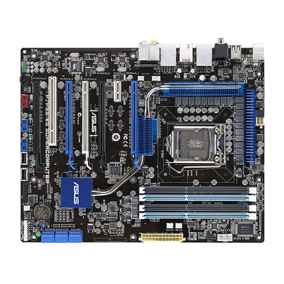
Motherboard overview 2.2.1 Motherboard layout Chapter 2: Hardware information... -
Page 27: Layout Contents
2-28 Digital audio connector (4-1 pin SPDIF_OUT) Optical drive audio connector (4-pin CD) 2-29 2-29 Front panel audio connector (10-1 pin AAFP) Refer to 2.7 Connectors for more information about rear panel connectors and internal connectors. ASUS P7P55 WS Supercomputer... -
Page 28: Placement Direction
2.2.3 Placement direction When installing the motherboard, ensure that you place it into the chassis in the correct orientation. The edge with external ports goes to the rear part of the chassis as indicated in the image below. 2.2.4 Screw holes Place nine (9) screws into the holes indicated by circles to secure the motherboard to the chassis. -
Page 29: Central Processing Unit (Cpu)
ASUS will shoulder the cost of repair only if the damage is shipment/transit-related. • Keep the cap after installing the motherboard. ASUS will process Return Merchandise Authorization (RMA) requests only if the motherboard comes with the cap on the LGA1156 socket. -
Page 30: Installing The Cpu
2.3.1 Installing the CPU To install a CPU: Locate the CPU socket on the motherboard. Press the load lever with your Load lever thumb (A), and then move it to the right (B) until it is released from the retention tab. To prevent damage to the socket pins, do not remove the PnP cap Retention tab... - Page 31 If so, skip this step. The Thermal Interface Material is toxic and inedible. DO NOT eat it. If it gets into your eyes or touches your skin, wash it off immediately, and seek professional medical help. ASUS P7P55 WS Supercomputer...
- Page 32 Close the load plate (A), and then push down the load lever (B), ensuring that the front edge of the load plate slides under the retention knob (C). Insert the load lever under the retention tab. Chapter 2: Hardware information...
-
Page 33: Installing The Cpu Heatsink And Fan
Push down two fasteners at a time in a diagonal sequence to secure the heatsink and fan assembly in place. Orient the heatsink and fan assembly such that the CPU fan cable is closest to the CPU fan connector. ASUS P7P55 WS Supercomputer... -
Page 34: Uninstalling The Cpu Heatsink And Fan
Connect the CPU fan cable to the connector on the motherboard labeled CPU_FAN. DO NOT forget to connect the CPU fan connector! Hardware monitoring errors can occur if you fail to plug this connector. 2.3.3 Uninstalling the CPU heatsink and fan To uninstall the CPU heatsink and fan: Disconnect the CPU fan cable from the connector on the motherboard. -
Page 35: System Memory
The figure illustrates the location of the DDR3 DIMM sockets: Recommended memory configurations One DIMM: Install one memory module in DIMM_A1 slots as a single-channel operation. Two DIMMs (dual-channel operation): Four DIMMs (dual-channel operation): ASUS P7P55 WS Supercomputer 2-11... -
Page 36: Memory Configurations
2.4.2 Memory configurations You may install 1GB, 2GB and 4GB non-ECC unbuffered DDR3 DIMMs into the DIMM sockets. • You may install varying memory sizes in Channel A and Channel B. The system maps the total size of the lower�sized channel for the dual�channel configuration. - Page 37 P7P55 WS Supercomputer Motherboard Qualified Vendors Lists (QVL) DDR��21��MH�� capability 3-2133MHz capability -2133MHz capability Vendor Part No. Size Chip NO. Timing Voltage DIMM socket Lable(Bios) support (Optional) G.SKILL F3-17066CL9T-6GB-T 6144MB(Kit of 3) DS Heat-Sink Package 9-9-9-24(1066-8-7-7-20) 1.65 • P7P55 WS Supercomputer Motherboard Qualified Vendors Lists (QVL) DDR��1866MH��...
- Page 38 P7P55 WS Supercomputer Motherboard Qualified Vendors Lists (QVL) DDR��16��MH�� capability 3-1600MHz capability -1600MHz capability Vendor Part No. Size Chip Brand Chip NO. Timing Voltage DIMM socket Lable(Bios) support (Optional) B* C* A-DATA AD31600E001GMU 3072MB(Kit of 3) Heat-Sink Package 8-8-8-24(1333- 1.65- •...
- Page 39 P7P55 WS Supercomputer Motherboard Qualified Vendors Lists (QVL) DDR��1���MH�� capability 3-1333MHz capability -1333MHz capability Vendor Part No. Size Chip Brand Chip NO. Timing Voltage DIMM socket Lable(Bios) support (Optional) A-DATA AD133301GOU 1024MB A-DATA AD30908C8D-15IG (1333-9-9-9-24) • • • A-DATA AD1333002GOU...
-
Page 40: Memory Configuration
• C*: Supports four modules inserted into both the blue and black slots as two pairs of dual�channel memory configuration. Visit the ASUS website at www.asus.com for the latest QVL. 2-16 Chapter 2: Hardware information... -
Page 41: Installing A Dimm
Press the retaining clip outward to unlock the DIMM. Support the DIMM lightly with your fingers when pressing the retaining clips. The DIMM might get damaged when it flips out with extra force. Remove the DIMM from the socket. ASUS P7P55 WS Supercomputer 2-17... -
Page 42: Expansion Slots
Expansion slots In the future, you may need to install expansion cards. The following sub-sections describe the slots and the expansion cards that they support. Ensure to unplug the power cord before adding or removing expansion cards. Failure to do so may cause you physical injury and damage motherboard components. -
Page 43: Interrupt Assignments
PCI slot The PCI slot supports cards such as a LAN card, SCSI card, USB card, and other cards that comply with PCI specifications. Refer to the figure below for the location of the slot. ASUS P7P55 WS Supercomputer 2-19... -
Page 44: Pci Express X1 Slot
2.5.5 PCI Express x1 slot This motherboard supports PCI Express x1 network cards, SCSI cards and other cards that comply with the PCI Express specifications. Install a PCIe x1 device to a PCIe x1 slot prior to a PCIe x16 slot. 2.5.6 PCI Express 2.0 x16 slots This motherboard has four PCI Express 2.0 slots, two x8 link and two x8 or x16... -
Page 45: Jumper
• Due to the chipset behavior, AC power off is required to enable C.P.R. function. You must turn off and on the power supply or unplug and plug the power cord before rebooting the system. ASUS P7P55 WS Supercomputer 2-21... -
Page 46: Connectors
Connectors 2.7.1 Rear panel connectors Rear panel connectors 1. PS/2 mouse port (green) 7. USB 2.0 ports 13 and 14 2. Coaxial S/PDIF Out port 8. Optical S/PDIF Out port 3. LAN (RJ-45) port** 9. USB 2.0 ports 5 and 6 4. -
Page 47: Audio I/O Connections
Orange – – Center/Subwoofer Center/Subwoofer Black – Rear Speaker Out Rear Speaker Out Rear Speaker Out Gray – – – Side Speaker Out 2.7.2 Audio I/O connections Audio I/O ports Connect to Headphone and Mic ASUS P7P55 WS Supercomputer 2-23... - Page 48 Connect to Stereo Speakers Connect to 2.1 channel Speakers Connect to 4.1 channel Speakers 2-24 Chapter 2: Hardware information...
- Page 49 Connect to 5.1 channel Speakers Connect to 7.1 channel Speakers ASUS P7P55 WS Supercomputer 2-25...
-
Page 50: Internal Connectors
2.7.3 Internal connectors Serial ATA connectors (7-pin SATA 1-6 [blue]) These connectors are for the Serial ATA signal cables for Serial ATA hard disk drives and optical disc drives. If you installed Serial ATA hard disk drives, you can create a RAID 0, 1, 5, and 1�... - Page 51 Never connect a 1394 cable to the USB connectors. Doing so will damage the motherboard! You can connect the USB cable to ASUS Q�Connector (USB, blue) first, and then install the Q-Connector (USB) to the USB connector onboard. The USB cable is purchased separately.
- Page 52 IEEE 1394a port connector (10-1 pin IE1394_2) This connector is for an IEEE 1394a port. Connect the IEEE 1394a module cable to this connector, then install the module to a slot opening at the back of the system chassis. Never connect a USB cable to the IEEE 1394a connector. Doing so will damage the motherboard! The IEEE 1394a cable is purchased separately.
- Page 53 Front Panel Type item in the BIOS setup to [HD Audio]; if you want to connect an AC'97 front panel audio module to this connector, set the item to [AC97]. By default, this connector is set to [HD Audio]. ASUS P7P55 WS Supercomputer 2-29...
- Page 54 A TPM system also helps enhance network security, protects digital identities, and ensures platform integrity. The TPM module is purchased separately. Use the ASUS TPM module ONLY! 2-30 Chapter 2: Hardware information...
- Page 55 • If you are uncertain about the minimum power supply requirement for your system, refer to the Recommended Power Supply Wattage Calculator at http://support.asus.com/PowerSupplyCalculator/PSCalculator. aspx?SLanguage=en-us for details. ASUS P7P55 WS Supercomputer 2-31...
-
Page 56: System Panel Connector
11. System panel connector (20-8 pin PANEL) This connector supports several chassis-mounted functions. • System power LED (2-pin PLED) This 2-pin connector is for the system power LED. Connect the chassis power LED cable to this connector. The system power LED lights up when you turn on the system power, and blinks when the system is in sleep mode. -
Page 57: Asus Q-Connector
12. ASUS Q-Connector (system panel) Use the ASUS Q-Connector to connect/disconnect the chassis front panel cables. To install the ASUS Q-Connector: Connect the front panel cables to the ASUS Q-Connector. Refer to the labels on the Q- Connector to know the detailed pin... -
Page 58: Onboard Switches
DIAG_DRAM LED lights continuously. Replace the DIMMs with ones recommended in the Memory QVL (Qualified Vendors Lists) in this user manual or on the ASUS website at www.asus.com. • If you turn off the computer and replace DIMMs during the tuning process, the system continues memory tuning after turning on the computer. - Page 59 According to Intel CPU spec, DIMMs voltage below 1.65V is recommended to protect the CPU. • The system may need a better cooling system (for example, a water-cooling system) to work stably under high voltage settings. ASUS P7P55 WS Supercomputer 2-35...
-
Page 60: Onboard Leds
Onboard LEDs POST State LEDs POST State LEDs check key components (CPU, DRAM, VGA card, and HDD) in sequence during motherboard booting process. If an error is found, the LED next to the error device will continue lighting until the problem is solved. -
Page 61: Starting Up For The First Time
No VGA detected short beeps One continuous beep followed by four Hardware component failure short beeps At power on, hold down the <Delete> key to enter the BIOS Setup. Follow the instructions in Chapter 3. ASUS P7P55 WS Supercomputer 2-37... -
Page 62: 2.10 Turning Off The Computer
2.10 Turning off the computer 2.10.1 Using the OS shut down function If you are using Windows Vista™: ® Click the Start button then select Shut Down. The power supply should turn off after Windows shuts down. ® If you are using Windows ®... -
Page 63: Chapter 3: Bios Setup
This chapter tells how to change the system settings through the BIOS Setup menus. Detailed descriptions of the BIOS parameters are also provided. BIOS setup... - Page 64 BIOS setup program ..............3-6 Main menu .................. 3-10 Extreme Tweaker menu Extreme Tweaker menu menu ............. 3-15 Advanced menu ................. 3-22 Power menu ................3-29 Boot menu .................. 3-34 Tools menu ................. 3-38 Exit menu ..................3-42 ASUS P7P55 WS Supercomputer...
-
Page 65: Managing And Updating Your Bios
BIOS in the future. Copy the original motherboard BIOS using the ASUS Update utility. 3.1.1 ASUS Update utility The ASUS Update is a utility that allows you to manage, save, and update the motherboard BIOS in Windows environment. The ASUS Update utility allows you to: ®... - Page 66 To update the BIOS through the Internet: Launch the ASUS Update utility from the Windows desktop by clicking Start ® > Programs > ASUS > ASUSUpdate > ASUSUpdate. The ASUS Update main window appears. Select Update BIOS from the Select the ASUS FTP site nearest...
- Page 67 To update the BIOS through a BIOS file: desktop by clicking Start Launch the ASUS Update utility from the Windows ® > Programs > ASUS > ASUSUpdate > ASUSUpdate. The ASUS Update main window appears. Select Update BIOS from a file option from the drop-down menu, then click Next.
-
Page 68: Asus Ez Flash 2 Utility
3.1.2 ASUS EZ Flash 2 utility The ASUS EZ Flash 2 feature allows you to update the BIOS without having to use a DOS-based utility. The EZ Flash 2 utility is built in the BIOS chip so it is accessible by pressing <Alt> + <F2> during the Power-On Self Tests (POST). -
Page 69: Bupdater Utility
Updating the BIOS file To update the BIOS file using the BUPDATER utility: Visit the ASUS website at www.asus.com and download the latest BIOS file for the motherboard. Save the BIOS file to a bootable USB flash disk drive. USB flash disk drive. . -
Page 70: Asus Crashfree Bios 3 Utility
3.1.4 ASUS CrashFree BIOS 3 utility The ASUS CrashFree BIOS 3 utility is an auto recovery tool that allows you to restore the BIOS file when it fails or gets corrupted during the updating process. You can restore a corrupted BIOS file using the motherboard support DVD or a USB flash drive that contains the BIOS file. -
Page 71: Bios Setup Program
The BIOS setup screens shown in this section are for reference purposes only, and may not exactly match what you see on your screen. • Visit the ASUS website at www.asus.com to download the latest BIOS file for this motherboard. ASUS P7P55 WS Supercomputer... -
Page 72: Bios Menu Screen
3.2.1 BIOS menu screen Menu bar Menu items Configuration fields General help BIOS SETUP UTILITY Main Ai Tweaker Advanced Power Boot Tools Exit Use [ENTER], [TAB] System Time [13:51:25] or [SHIFT-TAB] to System Date [THU 06/18/2009] select a field. Language [English] Use [+] or [-] to SATA1 [HDT722516DLA380] configure system Date. SATA2 [Not Detected] SATA3 [ATAPI DVD D DH1] SATA4 [Not Detected] SATA5 [Not Detected] SATA6 [Not Detected] ←→ Select Screen Storage Configuration... -
Page 73: Menu Items
Up/Down arrow keys or <Page Up> / <Page Down> keys to display the other items on the screen. 3.2.9 General help At the top right corner of the menu screen is a brief description of the selected item. ASUS P7P55 WS Supercomputer... -
Page 74: Main Menu
Main menu When you enter the BIOS Setup program, the Main menu screen appears, giving you an overview of the basic system information. Refer to section 3.2.1 BIOS menu screen for information on the menu screen items and how to navigate through them. BIOS SETUP UTILITY Main AI Tweaker Advanced Power Boot Tools Exit Use [ENTER], [TAB]... -
Page 75: Sata 1-6
Enables or disables the LBA (Logical Block Addressing) mode. [Auto] Select [Auto] to enable the LBA mode (Logical Block Addressing mode) if the device supports this mode, and if the device was not previously formatted with LBA mode disabled. [Disabled] Disables this function. ASUS P7P55 WS Supercomputer 3-11... - Page 76 Block (Multi-Sector Transfer) M [Auto] Enables or disables data multi-sectors transfers. [Auto] When set to [Auto], the data transfer from and to the device occurs in multiple sectors at a time if the device supports multi-sector transfer feature. [Disabled] When set to [Disabled], the data transfer from and to the device occurs one sector at a time.
-
Page 77: Storage Configuration
Disables or enables device write protection. This will be effective only if the device is accessed through BIOS. Configuration option: [Disabled] [Enabled] IDE Detect Time Out (Sec) [35] Selects the time out value for detecting ATA/ATAPI devices. Configuration options: [0] [5] [10] [15] [20] [25] [30] [35] ASUS P7P55 WS Supercomputer 3-13... -
Page 78: Ahci Configuration
�.�.6 AHCI Configuration This menu is the section for AHCI configuration. It appears only when you set the item Configure SATA as from the sub-menu of SATA Configuration to [AHCI]. BIOS SETUP UTILITY Main AHCI Settings Some SATA CD/DVD in AHCI mode need to wait ready longer. SATA Port1 [Not Detected] SATA Port2 [Not Detected] SATA Port3 [Not Detected] SATA Port4 [Not Detected] SATA Port5 [Not Detected] SATA Port6 [Not Detected] SATA Port1–6 [XXXX]... -
Page 79: Ai Tweaker Menu
[ 1.048V] IMC Voltage [Auto] Current IMC Voltage [ 1.109V] DRAM Voltage [Auto] Current DRAM Voltage [ 1.500V] CPU PLL Voltage [Auto] Current CPU PLL Voltage [ 1.800V] PCH Voltage [Auto] Current PCH Voltage [ 1.040V] DRAM DATA REF Voltage on CHA [Auto] DRAM CTRL REF Voltage on CHA [Auto] ←→ Select Screen DRAM DATA REF Voltage on CHB [Auto] ↑↓ Select Item DRAM CTRL REF Voltage on CHB [Auto] +- Change Option *********************************************** F1 General Help Load-Line Calibration [Auto] F10 Save and Exit CPU Spread Spectrum [Auto] ESC Exit PCIE Spread Spectrum [Auto] v02.61 (C)Copyright 1985-2009, American Megatrends, Inc. ASUS P7P55 WS Supercomputer 3-15... -
Page 80: Ai Overclock Tuner [Auto]
3.4.1 Ai Overclock Tuner [Auto] Allows selection of CPU overclocking options to achieve desired CPU internal frequency. Select either one of the preset overclocking configuration options: Manual Allows you to individually set overclocking parameters. Auto Loads the optimal settings for the system. D.O.C.P Overclocks DRAM frequency by adjusting BCLK frequency. -
Page 81: Intel(R) Turbomode Tech [Enabled]
Press the <ENTER> key to start automatic system overclocking. The OC Tuner Utility automatically adjust system parameters and reboots several times for the best overclocking result. DO NOT shut down the power before the auto-adjustment completes. ASUS P7P55 WS Supercomputer 3-17... -
Page 82: Oc Tuner Limit Value [Good Performance]
3.4.9 OC Tuner limit Value [Good Performance] Set an auto-adjustment limit value for OC Tuner Utility. Configuration options: [Good Performance] [Better Performance] 3.4.10 DRAM Timing Control [Auto] The items in this menu allow you to set the DRAM timing control features. The configuration options for some of the following items vary depending on the depending on the DIMMs you install on the motherboard. - Page 83 Configuration options: [Auto] [2 DRAM Clock] – [9 DRAM Clock] DRAM WRITE to WRITE Delay(DR) [Auto] Configuration options: [Auto] [2 DRAM Clock] – [9 DRAM Clock] DRAM WRITE to WRITE Delay(SR) [Auto] Configuration options: [Auto] [4 DRAM Clock] [6 DRAM Clock] ASUS P7P55 WS Supercomputer 3-19...
-
Page 84: Cpu Differential Amplitude [Auto]
3.4.11 CPU Differential Amplitude [Auto] Different AMP might enhance BCLK overclocking ability. Configuration options: [Auto] [7��mV] [8��mV] [9��mV] [1���mV] 3.4.12 CPU Clock Skew [Auto] Adjusting this item may help enhancing BCLK overclocking ability. You may need to adjust the NB Clock Skew item at the same time. Configuration options: [Auto] [Normal] [Delay 1��ps]–[Delay 15��ps] The following ten (10) items are adjusted by typing the desired values using the numeric keypad and press the <Enter>... -
Page 85: Dram Voltage [Auto]
Automatic configuration. [Disabled] Enhances the BCLK overclocking ability. [Enabled] Sets to [Enabled] for EMI control. 3.4.22 PCIE Spread Spectrum [Auto] [Auto] Automatic configuration. [Disabled] Enhances the PCIE overclocking ability. [Enabled] Sets to [Enabled] for EMI control. ASUS P7P55 WS Supercomputer 3-21... -
Page 86: Advanced Menu
Advanced menu The Advanced menu items allow you to change the settings for the CPU and other system devices. BIOS SETUP UTILITY Main Ai Tweaker Advanced Power Boot Tools Exit Configure CPU. CPU Configuration Uncore Configuration Onboard Devices Configuration USB Configuration PCIPnP Intel VT-d [Disabled] T.Probe [Disabled] ←→ Select Screen ↑↓ Select Item Enter Go to Sub Screen F1 General Help F10 Save and Exit ESC Exit... - Page 87 CPUs with extended CPUID functions. [Disabled] Disables this function. Intel(R) Virtualization Tech [Enabled] [Enabled] Allows a hardware platform to run multiple operating systems separately and simultaneously, enabling one system to virtually function as several systems. [Disabled] Disables this function. ASUS P7P55 WS Supercomputer 3-23...
- Page 88 CPU TM function [Enabled] [Enabled] Enables the overheated CPU to throttle its clock speed to cool down. [Disabled] Disables this function. Execute Disable Bit Capability [Enabled] [Enabled] Enables the No-Execution Page Protection Technology. [Disabled] Forces the XD feature flag to always return to zero (�). Intel(R) HT Technology [Enabled] [Enabled] Enables the Intel Hyper-Threading Technology.
-
Page 89: North Bridge Configuration
Set the front panel audio connector (AAFP) mode to legacy AC’97. [HD Audio] Set the front panel audio connector (AAFP) mode to high- definition audio. SPDIF OUT Mode Setting [SPDIF] [SPDIF] Select SPDIF mode. [HDMI] Select HDMI mode. ASUS P7P55 WS Supercomputer 3-25... - Page 90 Realtek LAN1/2 [Enabled] [Enabled] Enables Realtek LAN Controller 1/2. [Disabled] Disables Realtek LAN Controller 1/2. LAN Boot ROM [Disabled] This item appears only when you enable the previous item(s). [Disabled] Disables Realtek LAN Boot ROM. [Enabled] Enables Realtek LAN Boot ROM. Onboard 1394 Controller [Enabled] [Enabled] Enables the onboard 1394 Controller.
-
Page 91: Usb Configuration
Enables the support for USB devices on legacy operating systems (OS). [Disabled] Disables the function. BIOS EHCI Hand-off [Enabled] [Enabled] Enables the support for operating systems without an EHCI hand-off feature. [Disabled] Disables the function. ASUS P7P55 WS Supercomputer 3-27... -
Page 92: Pcipnp
3.5.5 PCIPnP The PCIPnP menu items allow you to change the advanced settings for PCI/PnP devices. Take caution when changing the settings of the PCI PnP menu items. Incorrect field values can cause the system to malfunction. BIOS SETUP UTILITY Advanced Advanced PCI/PnP Settings NO: lets the BIOS configure all the WARNING: Setting wrong values in below sections... -
Page 93: Power Menu
ACPI 2.0 Support [Disabled] [Disabled] When set to [Disabled], the system will not add additional tables as per ACPI 2.� specifications. [Enabled] When set to [Enabled], the system adds additional tables as per ACPI 2.� specifications. ASUS P7P55 WS Supercomputer 3-29... -
Page 94: Apm Configuration
3.6.4 ACPI APIC Support [Enabled] Allows you to enable or disable the Advanced Configuration and Power Interface (ACPI) support in the Advanced Programmable Interrupt Controller (APIC). [Disabled] When set to [Disabled], the system disable the Advanced Configuration and Power Interface (ACPI) support in the Advanced Programmable Interrupt Controller (APIC). - Page 95 Power On By PS/2 Mouse [Disabled] [Disabled] Disables the Power On by a PS/2 mouse. [Enabled] Enables the Power On by a PS/2 mouse. This feature requires an ATX power supply that provides at least 1A on the +5VSB lead. ASUS P7P55 WS Supercomputer 3-31...
-
Page 96: Hardware Monitor
3.6.7 Hardware Monitor BIOS SETUP UTILITY Power Hardware Monitor Voltage Monitor CPU Temperature [35ºC/95ºF] MB Temperature [34ºC/93ºF] CPU Fan Speed [3590RPM] CPU Q-Fan Control [Disabled] Chassis Fan 1 Speed [N/A] Chassis Fan 2 Speed [N/A] Chassis Fan 3 Speed [N/A] Chassis Q-Fan Control [Disabled] ←→ Select Screen Power Fan Speed [N/A] ↑↓ Select Item F1 General Help CPU Voltage [ 1.040V] F10 Save and Exit 3.3V Voltage [ 3.008V] ESC Exit 5V Voltage [ 4.776V] 12V Voltage [11.648V] v02.61 (C)Copyright 1985-2009, American Megatrends, Inc. CPU/MB Temperature [xxx�C/xxx�F] [xxx�C/xxx�F] The onboard hardware monitor automatically detects and displays the CPU and motherboard temperatures. - Page 97 Set to [Turbo] to achieve maximum chassis fan speed. CPU Voltage, 3.3V Voltage, 5V Voltage, 12V Voltage The onboard hardware monitor automatically detects the voltage output through the onboard voltage regulators. Select Ignored if you do not want to detect this item. ASUS P7P55 WS Supercomputer 3-33...
-
Page 98: Boot Menu
Boot menu The Boot menu items allow you to change the system boot options. Select an item then press <Enter> to display the sub-menu. BIOS SETUP UTILITY Main Ai Tweaker Advanced Power Boot Tools Exit Specifies the Boot Boot Settings Device Priority sequence. Boot Device Priority A virtual floppy disk Boot Settings Configuration drive (Floppy Drive B: Security ) may appear when you... -
Page 99: Boot Settings Configuration
Enables the full screen logo display feature. [Disabled] Disables the full screen logo display feature. Set this item to [Enabled] to use the ASUS MyLogo3™ feature. AddOn ROM Display Mode [Force BIOS] Sets the display mode for option ROM. [Force BIOS] [Keep Current] . -
Page 100: Security
POST State LEDs [Enabled] [Enabled] Turn on onboard device LEDs in the order of the device POST sequence. [Disabled] Disables this function. 3.7.4 Security The Security menu items allow you to change the system security settings. Select an item then press <Enter> to display the configuration options. BIOS SETUP UTILITY Boot <Enter> to change... -
Page 101: Change User Password
When set to [Setup], BIOS checks for user password when accessing the Setup utility. When set to [Always], BIOS checks for user password both when accessing Setup and booting the system. Configuration options: [Setup] [Always] ASUS P7P55 WS Supercomputer 3-37... -
Page 102: Tools Menu
Tools menu The Tools menu items allow you to configure options for special functions. Select an item then press <Enter> to display the sub-menu. BIOS SETUP UTILITY Main Ai Tweaker Advanced Power Boot Tools Exit ASUS O.C. Profile AI NET 2 ASUS EZ Flash 2 Express Gate [Auto] Enter OS Timer [10 Seconds] Reset User Data [No] ←→ Select Screen ↑↓ Select Item Enter Go to Sub Screen... -
Page 103: Ai Net 2
AI NET 2 BIOS SETUP UTILITY Tools Ai Net 2 Check Realtek LAN Pair Status Length cable during POST. It will take 3 to 10 seconds to diagnose Check Realtek LAN cable [Disabled] LAN cable. Check Realtek LAN cable [Disabled] Enables or disables checking of the LAN cable during the Power-On Self-Test (POST). Configuration options: [Disabled] [Enabled] ASUS P7P55 WS Supercomputer 3-39... -
Page 104: Asus Ez Flash 2
3.8.3 ASUS EZ Flash 2 Allows you to run ASUS EZ Flash 2. When you press <Enter>, a confirmation message appears. Use the left/right arrow key to select between [Yes] or [No], then press <Enter> to confirm your choice. For more details, refer to section 3.1.2 ASUS EZ Flash 2 utility. - Page 105 Gate environment from launching properly. [No] Set to [No] to disable the Reset User Data function when entering the Express Gate. The first time wizard will run again when you enter the Express Gate environment after clearing its settings. ASUS P7P55 WS Supercomputer 3-41...
-
Page 106: Exit Menu
Exit menu The Exit menu items allow you to load the optimal or failsafe default values for the BIOS items, and save or discard your changes to the BIOS items. BIOS SETUP UTILITY Main Ai Tweaker Advanced Power Boot Tools Exit Exit system setup after Exit Options saving the changes. F10 key can be used for Exit & Save Changes this operation. Exit & Discard Changes Discard Changes Load Setup Defaults ←→ Select Screen ↑↓ Select Item... -
Page 107: Chapter 4: Software Support
This chapter describes the contents of the support DVD that comes with the motherboard package and the software. Software support... - Page 108 Chapter summary Installing an operating system ........... 4-1 Support DVD information ............4-1 Software information ..............4-9 ASUS Unique Overclocking Utility—TurboV EVO ....4-21 RAID configurations ..............4-25 Creating a RAID driver disk ............4-30 ASUS P7P55 WS Supercomputer...
-
Page 109: Installing An Operating System
The contents of the support DVD are subject to change at any time without notice. Visit the ASUS website at www.asus.com for updates. 4.2.1 Running the support DVD Place the support DVD to the optical drive. -
Page 110: Drivers Menu
Realtek LAN Driver Installs the Realtek Gigabit Ethernet Driver. ® ASUS TurboV EVO Installs ASUS TurboV EVO, the advanced overclocking tool for extreme O.C. record. ASUS EPU-6 Engine Installs ASUS EPU-6 Engine driver and utility. ASUS Express Gate Installer Installs ASUS Express Gate. -
Page 111: Utilities Menu
The Utilities menu shows the applications and other software that the motherboard supports. ASUS Update The ASUS Update utility allows you to update the motherboard BIOS in Windows ® environment. This utility requires an Internet connection either through a network or an Internet Service Provider (ISP). -
Page 112: Make Disk Menu
4.2.4 Make disk menu The Make disk menu contains items to create the Intel RAID driver disk. Intel AHCI/RAID Driver Allows you to create an AHCI/RAID Driver disk. 4.2.5 Manual menu The Manuals menu contains a list of supplementary user manuals. Click an item to open the folder of the user manual. -
Page 113: Asus Contact Information
4.2.6 ASUS Contact information Click the Contact tab to display the ASUS contact information. You can also find this information on the inside front cover of this user guide. ASUS P7P55 WS Supercomputer... -
Page 114: Other Information
4.2.7 Other information The icons on the top right corner of the screen give additional information on the motherboard and the contents of the support DVD. Click an icon to display the specified information. Motherboard Info Displays the general specifications of the motherboard. Browse this DVD Displays the support DVD contents in graphical format. - Page 115 Filelist Displays the contents of the support DVD and a brief description of each in text format. ASUS P7P55 WS Supercomputer...
-
Page 116: Software Information
To launch the PC Probe II from the Windows ® > ASUS > PC Probe II > PC Probe II v1.xx.xx. The PC Probe II main window appears. After launching the application, the PC Probe II icon appears in the Windows ®... - Page 117 When displayed, the monitor panel for that sensor also turns red. Refer to the Monitor panels section for details. Preferences You can customize the application using the Preference section in the main window. Click the box before each preference to activate or deactivate. ASUS P7P55 WS Supercomputer...
- Page 118 Hardware monitor panels The hardware monitor panels display the current value of a system sensor such as fan rotation, CPU temperature, and voltages. The hardware monitor panels come in two display modes: hexagonal (large) and rectangular (small). When you check the Enable Monitoring Panel option from the Preference section, the monitor panels appear on your computer’s desktop.
- Page 119 DMI browser Click to display the DMI (Desktop Management Interface) browser. This browser displays various desktop and system information. Click the plus sign (+) before DMI Information to display the available information. ASUS P7P55 WS Supercomputer 4-11...
- Page 120 PCI browser Click to display the PCI (Peripheral Component Interconnect) browser. This browser provides information on the PCI devices installed on your system. Click the plus sign (+) before the PCI Information item to display available information. Usage The Usage browser displays real-time information on the CPU, hard disk drive space, and memory usage.
- Page 121 The Preference tab allows you to customize sensor alerts, or change the temperature scale. Loads the default Loads your saved threshold values for Cancels or configuration each sensor ignores your changes Applies your Saves your changes configuration ASUS P7P55 WS Supercomputer 4-13...
-
Page 122: Asus Ai Suite
Start > All Programs > To launch AI Suite from the Windows ® ASUS > AI Suite > AI Suite v1.xx.xx. The AI Suite main window appears. After launching the application, the AI Suite icon appears in the Windows ®... - Page 123 Displays the CPU/ system temperature, CPU/memory/PCIE voltage, and CPU/ chassis fan speed Displays the FSB/CPU frequency Click on right corner of the expanded window to switch the temperature from degrees Centigrade to degrees Fahrenheit. ASUS P7P55 WS Supercomputer 4-15...
-
Page 124: Asus Fan Xpert
4.3.3 ASUS Fan Xpert Asus Fan Xpert allows you to adjust both the CPU and chassis fan speeds according to different ambient temperatures and your PC’s system loading. The various fan profiles offer flexible controls of fan speeds to achieve a quiet and cool system environment. -
Page 125: Asus Epu-6 Engine
4.3.4 ASUS EPU-6 Engine ASUS EPU�6 Engine is an energy�efficient tool that satisfies different computing needs. This utility provides four modes that you can select to enhance system performance or save power: • Medium Power Saving Mode Turbo Mode •... -
Page 126: Asus Express Gate
4.3.5 ASUS Express Gate ASUS Express Gate is an instant-on environment that gives you quick access to the Internet, Skype, and viewing your pictures. Within a few seconds of powering on your computer, you will be at the Express Gate menu where you can start the web browser, Skype, or other Express Gate applications. - Page 127 See the software manual in the bundled motherboard support DVD or click in the Express Gate environment for detailed software instructions. • Express Gate complies with the OpenGL standard. Refer to http://support. asus.com for Express Gate source codes. ASUS P7P55 WS Supercomputer 4-19...
-
Page 128: Asus T.probe
Follow the screen instructions to complete installation. Before using ASUS T.Probe You have to configure BIOS settings before using ASUS T.Probe. Press <Del> during the Power-On Self Test (POST) to enter the Setup utility. Set the T.Probe item in the Advanced menu to [Enabled] Save BIOS settings and restart the computer. -
Page 129: Asus Unique Overclocking Utility-Turbov Evo
If the TurboV EVO is correctly installed, you will find the TurboV EVO icon on the Windows notification area. Click on the icon to display the TurboV EVO control panel. Refer to the software manual in the support DVD or visit the ASUS website at www.asus.com for detailed software configuration. 4.4.1... -
Page 130: Using Asus Turbov Auto Tuning Mode
For advanced overclock ability, adjust first the BIOS items, and then proceed more detailed adjustments using TurboV. 4.4.2 Using ASUS TurboV Auto Tuning Mode The Auto Tuning Mode allows smart auto-overclocking. Follow the instructions below to let TurboV EVO detect and overclock your system. -
Page 131: Using Asus Turbo Key
Using ASUS Turbo Key ASUS Turbo Key allows the user to set a group of hot-keys into physical overclocking buttons. After the easy setup, Turbo Key can boost performances without interrupting ongoing work or games—with just one touch! If the TurboV EVO is correctly installed, you will find the TurboV EVO icon on the Windows notification area. - Page 132 Select your desired hotkey combination. You can decide the performance boost level by selecting Turbo Key Profile. You can also load personal profiles saved in the ASUS TurboV utility. Choose whether to show Turbo Key OSD and status. Click Apply to save Turbo Key settings.
-
Page 133: Raid Configurations
RAID sets to get higher performance, capacity, or fault tolerance provided by the difference RAID function. For example, RAID 0 and RAID 1 set can be created by using only two identical hard disk drives. ASUS P7P55 WS Supercomputer 4-25... -
Page 134: Installing Serial Ata Hard Disks
4.5.2 Installing Serial ATA hard disks The motherboard supports Serial ATA hard disk drives. For optimal performance, install identical drives of the same model and capacity when creating a disk array. To install the SATA hard disks for a RAID configuration: Install the SATA hard disks into the drive bays. -
Page 135: Creating A Raid Volume
When the Disks item is selected, press <Enter> to select the hard disk drives you want to include in the RAID set. The SELECT DISKS screen appears. [ SELECT DISKS ] Port Drive Model Serial # Size Status 0 ST3160812AS 9LS0HJA4 149.0GB Non-RAID Disk 1 ST3160812AS 9LS0F4HL 149.0GB Non-RAID Disk 2 ST3160812AS 3LS0JYL8 149.0GB Non-RAID Disk 3 ST3160812AS 9LS0BJ5H 149.0GB Non-RAID Disk Select 2 to 6 disks to use in creating the volume. [ ↑↓ ]-Prev/Next [SPACE]-SelectDisk [ENTER]-Done ASUS P7P55 WS Supercomputer 4-27... - Page 136 Use the up/down arrow key to select a drive, and then press <Space> to select. A small triangle marks the selected drive. Press <Enter> after completing your selection. Use the up/down arrow key to select the stripe size for the RAID array (for RAID �, 1�...
-
Page 137: Deleting A Raid Set
To exit the utility From the utility main menu, select 5. Exit, and then press <Enter>. The following warning message appears. [ CONFIRM EXIT ] Are you sure you want to exit? (Y/N): Press <Y> to exit or press <N> to return to the utility main menu. ASUS P7P55 WS Supercomputer 4-29... -
Page 138: Creating A Raid Driver Disk
Creating a RAID driver disk A floppy disk with the RAID driver is required when installing Windows ® operating system on a hard disk drive that is included in a RAID set. For Windows ® Vista or later operating systems, use either a floppy disk or a USB flash drive with the RAID driver. -
Page 139: Installing The Raid Driver During Windows ® Os Installation
Select Device Manager. From the Universal Serial Bus controllers, right-click xxxxxx USB Floppy, and then select Properties from the pop- up window. The name of the USB floppy disk drive varies with different vendors. ASUS P7P55 WS Supercomputer 4-31... - Page 140 Click Details tab. The Vendor ID (VID) and Product ID (PID) are displayed. Browse the contents of the RAID driver disk to locate the file txtsetup.oem. Double�click the file. A window appears, allowing you to select the program for opening the oem file. Use Notepad to open the file.
- Page 141 Type the following line to the bottom of the two sections: id = “USB\VID_xxxx&PID_xxxx”, “usbstor” [HardwareIds.scsi.iaAHCI_PCH] id= “PCI\VEN_8086&DEV_3A22&CC_0106”,”iaStor” id= “USB\VID_03EE&PID_6901”, “usbstor” [HardwareIds.scsi.iaStor_8R9R10RDOPCH] id= “PCI\VEN_8086&DEV_3A22&CC_0106”,”iaStor” id= “USB\VID_03EE&PID_6901”, “usbstor” Add the same line to both sections. The VID and PID vary with different vendors. 1�. Save and exit the file. ASUS P7P55 WS Supercomputer 4-33...
- Page 142 4-34 Chapter 4: Software support...
-
Page 143: Chapter 5: Multiple Gpu Technology Support
This chapter describes how to install and configure multiple ATI CrossFireX™ and ® NVIDIA SLI™ graphics cards. ® Multiple GPU technology support... - Page 144 Chapter summary CrossFireX™ technology ............ 5-1 ® NVIDIA SLI™ technology ............5-5 ® NVIDIA CUDA™ technology ............ 5-11 ® ASUS P7P55 WS SuperComputer...
-
Page 145: Ati ® Crossfirex™ Technology
For Windows XP, go to Control Panel > Add/Remove Programs. For Windows Vista, go to Control Panel > Programs and Features. Select your current graphics card driver/s. For Windows XP, select Add/Remove. For Windows Vista, select Uninstall. Turn off your computer. ASUS P7P55 WS SuperComputer... -
Page 146: Installing Crossfirex Graphics Cards
5.1.3 Installing CrossFireX graphics cards The following pictures are for reference only. The graphics cards and the motherboard layout may vary with models, but the installation steps remain the same. Prepare two CrossFireX-ready graphics cards. Insert the two graphics card into the PCIEX16 slots. -
Page 147: Installing The Device Drivers
Windows notification area and select Cayalist Control Center. The Catalyst Control Center Setup Assistant appears when the system detects the existance of multi- graphics cards. Click Go to continue to the Catalyst Control Center Advanced View window. ASUS P7P55 WS SuperComputer... - Page 148 Enabling Dual CrossFireX settings In the Catalyst Control Center window, click Graphics Settings > CrossFireX > Configure. From the Graphics Adapter list, select the graphics card to act as the display GPU. Select Enable CrossFireX. Click Apply, and then click OK to exit the window.
-
Page 149: Nvidia ® Sli™ Technology
We recommend that you install additional chassis fans for better thermal environment. • The NVIDIA Triple SLI technology is supported by Windows Vista™ ® operating system only. • Visit the NVIDIA zone website at http://www.nzone.com for the latest certified graphics card and supported 3D application list. ASUS P7P55 WS SuperComputer... -
Page 150: Installing Two Sli-Ready Graphics Cards
5.2.2 Installing two SLI-ready graphics cards The following pictures are for reference only. The graphics cards and the motherboard layout may vary with models, but the installation steps remain the same. Prepare two SLI-ready graphics cards. Insert the two graphics card into the PCIEX16 slots. -
Page 151: Installing Three Sli-Ready Graphics Cards
Connect three independent auxiliary power sources from the power supply to the three graphics cards separately. Connect a VGA or a DVI cable to the graphics card. 3-Way SLI bridge ASUS P7P55 WS SuperComputer... -
Page 152: Installing The Device Drivers
5.2.4 Installing the device drivers Refer to the documentation that came with your graphics card package to install the device drivers. • Ensure that your PCI Express graphics card driver supports the ® NVIDIA SLI™ technology. Download the latest driver from the NVIDIA website at www.nvidia.com. - Page 153 B2. From the Personalization window, select Display Settings. B3. From the Display Settings dialog box, click Advanced Settings. B4. Select the NVIDIA GeForce tab, and then click Start the NVIDIA Control Panel. ASUS P7P55 WS SuperComputer...
- Page 154 B5. The NVIDIA Control Panel window appears. Enabling Dual SLI settings From the NVIDIA Control Panel window, select Set SLI Configuration. Click Enable SLI and set the display for viewing SLI rendered content. When done, click Apply. Enabling Triple SLI settings From the NVIDIA Control Panel window, select Set SLI Configuration, and then click Enable 3-way NVIDIA...
-
Page 155: Nvidia ® Cuda™ Technology
Prepare one NVIDIA Quadro graphics card and up to three NVIDIA Tesla computing processor cards. Insert the Quadro graphics card into the PCIe x16_1 slot. Ensure that the card is properly seated on the slot. ASUS P7P55 WS SuperComputer 5-11... - Page 156 Insert the Tesla computing processor card(s) into the PCIe x16_2, PCIe x16_4 or PCIe x16_5 slot. Ensure that the cards are properly seated on the slot. Connect either one 8-pin power connector or two 6-pin power connectors from the power supply to the Quadro graphics card and Tesla computing processor card(s).
Need help?
Do you have a question about the P7P55 WS SUPERCOMPUTER and is the answer not in the manual?
Questions and answers