Table of Contents
Advertisement
Advertisement
Table of Contents

Related Manuals for Asus P7H55-M


Summary of Contents for Asus P7H55-M
- Page 1 P7H55-M...
- Page 2 Product warranty or service will not be extended if: (1) the product is repaired, modified or altered, unless such repair, modification of alteration is authorized in writing by ASUS; or (2) the serial number of the product is defaced or missing.
-
Page 3: Table Of Contents
Contents Notices ......................vi Safety information ..................vii About this guide ..................vii P7H55-M specifications summary ............. ix Chapter 1: Product introduction Welcome! ..................1-1 Package contents ................. 1-1 Special features ................1-1 1.3.1 Product highlights ............1-1 1.3.2 Innovative ASUS features ..........1-3 Before you proceed .............. - Page 4 Chapter 2: BIOS information Managing and updating your BIOS ..........2-1 2.1.1 ASUS Update utility ............2-1 2.1.2 ASUS EZ Flash 2 ............2-2 2.1.3 ASUS CrashFree BIOS ........... 2-3 2.1.4 ASUS BIOS Updater ............2-3 BIOS setup program ..............2-6 2.2.1...
- Page 5 Boot Settings Configuration .......... 2-24 2.7.3 Security ................. 2-25 Tools menu ................. 2-26 2.8.1 ASUS O.C. Profile ............2-26 2.8.2 AI NET 2................ 2-27 2.8.3 ASUS EZ Flash 2 ............2-27 2.8.4 Express Gate ..............2-27 Exit menu ..................2-28...
-
Page 6: Notices
Complying with the REACH (Registration, Evaluation, Authorisation, and Restriction of Chemicals) regulatory framework, we published the chemical substances in our products at ASUS REACH website at http://green.asus.com/english/REACH.htm. DO NOT throw the motherboard in municipal waste. This product has been designed to enable proper reuse of parts and recycling. -
Page 7: Safety Information
Safety information Electrical safety • To prevent electric shock hazard, disconnect the power cable from the electric outlet before relocating the system. • When adding or removing devices to or from the system, ensure that the power cables for the devices are unplugged before the signal cables are connected. If possible, disconnect all power cables from the existing system before you add a device. -
Page 8: Conventions Used In This Guide
Refer to the following sources for additional information and for product and software updates. ASUS websites The ASUS website provides updated information on ASUS hardware and software products. Refer to the ASUS contact information. Optional documentation Your product package may include optional documentation, such as warranty flyers, that may have been added by your dealer. -
Page 9: P7H55-M Specifications Summary
*** Hyper DIMM support is subject to the physical characteristics of individual CPUs. Some hyper DIMMs only support one DIMM per channel. **** Refer to www.asus.com for the latest Memory QVL (Qualified Vendors List). ***** When you install a total memory of 4GB or more,... - Page 10 - ASUS TurboV - ASUS Turbo Key ASUS Power Solutions: - ASUS EPU ASUS Quiet Thermal Solution: - ASUS Fanless Design: Stylish Heatsink Solution ASUS EZ DIY: - ASUS O.C. Profile - ASUS CrashFree BIOS 3 - ASUS EZ Flash 2...
- Page 11 BIOS 64 Mb Flash ROM, SPI, AMI BIOS, PnP, DMI 2.0, WfM 2.0, SM BIOS 2.6, ACPI 2.0a, Multi-language BIOS, ASUS EZ Flash 2, ASUS CrashFree BIOS 3 Manageability WfM 2.0, DMI 2.0, WOL by PME, WOR by PME, PXE...
-
Page 13: Chapter 1: Product Introduction
® The motherboard delivers a host of new features and latest technologies, making it another standout in the long line of ASUS quality motherboards! Before you start installing the motherboard, and hardware devices on it, check the items in your package with the list below. - Page 14 Definition Audio CODEC enables high-quality 192KHz/24-bit audio output, jack-sensing feature, and multi-streaming technology. Gigabit LAN solution The onboard LAN controller is a highly integrated Gb LAN controller. It is enhanced with an ACPI management function to provide efficient power management for advanced operating systems. ASUS P7H55-M...
-
Page 15: Innovative Asus Features
1.3.2 Innovative ASUS features Turbo Key ASUS Turbo Key allows you to turn the PC power button into a physical overclocking button. After the easy setup, Turbo Key can boost performances without interrupting ongoing work or games—with just one touch! -
Page 16: Asus Mylogo2
BIOS file using the bundled support DVD or USB flash disk that contains the latest BIOS file. ASUS EZ Flash 2 ASUS EZ Flash 2 is a utility that allows you to update the BIOS without using an OS-based utility. ASUS AI NET2... -
Page 17: Before You Proceed
ON, in sleep mode, or in soft-off mode. This is a reminder that you must shut down the system and unplug the power cable before removing or plugging in any motherboard component. The illustration below shows the location of the onboard LED. SB_PWR Standby Power Powered Off P7H55-M Onboard LED Chapter 1: Product introduction... -
Page 18: Motherboard Overview
Screw holes Place six screws into the holes indicated by circles to secure the motherboard to the chassis. Do not overtighten the screws! Doing so can damage the motherboard. Place this side towards the rear of the chassis ASUS P7H55-M... -
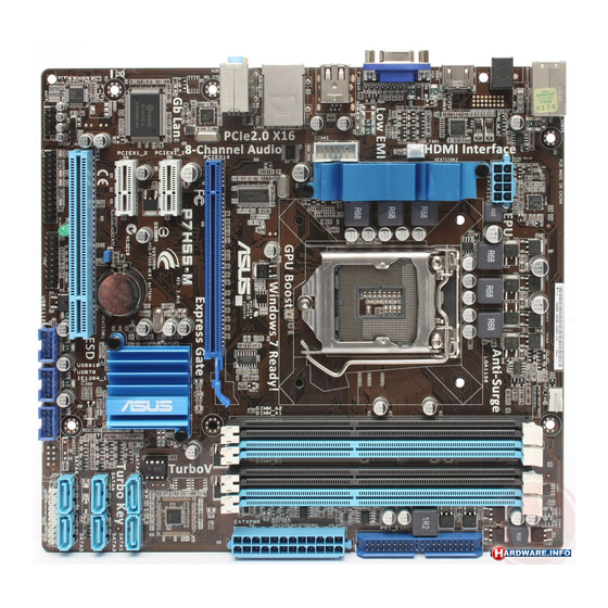
Page 19: Motherboard Layout
1.5.3 Motherboard layout 22.4cm(8.8in) KB_USB56 CPU_FAN ATX12V SPDIF_O2 HDMI CHA_FAN1 COM1 F_USB34 LAN1_USB12 AUDIO PCIEX16 8111E PCIEX1_1 SATA2 SATA1 Intel ® 64Mb SATA4 SATA3 BIOS Super SATA6 SATA5 PCIEX1_2 Lithium Cell CMOS Power CLRTC PCI1 SPDIF_OUT USB1112 USB910 USB78 SB_PWR AAFP PANEL 1.5.4... -
Page 20: Central Processing Unit (Cpu)
Contact your retailer immediately if the PnP cap is missing, or if you see any damage to the PnP cap/socket contacts/motherboard components. ASUS will shoulder the cost of repair only if the damage is shipment/transit-related. • Keep the cap after installing the motherboard. ASUS will process Return Merchandise Authorization (RMA) requests only if the motherboard comes with the cap on the LGA1156 socket. - Page 21 Lift the load lever in the direction of the arrow until the load plate is completely lifted. Load plate Remove the PnP cap from the CPU socket by lifting the tab only. PnP cap Cap tab Position the CPU over the socket, ensuring that the gold triangle is on the bottom-left corner of the socket, and CPU notches...
- Page 22 Close the load plate (A), and then push down the load lever (B), ensuring that the front edge of the load plate slides under the retention knob (C). Insert the load lever under the retention tab. ASUS P7H55-M 1-10...
-
Page 23: Installing The Cpu Heatsink And Fan
1.6.2 Installing the CPU heatsink and fan The Intel LGA1156 processor requires a specially designed heatsink and fan assembly to ® ensure optimum thermal condition and performance. • When you buy a boxed Intel processor, the package includes the CPU fan and ®... -
Page 24: Uninstalling The Cpu Heatsink And Fan
Connect the CPU fan cable to the connector on the motherboard labeled CPU_FAN. CPU_FAN P7H55-M CPU fan connector Do not forget to connect the CPU fan connector! Hardware monitoring errors can occur if you fail to plug this connector. 1.6.3... -
Page 25: System Memory
DDR2 DIMM socket. DDR3 modules are developed for better performance with less power consumption. The figure illustrates the location of the DDR3 DIMM sockets: Channel Sockets Channel A DIMM_A1 and DIMM_A2 Channel B DIMM_B1 and DIMM_B2 P7H55-M 240-pin DDR3 DIMM sockets 1-13 Chapter 1: Product introduction... -
Page 26: Memory Configurations
• Hyper DIMM support is subject to the physical characteristics of individual CPUs. • According to Intel spec definition, DDR3 1600+ is supported for one DIMM per channel only. ASUS exclusively provides two DDR3 1600+ DIMM support for each memory channel. - Page 27 P7H55-M Motherboard Qualified Vendors Lists (QVL) DDR3-2200(O.C.) MHz capability for Lynnfield CPU (2.8 GHz & 2.93 GHz) DIMM socket support Chip (Optional) Vendor Part No. Size SS/DS Chip NO. Timing Voltage Brand G.SKILL F3-17600CL8D-4GBPS(XMP) 4096MB(Kit of 2) 8-8-8-24 1.65V •...
- Page 28 4096MB(Kit of 2) 1.65V • • KINGSTON KHX1600C9D3K3/6GX(XMP) 6144MB(Kit of 3) 1.65V • • • OCZ3OB1600LV4GK 4096MB(Kit of 2) 1.65V • • • OCZ3X16004GK(XMP) 4096MB(Kit of 2) 7-7-7-24 1.9V • Super WA160UX6G9 6144MB(Kit of 3) • • • Talent ASUS P7H55-M 1-16...
- Page 29 • The QVL for the Clarkdale CPU is not included in this manual. You can get it from the ASUS website at www.asus.com • Visit the ASUS website at www.asus.com for the latest QVL. 1-17 Chapter 1: Product introduction...
-
Page 30: Installing A Dimm
Press the retaining clip outward to unlock the DIMM. Support the DIMM lightly with your fingers when pressing the retaining clip. The DIMM might get damaged when it flips out with extra force. Remove the DIMM from the socket. ASUS P7H55-M 1-18... -
Page 31: Expansion Slots
Expansion slots In the future, you may need to install expansion cards. The following sub-sections describe the slots and the expansion cards that they support. Unplug the power cord before adding or removing expansion cards. Failure to do so may cause you physical injury and damage motherboard components. -
Page 32: Jumpers
Normal Clear RTC (Default) P7H55-M Clear RTC RAM To erase the RTC RAM: 1. Turn OFF the computer and unplug the power cord. 2. Move the jumper cap from pins 1-2 (default) to pins 2-3. Keep the cap on pins 2-3 for about 5-10 seconds, then move the cap back to pins 1-2. -
Page 33: Connectors
1.10 Connectors 1.10.1 Rear panel connectors PS/2 Keyboard/Mouse Combo port (purple). This port is for a PS/2 keyboard or PS/2 mouse. LAN (RJ-45) port. This port allows Gigabit connection to a Local Area Network (LAN) through a network hub. Refer to the table below for the LAN port LED indications. LAN port LED indications Speed Activity Link... -
Page 34: Internal Connectors
Legacy AC’97 pin definition compliant definition P7H55-M Front panel audio connector • We recommend that you connect a high-definition front panel audio module to this connector to avail of the motherboard’s high-definition audio capability. • If you want to connect a high-definition front panel audio module to this connector, set the Front Panel Type item in the BIOS setup to [HD Audio]. -
Page 35: Ide Connectors
LPT connector (26-1 pin LPT) The LPT (Line Printing Terminal) connector supports devices such as a printer. LPT is standardized as IEEE 1284, which is the parallel port interface on IBM PC-compatible computers. PIN 1 P7H55-M Parallel port connector 1-23 Chapter 1: Product introduction... - Page 36 • If you are uncertain about the minimum power supply requirement for your system, refer to the Recommended Power Supply Wattage Calculator at http://support.asus. com/PowerSupplyCalculator/PSCalculator.aspx?SLanguage=en-us for details. Serial port connector (10-1 pin COM1) This connector is for a serial (COM) port.
- Page 37 These are not jumpers! Do not place jumper caps on the fan connectors! • Only the 4-pin CPU fan supports the ASUS Q-FAN feature. • The CPU_FAN connector supports a CPU fan of maximum 2A (24 W) fan power.
- Page 38 SATA1 SATA4 SATA3 SATA6 SATA5 P7H55-M SATA connectors Install the Windows XP Service Pack 2 or later version before using Serial ATA. ® USB connectors (10-1 pin USB78, USB910, USB1112) These connectors are for USB 2.0 ports. Connect the USB module cable to any of these connectors, then install the module to a slot opening at the back of the system chassis.
-
Page 39: System Panel Connector (20-8 Pin Panel)
IDE_LED PWRSW RESET * Requires an ATX power supply P7H55-M System panel connector • System power LED (2-pin PLED) This 2-pin connector is for the system power LED. Connect the chassis power LED cable to this connector. The system power LED lights up when you turn on the system power, and blinks when the system is in sleep mode. -
Page 40: Software Support
Place the Support DVD to the optical drive. If Autorun is enabled in your computer, the DVD automatically displays the Specials screen which contains the unique feature of ASUS motherboard. Click Drivers, Utilities, Make Disk, Manual, and Contact tabs to display their respective menus. -
Page 41: Chapter 2: Bios Information
BIOS in the future. Copy the original motherboard BIOS using the ASUS Update utility. 2.1.1 ASUS Update utility The ASUS Update is a utility that allows you to manage, save, and update the motherboard BIOS in Windows environment. ®... -
Page 42: Asus Ez Flash
Follow the onscreen instructions to complete the updating process. 2.1.2 ASUS EZ Flash 2 The ASUS EZ Flash 2 feature allows you to update the BIOS without using an OS-based utility. Before you start using this utility, download the latest BIOS file from the ASUS website at www.asus.com. -
Page 43: Asus Crashfree Bios
2.1.3 ASUS CrashFree BIOS The ASUS CrashFree BIOS is an auto recovery tool that allows you to restore the BIOS file when it fails or gets corrupted during the updating process. You can restore a corrupted BIOS file using the motherboard support DVD or a removable device that contains the updated BIOS file. - Page 44 Insert the USB flash drive with the latest BIOS file and BIOS Updater to the USB port. Boot your computer. When the ASUS Logo appears, press <F8> to show the BIOS Boot Device Select Menu. Insert the support DVD into the optical drive and select the optical drive as the boot device.
-
Page 45: Updating The Bios File
ASUSTek BIOS Updater for DOS V1.00b [09/06/22] Current ROM Update ROM BOARD: P7H55-M BOARD: Unknown VER: 0208 VER: Unknown DATE: 1/15/2010 DATE: Unknown PATH: BIOS backup is done! Press any key to continue. Note Saving BIOS: Updating the BIOS file To update the BIOS file using BIOS Updater At the FreeDOS prompt, type bupdater /pc /g and press <Enter>. -
Page 46: Bios Setup Program
• The BIOS setup screens shown in this section are for reference purposes only, and may not exactly match what you see on your screen. • Visit the ASUS website at www.asus.com to download the latest BIOS file for this motherboard. -
Page 47: Bios Menu Screen
2.2.1 BIOS menu screen Menu items Menu bar Configuration fields General help BIOS SETUP UTILITY Main Ai Tweaker Advanced Power Boot Tools Exit Use [ENTER], [TAB] or System Time [12:56:38] [SHIFT-TAB] to select System Date [Tue 01/01/2002] a field. Language [English] Use [+] or [-] to SATA1... -
Page 48: Submenu Items
:[Not Detected] SATA5 :[Not Detected] SATA6 :[Not Detected] Select Screen Storage Configuration Select Item System Information Change Field Select Field General Help Save and Exit Exit v02.61 (C)Copyright 1985-2009, American Megatrends, Inc. v02.61 (C)Copyright 1985-2009, American Megatrends, Inc. ASUS P7H55-M... -
Page 49: System Time
2.3.1 System Time [xx:xx:xx] Allows you to set the system time. 2.3.2 System Date [Day xx/xx/xxxx] Allows you to set the system date. 2.3.3 Language [English] Allows you to choose the BIOS language version from the options. Configuration options: [Chinese (Trad.)] [Chinese (Simp.)] [Japanese] [French] [Deutsch] [English] 2.3.4 SATA1~6 While entering Setup, the BIOS automatically detects the presence of SATA devices. -
Page 50: Storage Configuration
This menu gives you an overview of the general system specifications. The BIOS automatically detects the items in this menu. BIOS Information Displays the auto-detected BIOS information Processor Displays the auto-detected CPU specification System Memory Displays the auto-detected system memory 2-10 ASUS P7H55-M... -
Page 51: Ai Tweaker Menu
Ai Tweaker menu The Ai Tweaker menu items allow you to configure overclocking-related items. Be cautious when changing the settings of the Ai Tweaker menu items. Incorrect field values can cause the system to malfunction. The configuration options for this chapter vary depending on the CPU and DIMM model you installed on the motherboard. -
Page 52: Cpu Ratio Setting
D.O.C.P. D.O.C.P. • When using DIMMs with afrequency higher than the Intel CPU spec, use this ASUS ® exclusive DRAM O.C. Profile function to overclock the DRAM. • Adjust BCLK frequency to obtain a better performance after applying the D.O.C.P. -
Page 53: Bclk Frequency
The following two items appear only when you set the Ai Overclock Tuner item to [Manual], [D.O.C.P.] or [X.M.P.]. 2.4.5 BCLK Frequency [XXX] Allows you to adjust the Internal Base Clock (BCLK). Use the <+> and <-> keys to adjust the value. - Page 54 Configuration options: [Auto] [2 DRAM Clock] ~ [14 DRAM Clock] DRAM READ to READ Delay(DD) [Auto] Configuration options: [Auto] [2 DRAM Clock] ~ [9 DRAM Clock] DRAM READ to READ Delay(DR) [Auto] Configuration options: [Auto] [2 DRAM Clock] ~ [9 DRAM Clock] 2-14 ASUS P7H55-M...
-
Page 55: Cpu Differential Amplitude
DRAM READ to READ Delay(SR) [Auto] Configuration options: [Auto] [4 DRAM Clock] [6 DRAM Clock] DRAM WRITE to WRITE Delay(DD) [Auto] Configuration options: [Auto] [2 DRAM Clock] ~ [9 DRAM Clock] DRAM WRITE to WRITE Delay(DR) [Auto] Configuration options: [Auto] [2 DRAM Clock] ~ [9 DRAM Clock] DRAM WRITE to WRITE Delay(SR) [Auto] Configuration options: [Auto] [4 DRAM Clock] [6 DRAM Clock] 2.4.10... -
Page 56: Dram Voltage
PCIE Spread Spectrum [Auto] [Auto] Automatic configuration. [Disabled] Enhances the PCIE overclocking ability. [Enabled] Sets to [Enabled] for EMI control. 2.4.11 PCI/PCIe CLK Status [Enabled] Allows you to enable or disable clock for PCI/PCI Express ports. Configuration options: [Disabled] [Enabled] 2-16 ASUS P7H55-M... -
Page 57: Advanced Menu
Advanced menu The Advanced menu items allow you to change the settings for the CPU and other system devices. Be cautious when changing the settings of the Advanced menu items. Incorrect field values can cause the system to malfunction. BIOS SETUP UTILITY Main Ai Tweaker Advanced... - Page 58 The CPU runs at its default speed. Intel(R) C-STATE Tech [Disabled] [Enabled] Allows the CPU to save more power under idle mode. Enable this item only when you install a C-State Technology-supported CPU. [Disabled] Disables this function. 2-18 ASUS P7H55-M...
-
Page 59: Uncore Configuration
2.5.2 Uncore Configuration The North Bridge Configuration menu allows you to change the advanced chipset settings. Memory Remap Feature [Enabled] [Disabled] Do not allow remapping of memory. [Enabled] Allows for the segment of system memory that was previously overwritten by PCI devices to be remapped above the total physical memory. -
Page 60: Usb Configuration
Plug and Play operating system, the operating system configures the Plug and Play devices not required for boot. Configuration options: [No] [Yes] 2.5.6 Intel VT-d [Disabled] Enables or disables the Intel Virtualization Technology for Directed I/O. Configuration options: [Enabled] [Disabled] 2-20 ASUS P7H55-M... -
Page 61: Power Menu
Power menu The Power menu items allow you to change the settings for the Advanced Power Management (APM). Select an item then press <Enter> to display the configuration options. BIOS SETUP UTILITY Main Ai Tweaker Advanced Power Boot Tools Exit Select the ACPI state Suspend Mode [Auto]... -
Page 62: Hardware Monitor
CPU Fan Speed Low Limit [200] This item appears only when you enable the CPU Q-Fan Control feature and allows you to set the low limit of the CPU fan speed. Configuration options: [500] [400] [300] [200] [100] [Ignored] 2-22 ASUS P7H55-M... -
Page 63: Anti Surge Support
CPU Q-Fan Control [Enabled] [Disabled] Disables the CPU Q-Fan control feature. [Enabled] Enables the CPU Q-Fan control feature. CPU Fan Profile [Standard] This item appears only when you enable the CPU Q-Fan Control feature and allows you to set the appropriate performance level of the CPU fan. [Standard] Sets to [Standard] to make the CPU fan automatically adjust depending on the CPU temperature. -
Page 64: Boot Menu
Configuration options: [Removable Dev.] [Hard Drive] [ATAPI CD-ROM] [Disabled] • To select the boot device during system startup, press <F8> when ASUS Logo appears. • To access Windows OS in Safe Mode, do any of the following: ®... -
Page 65: Security
Bootup Num-Lock [On] Selects the power-on state for the NumLock. Configuration options: [Off] [On] Wait for ‘F1’ If Error [Enabled] When this item is set to [Enabled], the system waits for the F1 key to be pressed when error occurs. Configuration options: [Disabled] [Enabled] Hit ‘DEL’... -
Page 66: Tools Menu
Ai Tweaker Advanced Power Boot Tools Exit Tools Settings ASUS O.C. Profile AI NET 2 ASUS EZ Flash 2 Express Gate [Auto] Enter OS Timer [10 Seconds] Reset User Data [No] 2.8.1 ASUS O.C. Profile This item allows you to store or load multiple BIOS settings. -
Page 67: Ai Net 2
2.8.3 ASUS EZ Flash 2 Allows you to run ASUS EZ Flash 2. When you press <OK>, a confirmation message appears. Use the left/right arrow key to select between [Yes] or [No], then press <OK> to confirm your choice. See section 2.1.2 ASUS EZ Flash 2 for details. -
Page 68: Exit Menu
When you select this option or if you press <F5>, a confirmation window appears. Select Ok to load default values. Select Exit & Save Changes or make other changes before saving the values to the non-volatile RAM. 2-28 ASUS P7H55-M...
Need help?
Do you have a question about the P7H55-M and is the answer not in the manual?
Questions and answers