Table of Contents
Advertisement
Advertisement
Chapters
Table of Contents

Related Manuals for Asus B75M-PLUS


Summary of Contents for Asus B75M-PLUS
- Page 1 B75M-PLUS...
- Page 2 Product warranty or service will not be extended if: (1) the product is repaired, modified or altered, unless such repair, modification of alteration is authorized in writing by ASUS; or (2) the serial number of the product is defaced or missing.
-
Page 3: Table Of Contents
Contents Safety information ...................... iv About this guide ......................iv Package contents ....................... vi B75M-PLUS specifications summary ............... vi Chapter 1: Product introduction Before you proceed ..................1-1 Motherboard overview ................. 1-1 Central Processing Unit (CPU) ..............1-3 System memory .................... 1-7 Expansion slots .................. -
Page 4: Safety Information
Safety information Electrical safety • To prevent electrical shock hazard, disconnect the power cable from the electrical outlet before relocating the system. • When adding or removing devices to or from the system, ensure that the power cables for the devices are unplugged before the signal cables are connected. If possible, disconnect all power cables from the existing system before you add a device. -
Page 5: Conventions Used In This Guide
Refer to the following sources for additional information and for product and software updates. ASUS websites The ASUS website provides updated information on ASUS hardware and software products. Refer to the ASUS contact information. Optional documentation Your product package may include optional documentation, such as warranty flyers, that may have been added by your dealer. -
Page 6: Package Contents
* The maximum 32GB memory capacity can be supported with 8GB (or higher). ASUS will update the QVL once the DIMMs are available in the market. ** Due to the CPU behavior, DDR3 2133/1866MHz memory module will run at DDR3 2000/1800MHz frequency. - Page 7 8 x USB 2.0 ports (4 ports at midboard, 4 ports at back panel) ASUS DIGI+VRM ASUS unique features - ASUS DIGI+VRM: Digital Power Design for the CPU and iGPU - ASUS 3+1 Phase Power Design ASUS Eclusive Features - ASUS EPU - ASUS USB 3.0 Boost...
- Page 8 1 x Speaker connector BIOS features 64 Mb Flash ROM, AMI BIOS, PnP, DMI2.0, WfM2.0, SM BIOS 2.7, ACPI 2.0a, Multi-language BIOS, ASUS EZ Flash 2, ASUS CrashFree BIOS 3 Manageability WfM 2.0, DMI 2.0, WOL by PME, WOR by PME, PXE...
-
Page 9: Chapter 1: Product Introduction
The edge with external ports goes to the rear part of the chassis as indicated in the image below. 1.2.2 Screw holes Place six screws into the holes indicated by circles to secure the motherboard to the chassis. Do not overtighten the screws! Doing so can damage the motherboard. ASUS B75M-PLUS... -
Page 10: Motherboard Layout
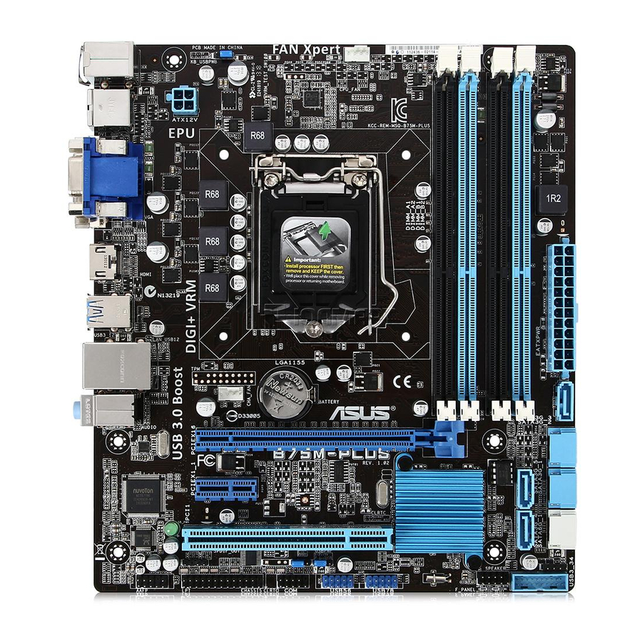
Place this side towards the rear of the chassis B75M-PLUS 1.2.3 Motherboard layout 19.8cm(7.8in) KBMS CPU_FAN DIGI +VRM USB34 ATX12V HDMI USB3_12 LAN1_USB12 BATTERY AUDIO CHA_FAN PCIEX16 8111G B75M-PLUS BIOS PCIEX1_1 Super Intel ® SB_PWR PCI1 SPDIF_OUT SPEAKER USB56 USB78... -
Page 11: Central Processing Unit (Cpu)
This motherboard comes with a surface mount LGA1155 socket designed for the Intel 3rd/2nd generation Core™ i7 / Core™ i5 / Core™ i3 / Pentium / Celeron processors. ® ® B75M-PLUS B75M-PLUS CPU socket LGA1155 Unplug all power cables before installing the CPU. ASUS B75M-PLUS... -
Page 12: Installing The Cpu
Contact your retailer immediately if the PnP cap is missing, or if you see any damage to the PnP cap/socket contacts/motherboard components. ASUS will shoulder the cost of repair only if the damage is shipment/ transit-related. -
Page 13: Cpu Heatsink And Fan Assembly Installation
1.3.2 CPU heatsink and fan assembly installation Apply the Thermal Interface Material to the CPU heatsink and CPU before you install the heatsink and fan if necessary. ASUS B75M-PLUS... - Page 14 To install the CPU heatsink and fan assembly To uninstall the CPU heatsink and fan assembly Chapter 1: Product introduction...
-
Page 15: System Memory
DDR2 DIMM socket. DDR3 modules are developed for better performance with less power consumption. The figure illustrates the location of the DDR3 DIMM sockets: B75M-PLUS B75M-PLUS 240-pin DDR3 DIMM sockets Channel Sockets Channel A... -
Page 16: Installing A Dimm
• The maximum 32GB memory capacity can be supported with 8GB or above DIMMs. ASUS will update the memory QVL once the DIMMs are available in the market. • The default memory operation frequency is dependent on its Serial Presence Detect (SPD), which is the standard way of accessing information from a memory module. - Page 17 To remove a DIMM ASUS B75M-PLUS...
-
Page 18: Expansion Slots
Expansion slots In the future, you may need to install expansion cards. The following sub-sections describe the slots and the expansion cards that they support. Unplug the power cord before adding or removing expansion cards. Failure to do so may cause you physical injury and damage motherboard components. -
Page 19: Jumpers
B75M-PLUS Normal Clear RTC (Default) B75M-PLUS Clear RTC RAM To erase the RTC RAM: Turn OFF the computer and unplug the power cord. Move the jumper cap from pins 1-2 (default) to pins 2-3. Keep the cap on pins 2-3 for about 5-10 seconds, then move the cap back to pins 1-2. -
Page 20: Keyboard And Usb Device Wake-Up (Kb_Usbpwb)
+5VSB (Default) B75M-PLUS B75M-PLUS Keyboard and USB device wake up USB device wake-up (USBPWF) Set this jumper to +5V to wake up the computer from S1 sleep mode (CPU stopped, DRAM refreshed, system running in low power mode) using the connected USB devices. -
Page 21: Connectors
Line Out port (lime). This port connects to a headphone or a speaker. In the 4, 6 and 8-channel configurations, the function of this port becomes Front Speaker Out. Microphone port (pink). This port connects to a microphone. ASUS B75M-PLUS 1-13... - Page 22 Refer to the audio configuration table for the function of the audio ports in 2, 4, 6, or 8- channel configuration. Audio 2, 4, 6, or 8-channel configuration Headset Port 4-channel 6-channel 8-channel 2-channel Light Blue (Rear Line In Rear Speaker Out Rear Speaker Out Rear Speaker Out panel)
-
Page 23: Atx Power Connectors (24-Pin Eatxpwr, 4-Pin Atx12V)
B75M-PLUS HD-audio-compliant Legacy AC’97 pin definition compliant definition B75M-PLUS Front panel audio connector • We recommend that you connect a high-definition front panel audio module to this connector to avail of the motherboard’s high-definition audio capability. • If you want to connect a high-definition front panel audio module to this connector, set the Front Panel Type item in the BIOS setup to [HD]. -
Page 24: Cpu And Chassis Fan Connectors (4-Pin Cpu_Fan, 4-Pin Cha_Fan)
• If you are uncertain about the minimum power supply requirement for your system, refer to the Recommended Power Supply Wattage Calculator at http://support.asus. com/PowerSupplyCalculator/PSCalculator.aspx?SLanguage=en-us for details. CPU and chassis fan connectors (4-pin CPU_FAN, 4-pin CHA_FAN) Connect the fan cables to the fan connectors on the motherboard, ensuring that the black wire of each cable matches the ground pin of the connector. -
Page 25: Speaker Connector (4-Pin Speaker)
PIN 1 B75M-PLUS HDD_LED RESET B75M-PLUS System panel connector • System power LED (2-pin PWR_LED) This 2-pin connector is for the system power LED. Connect the chassis power LED cable to this connector. The system power LED lights up when you turn on the system power, and blinks when the system is in sleep mode. -
Page 26: Intel ® B75 Serial Ata 3.0Gb/S Connectors (7-Pin Sata3G_1~5 [Blue])
RSATA_TXP5 SATA3G_4 B75M-PLUS RSATA_RXP4 RSATA_RXN4 RSATA_TXN4 RSATA_TXP4 B75M-PLUS Intel SATA 3.0Gb/s connectors ® • You must install Windows. XP Service Pack 3 or later version before using Serial ATA ® hard disk drives. • When using hot-plug and NCQ, set the SATA Mode Selection item in the BIOS to [AHCI]. -
Page 27: Usb 3.0 Connector (20-1 Pin Usb3_34)
This connector is for additional USB 3.0 ports. Connect the USB 3.0 bracket cable to this connector, then install the USB 3.0 bracket to the rear side of the chassis. If your chassis supports front panel ports, you can use the ASUS USB 3.0 header to install additional front panel USB 3.0 ports. -
Page 28: Serial Port Connectors (10-1 Pin Com)
PIN 1 B75M-PLUS B75M-PLUS Serial port (COM) connector The COM module is purchased separately. Digital audio connector (4-1 pin SPDIF_OUT) This connector is for an additional Sony/Philips Digital Interface (S/PDIF) port. Connect the S/PDIF Out module cable to this connector, then install the module to a slot opening at the back of the system chassis. -
Page 29: Onboard Leds
The LPT (Line Printing Terminal) connector supports devices such as a printer. LPT standardizes as IEEE 1284, which is the parallel port interface on IBM PC-compatible computers. B75M-PLUS B75M-PLUS Parallel Port Connector Onboard LEDs Standby Power LED The motherboard comes with a standby power LED that lights up to indicate that the system is ON, in sleep mode, or in soft-off mode. -
Page 30: Software Support
Place the Support DVD into the optical drive. If Autorun is enabled in your computer, the DVD automatically displays the Specials screen which contains the unique features of ASUS motherboard. Click Drivers, Utilities, Make Disk, Manual, and Contact tabs to display their respective menus. -
Page 31: Chapter 2: Bios Information
Managing and updating your BIOS Save a copy of the original motherboard BIOS file to a USB flash disk in case you need to restore the BIOS in the future. Copy the original motherboard BIOS using the ASUS Update utility. -
Page 32: Asus Ez Flash
2.1.3 ASUS CrashFree BIOS 3 utility The ASUS CrashFree BIOS 3 is an auto recovery tool that allows you to restore the BIOS file when it fails or gets corrupted during the updating process. You can restore a corrupted BIOS file using the motherboard support DVD or a USB flash drive that contains the updated BIOS file. -
Page 33: Recovering The Bios
2.1.4 ASUS BIOS Updater The ASUS BIOS Updater allows you to update BIOS in DOS environment. This utility also allows you to copy the current BIOS file that you can use as a backup when the BIOS fails or gets corrupted during the updating process. - Page 34 Insert the USB flash drive with the latest BIOS file and BIOS Updater to the USB port. Boot your computer. When the ASUS Logo appears, press <F8> to show the BIOS Boot Device Select Menu. Insert the support DVD into the optical drive and select the optical drive as the boot device.
- Page 35 Ensure to load the BIOS default settings to ensure system compatibility and stability. Select the Load Optimized Defaults item under the Exit menu. Refer to section 2.9 Exit menu for details. • Ensure to connect all SATA hard disk drives after updating the BIOS file if you have disconnected them. ASUS B75M-PLUS...
-
Page 36: Bios Setup Program
The BIOS setup screens shown in this section are for reference purposes only, and may not exactly match what you see on your screen. Visit the ASUS website at www.asus.com to download the latest BIOS file for this • motherboard. -
Page 37: Advanced Mode
The Advanced Mode provides advanced options for experienced end-users to configure the BIOS settings. The figure below shows an example of the Advanced Mode. Refer to the following sections for the detailed configurations. To access the EZ Mode, click Exit, then select ASUS EZ Mode. ASUS B75M-PLUS... -
Page 38: Menu Bar
Back button Menu items Menu bar Configuration fields General help Pop-up window Submenu item Navigation keys Menu bar The menu bar on top of the screen has the following main items: Main For changing the basic system configuration Ai Tweaker For changing the overclocking settings Advanced For changing the advanced system settings... -
Page 39: Main Menu
The Main menu screen appears when you enter the Advanced Mode of the BIOS Setup program. The Main menu provides you an overview of the basic system information, and allows you to set the system date, time, language, and security settings. ASUS B75M-PLUS... -
Page 40: Administrator Password
2.3.1 System Language [English] Allows you to choose the BIOS language version from the options. Configuration options: [English] [Español] [Русский] [한국어] 2.3.2 System Date [Day xx/xx/xxxx] Allows you to set the system date. 2.3.3 System Time [xx:xx:xx] Allows you to set the system time. 2.3.4 Security The Security menu items allow you to change the system security settings. -
Page 41: Ai Tweaker Menu
Be cautious when changing the settings of the Ai Tweaker menu items. Incorrect field values can cause the system to malfunction. The configuration options for this section vary depending on the CPU and DIMM model you installed on the motherboard. ASUS B75M-PLUS 2-11... - Page 42 Scroll down to display the other items. Target DRAM Speed : xxxxMHz Displays the current DRAM speed. 2.4.1 Ai Overclock Tuner [Auto] Allows you to select the CPU overclocking options to achieve the desired CPU internal frequency. Select any of these preset overclocking configuration options: [Auto] Loads the optimal settings for the system.
-
Page 43: Dram Timing Control
Changing the values in this menu may cause the system to become unstable! If this happens, revert to the default settings. 2.4.8 CPU Power Management The subitems in this menu allow you to set the CPU ratio and features. ASUS B75M-PLUS 2-13... - Page 44 2.4.9 DIGI+ VRM CPU Load-Line Calibration [Auto] Load-line is defined by Intel VRM specification and affects CPU voltage. The CPU working voltage will decrease proportionally to CPU loading. Higher value gets a higher voltage and better overclocking performance, but increases the CPU and VRM thermal conditions. This item allows you to adjust the voltage range from the following percentages to boost the system performance: 0% (Regular), 25% (Medium), 50% (High), 75% (Ultra High), and 100% (Extreme).
- Page 45 CPU permanently, and setting a low voltage may make the system unstable. CPU Manual Voltage [Auto] This item appears when you set the CPU Voltage to [Manual Mode]. You can manually key in a value for the CPU voltage. ASUS B75M-PLUS 2-15...
- Page 46 2.4.8 iGPU Voltage [Offset Mode] iGPU Offset Mode Sign [+] This item appears when you set the iGPU Voltage to [Offset Mode]. To offset the voltage by a positive value. [–] To offset the voltage by a negative value. iGPU Offset Voltage [Auto] Allows you to set the iGPU Offset voltage.
-
Page 47: Advanced Menu
Two threads per activated core are enabled. [Disabled] Only one thread per activated core is enabled. Active Processor Cores [All] Allows you to choose the number of CPU cores to activate in each processor package. Configuration options: [All] [1] [2] [3] ASUS B75M-PLUS 2-17... - Page 48 Limit CPUID Maximum [Disabled] [Enabled] Allows legacy operating systems to boot even without support for CPUs with extended CPUID functions. [Disabled] Disables this function. Execute Disable Bit [Enabled] [Enabled] Enables the No-Execution Page Protection Technology. [Disabled] Forces the XD feature flag to always return to zero (0). Intel Virtualization Technology [Disabled] [Enabled] Allows a hardware platform to run multiple operating systems separately...
-
Page 49: Pch Configuration
The system automatically goes into sleep mode when the partition size is not enough for the Intel Rapid Start Technology to work. Configuration options: [Enabled] ® [Disabled] Intel Smart Connect Technology ISCT Support [Disabled] Allow you to enable or disable the Intel Smart Connect Technology. Configuration ® options: [Enabled] [Disabled] ASUS B75M-PLUS 2-19... -
Page 50: Sata Configuration
2.5.3 SATA Configuration While entering Setup, the BIOS automatically detects the presence of SATA devices. The SATA Port items show Not Present if no SATA device is installed to the corresponding SATA port. SATA Mode Selection [AHCI] Allows you to set the SATA configuration. [Disabled] Disables the SATA function. -
Page 51: Usb Configuration
Disables the function. Intel xHCI Mode [Smart Auto] [Auto] Keeps the last operation of xHCI controller in OS during bootup. [Smart Auto] Enables the operation of xHCI controller. [Enabled] Enables the xHCI controller. [Disabled] Disables the xHCI controller. ASUS B75M-PLUS 2-21... -
Page 52: Onboard Devices Configuration
EHCI Hand-off [Disabled] [Enabled] Enables the support for operating systems without an EHCI hand-off feature. [Disabled] Disables the function. USB Single Port Control Allows you to enable or disable the individual USB port. Refer to section 1.2.2 Motherboard layout for the location of the USB ports. 2.5.6 Onboard Devices Configuration HD Audio Controller [Enabled]... -
Page 53: Serial Port Configuration
Sets the Ctrl+Esc key on the PS/2 keyboard to turn on the system. [Power Key] Sets Power key on the PS/2 keyboard to turn on the system. This feature requires an ATX power supply that provides at least 1A on the +5VSB lead. ASUS B75M-PLUS 2-23... -
Page 54: Monitor Menu
Power On By PCIE/PCI [Disabled] [Disabled] Disables the PCIE/PCI devices to generate a wake-on-LAN feature of the Realtek LAN device or other installed PCIE/PCI LAN devices. [Enabled] Enables the PCIE/PCI devices to generate a wake-on-LAN feature of the Realtek LAN device or other installed PCIE/PCI LAN devices. Power On By Ring [Disabled] [Disabled] Disables Ring to generate a wake event. - Page 55 Use the <+> and <-> keys to adjust the minimum CPU fan duty cycle. The values range from 40% to 100%. When the CPU temperature is under 20ºC, the CPU fan will operate at the minimum duty cycle. ASUS B75M-PLUS 2-25...
- Page 56 2.6.4 Chassis Q-Fan Control [Enabled] [Disabled] Disables the Chassis Q-Fan control feature. [Enabled] Enables the Chassis Q-Fan control feature. Chassis Fan Speed Low Limit [600 RPM] This item appears only when you enable the Chassis Q-Fan Control feature and allows you to disable or set the chassis fan warning speed.
-
Page 57: Boot Menu
POST time. [Full Initialization] All USB devices will be available during POST. This process will extend the POST time. [Partial Initialization] For a faster POST time, only the USB ports with keyboard and mouse connections will be detected. ASUS B75M-PLUS 2-27... - Page 58 PS/2 Keyboard and Mouse Support [Auto] Select any of these settings when PS/2 keyboard and mouse are installed. These settings only apply when Fast Boot is enabled. [Auto] For a faster POST time, PS/2 devices will only be available when the system boots up or rebooted when the PS/2 devices have not been reconnected or changed.
- Page 59 Boot from Storage Devices [Legacy OpROM first] Allows you to select the type of storage devices that you want to launch. Configuration options: [Both, Legacy OpROM first] [Both, UEFI first] [Legacy OpROM first] [UEFI driver first] [Ignore] ASUS B75M-PLUS 2-29...
-
Page 60: Security Boot
Boot from PCIe/PCI Expansion Devices [Legacy OpROM first] Allows you to select the type of PCIe/PCI expansion devices that you want to launch. Configuration options: [Legacy OpROM first] [UEFI driver first] 2.7.10 Security Boot Allows you to configure the Windows Secure Boot settings and manage its keys to protect ®... - Page 61 Append DB from file Allows you to load the additional DB from a storage device so that more images can be loaded securely. The DB file must be formatted as a UEFI variable structure with time-based authenticated variable. ASUS B75M-PLUS 2-31...
-
Page 62: Boot Option Priorities
• To select the boot device during system startup, press <F8> when ASUS Logo appears. • To access Windows OS in Safe Mode, do any of the following: •... -
Page 63: Tools Menu
<Enter> to display the submenu. 2.8.1 ASUS EZ Flash 2 Utility Allows you to run ASUS EZ Flash 2. Press [Enter] to launch the ASUS EZ Flash 2 screen. For more details, see section 2.1.2 ASUS EZ Flash 2. 2.8.2... -
Page 64: Exit Menu
This option allows you to exit the Setup program without saving your changes. When you select this option or if you press <Esc>, a confirmation window appears. Select Yes to discard changes and exit. ASUS EZ Mode This option allows you to enter the EZ Mode screen. Launch EFI Shell from filesystem device This option allows you to attempt to launch the EFI Shell application (shellx64.efi) from one of... -
Page 65: Appendices
The use of shielded cables for connection of the monitor to the graphics card is required to assure compliance with FCC regulations. Changes or modifications to this unit not expressly approved by the party responsible for compliance could void the user’s authority to operate this equipment. ASUS B75M-PLUS... -
Page 66: Canadian Department Of Communications Statement
IC: Canadian Compliance Statement Complies with the Canadian ICES-003 Class B specifications. This device complies with RSS 210 of Industry Canada. This Class B device meets all the requirements of the Canadian interference-causing equipment regulations. This device complies with Industry Canada license exempt RSS standard(s). Operation is subject to the following two conditions: (1) this device may not cause interference, and (2) this device must accept any interference, including interference that may cause undesired operation of the device. - Page 67 ASUS Recycling/Takeback Services ASUS recycling and takeback programs come from our commitment to the highest standards for protecting our environment. We believe in providing solutions for you to be able to responsibly recycle our products, batteries, other components as well as the packaging materials.
-
Page 68: Asus Contact Information
+1-812-282-3777 +1-510-608-4555 Web site usa.asus.com Technical Support Telephone +1-812-282-2787 Support fax +1-812-284-0883 Online support support.asus.com ASUS COMPUTER GmbH (Germany and Austria) Address Harkort Str. 21-23, D-40880 Ratingen, Germany +49-2102-959911 Web site www.asus.de Online contact www.asus.de/sales Technical Support Telephone +49-1805-010923* Support Fax... - Page 69 ASUS B75M-PLUS...
Need help?
Do you have a question about the B75M-PLUS and is the answer not in the manual?
Questions and answers