Table of Contents
Advertisement
Advertisement
Table of Contents

Related Manuals for Asus B75M-PLUS


Summary of Contents for Asus B75M-PLUS
- Page 1 B75M-PLUS...
- Page 2 INCIDENTAL, OR CONSEQUENTIAL DAMAGES (INCLUDING DAMAGES FOR LOSS OF PROFITS, LOSS OF BUSINESS, LOSS OF USE OR DATA, INTERRUPTION OF BUSINESS AND THE LIKE), EVEN IF ASUS HAS BEEN ADVISED OF THE POSSIBILITY OF SUCH DAMAGES ARISING FROM ANY DEFECT OR ERROR IN THIS MANUAL OR PRODUCT.
-
Page 3: Table Of Contents
Contents Safety information ...................... iv About this guide ......................iv Package contents ....................... vi ............... vi Chapter 1: Product introduction Before you proceed ..................1-1 Motherboard overview ................. 1-1 Central Processing Unit (CPU) ..............1-3 System memory .................... 1-7 Expansion slots ..................1-10 Jumpers....................... -
Page 4: Safety Information
Safety information Electrical safety • before relocating the system. • When adding or removing devices to or from the system, ensure that the power cables for the devices are unplugged before the signal cables are connected. If possible, disconnect all power cables from the existing system before you add a device. •... - Page 5 Refer to the following sources for additional information and for product and software updates. ASUS websites The ASUS website provides updated information on ASUS hardware and software products. Refer to the ASUS contact information. Optional documentation that may have been added by your dealer. These documents are not part of the standard package.
-
Page 6: Package Contents
* The maximum 32GB memory capacity can be supported with 8GB (or higher). ASUS will update the QVL once the DIMMs are available in the market. ** Due to the CPU behavior, DDR3 2133/1866MHz memory module will run at DDR3 2000/1800MHz frequency. - Page 7 8 x USB 2.0 ports (4 ports at midboard, 4 ports at back panel) ASUS unique ASUS DIGI+VRM features - ASUS DIGI+VRM: Digital Power Design for the CPU and iGPU - ASUS 3+1 Phase Power Design ASUS Eclusive Features - ASUS EPU - ASUS USB 3.0 Boost...
- Page 8 1 x Speaker connector BIOS features 64 Mb Flash ROM, AMI BIOS, PnP, DMI2.0, WfM2.0, SM BIOS 2.7, ACPI 2.0a, Multi-language BIOS, ASUS EZ Flash 2, ASUS CrashFree BIOS 3 Manageability WfM 2.0, DMI 2.0, WOL by PME, WOR by PME, PXE...
-
Page 9: Chapter 1: Product Introduction
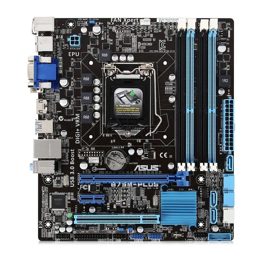
The edge with external ports goes to the rear part of the chassis as indicated in the image below. 1.2.2 Screw holes Place six screws into the holes indicated by circles to secure the motherboard to the chassis. Do not overtighten the screws! Doing so can damage the motherboard. ASUS B75M-PLUS... - Page 10 Place this side towards the rear of the chassis B75M-PLUS 1.2.3 Motherboard layout 19.8cm(7.8in) KBMS CPU_FAN DIGI +VRM USB34 ATX12V HDMI USB3_12 LAN1_USB12 BATTERY AUDIO CHA_FAN PCIEX16 8111G B75M-PLUS BIOS PCIEX1_1 Super ® Intel SB_PWR PCI1 SPDIF_OUT SPEAKER USB56 USB78...
-
Page 11: Central Processing Unit (Cpu)
This motherboard comes with a surface mount LGA1155 socket designed for the Intel ® ® 3rd/2nd generation Core™ i7 / Core™ i5 / Core™ i3 / Pentium / Celeron processors. B75M-PLUS B75M-PLUS CPU socket LGA1155 Unplug all power cables before installing the CPU. ASUS B75M-PLUS... - Page 12 Contact your retailer immediately if the PnP cap is missing, or if you see any damage to the PnP cap/socket contacts/motherboard components. ASUS will shoulder the cost of repair only if the damage is shipment/ transit-related.
- Page 13 1.3.2 CPU heatsink and fan assembly installation Apply the Thermal Interface Material to the CPU heatsink and CPU before you install the heatsink and fan if necessary. ASUS B75M-PLUS...
- Page 14 To install the CPU heatsink and fan assembly To uninstall the CPU heatsink and fan assembly Chapter 1: Product introduction...
-
Page 15: System Memory
(DIMM) sockets. A DDR3 module has the same physical dimensions as a DDR2 DIMM but is notched differently to prevent installation on a DDR2 DIMM socket. DDR3 modules are location of the DDR3 DIMM sockets: B75M-PLUS B75M-PLUS 240-pin DDR3 DIMM sockets Channel Sockets Channel A... - Page 16 • The maximum 32GB memory capacity can be supported with 8GB or above DIMMs. ASUS will update the memory QVL once the DIMMs are available in the market. • The default memory operation frequency is dependent on its Serial Presence Detect (SPD), which is the standard way of accessing information from a memory module.
- Page 17 To remove a DIMM ASUS B75M-PLUS...
-
Page 18: Expansion Slots
Expansion slots In the future, you may need to install expansion cards. The following sub-sections describe the slots and the expansion cards that they support. Unplug the power cord before adding or removing expansion cards. Failure to do so may cause you physical injury and damage motherboard components. -
Page 19: Jumpers
B75M-PLUS Normal Clear RTC (Default) B75M-PLUS Clear RTC RAM To erase the RTC RAM: Turn OFF the computer and unplug the power cord. Move the jumper cap from pins 1-2 (default) to pins 2-3. Keep the cap on pins 2-3 for about 5-10 seconds, then move the cap back to pins 1-2. - Page 20 +5VSB (Default) B75M-PLUS B75M-PLUS Keyboard and USB device wake up USB device wake-up (USBPWF) Set this jumper to +5V to wake up the computer from S1 sleep mode (CPU stopped, DRAM refreshed, system running in low power mode) using the connected USB devices.
Need help?
Do you have a question about the B75M-PLUS and is the answer not in the manual?
Questions and answers
lights under ram light up pc doesn’t run
If the lights under the RAM are lit, it indicates that the standby power LED is on. This means the system is either ON, in sleep mode, or in soft-off mode. The motherboard manual advises shutting down the system and unplugging the power cable before removing or plugging in any components. If the system is not running, it could be due to improper shutdown, power issues, or a failure to reset components correctly.
This answer is automatically generated