Asus TUF GAMING B760M-PLUS WIFI II Manual
Hide thumbs
Also See for TUF GAMING B760M-PLUS WIFI II:
- Manual (42 pages) ,
- Quick start manual (24 pages) ,
- Quick start manual (2 pages)
Table of Contents
Advertisement
Advertisement
Table of Contents

Subscribe to Our Youtube Channel
Related Manuals for Asus TUF GAMING B760M-PLUS WIFI II


Summary of Contents for Asus TUF GAMING B760M-PLUS WIFI II
- Page 1 TUF GAMING B760M-PLUS WIFI II...
- Page 2 Product warranty or service will not be extended if: (1) the product is repaired, modified or altered, unless such repair, modification of alteration is authorized in writing by ASUS; or (2) the serial number of the product is defaced or missing.
-
Page 3: Table Of Contents
Contents Safety information ...................... iv About this guide ......................v Package contents ...................... vii TUF GAMING B760M-PLUS WIFI II specifications summary........ viii Chapter 1: Product Introduction Before you proceed ................... 1-1 Motherboard layout..................1-2 CPU installation..................1-9 DIMM installation..................1-11 M.2 module installation ................ -
Page 4: Safety Information
Safety information Electrical safety • To prevent electrical shock hazard, disconnect the power cable from the electrical outlet before relocating the system. • When adding or removing devices to or from the system, ensure that the power cables for the devices are unplugged before the signal cables are connected. If possible, disconnect all power cables from the existing system before you add a device. -
Page 5: About This Guide
Refer to the following sources for additional information and for product and software updates. ASUS website The ASUS website (www.asus.com) provides updated information on ASUS hardware and software products. Optional documentation Your product package may include optional documentation, such as warranty flyers, that may have been added by your dealer. - Page 6 Motherboard Installation Guide Please visit https://www.asus.com/support for more information on the Motherboard Installation Guide. Driver and Utilities FAQ Please visit https://www.asus.com/support for more information on downloading and installing drivers and utilities for your motherboard. RAID Configuration Guide Please visit https://www.asus.com/support for more information on the RAID...
-
Page 7: Package Contents
NOTE: Tips and additional information to help you complete a task. Package contents Check your motherboard package for the following items. Motherboard 1 x TUF GAMING B760M-PLUS WIFI II motherboard Cables 2 x SATA 6Gb/s cables 1 x ASUS WiFi Q-Antenna 1 x M.2 Rubber package... -
Page 8: Tuf Gaming B760M-Plus Wifi Ii Specifications Summary
TUF GAMING B760M-PLUS WIFI II specifications summary Intel Socket LGA1700 for Intel Core™ 14 & 13 Gen Processors, Intel ® ® ® Core™ 12 Gen, Pentium Gold and Celeron Processors* ® ® Supports Intel Turbo Boost Technology 2.0 and Intel Turbo Boost Max ®... - Page 9 TUF GAMING B760M-PLUS WIFI II specifications summary Rear USB (Total 8 ports) 1 x USB 20Gbps port (1 x USB Type-C ® 1 x USB 10Gbps port (1 x Type-A) 2 x USB 5Gbps ports (2 x Type-A) 4 x USB 2.0 ports (4 x Type-A)
- Page 10 TUF GAMING B760M-PLUS WIFI II specifications summary Miscellaneous 3 x Addressable Gen 2 headers 1 x Clear CMOS header Internal I/O connectors 1 x Front Panel Audio header (F_AUDIO) 1 x 20-3 pin System Panel header with Chassis intrude function 1 x Thunderbolt™...
- Page 11 Operating System Windows 10 64-bit ® micro-ATX Form Factor Form Factor 9.6 inch x 9.6 inch ( 24.4 cm x 24.4 cm ) Specifications are subject to change without notice. Please refer to the ASUS website for the latest specifications.
-
Page 13: Chapter 1: Product Introduction
Chapter 1: Product Introduction Product Introduction Before you proceed Take note of the following precautions before you install motherboard components or change any motherboard settings. • Unplug the power cord from the wall socket before touching any component. • Before handling components, use a grounded wrist strap or touch a safely grounded object or a metal object, such as the power supply case, to avoid damaging them due to static electricity. -
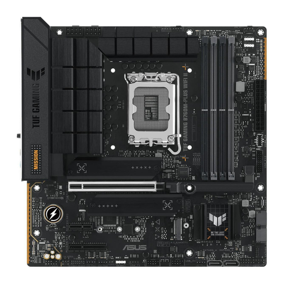
Page 14: Motherboard Layout
Motherboard layout 24.4cm(9.6in) CPU_OPT AIO_PUMP CPU_FAN CPU_12V_2 CPU_12V_1 ADD GEN 2_2 HDMI_DP DIGI+ ADD GEN 2_3 DRAM BOOT USB_E1234 U20G_C1 U10G_3 LAN_U5G_E34 LGA1700 M.2(WIFI) AUDIO 2242 2260 2280 PCIEX16(G5) Ethernet 2280 2260 2242 AURA BATTERY Super Intel ® B760 PCIEX1(G3) 2280 2260 2242... - Page 15 3. Expansion slots This motherboard supports one PCIe x16 graphics card, one PCIe x4, and one PCIe x1 network cards, SCSI cards and other cards that comply with the PCI Express specification. 4. Fan and Pump headers The Fan and Pump headers allow you to connect fans or pumps to FAN PWR FAN IN cool the system.
- Page 16 9. USB 5Gbps header The USB 5Gbps header allows you to connect a USB 5Gbps module for additional USB 5Gbps ports. The USB 5Gbps header provides data transfer speeds of up to 5 Gb/s. 10. USB 2.0 headers The USB 2.0 headers allow you to connect USB modules for additional USB 2.0 ports.
- Page 17 If the steps above do not help, remove the onboard button cell battery and short the two pins again to clear the CMOS RTC RAM data. After clearing the CMOS, reinstall the button cell battery. F_AUDIO 13. Front Panel Audio header The Front Panel Audio header is for a chassis-mounted front panel audio I/O module that supports HD Audio.
- Page 18 15. Thunderbolt™ (USB4 ) header ® TB_HEADER The Thunderbolt™ (USB4 ) header allows you to connect an add-on ® Thunderbolt™ I/O card that supports Intel ’s Thunderbolt™ Technology, ® allowing you to connect Thunderbolt™-enabled devices to form a daisy- chain configuration. Please visit the official website of your purchased add-on card for more PIN 1 details on compatibility.
- Page 19 1.2.2 Rear panel connectors Rear panel connectors DisplayPort USB 2.0 ports E1, E2, E3, E4 USB 10Gbps (Teal blue) Type-A port Realtek 2.5Gb Ethernet port* HDMI™ port USB 20Gbps Type-C port C1 ® USB 5Gbps ports E3, E4 Wi-Fi module Optical S/PDIF out port Audio jacks** * and **: Refer to the tables below for LAN port LEDs, and audio port definitions.
- Page 20 ** Audio 2, 4, 5.1 or 7.1-channel configuration Port 2-channel 4-channel 5.1-channel 7.1-channel Rear panel Side Speaker LINE IN Front Speaker Front Speaker Front Speaker Front Speaker LINE OUT MIC IN Rear Speaker Rear Speaker Rear Speaker REAR Center/ Center/ C/SUB Subwoofer Subwoofer...
-
Page 21: Cpu Installation
Install a heatsink or AIO cooler after installing the CPU. Please refer to the Motherboard Installation Guide on the ASUS support site, or to the user manual of the heatsink/AIO cooler for steps on installing the heatsink/AIO cooler. Take caution when lifting the load lever, ensure to hold onto the load lever when releasing the load lever. - Page 22 Ensure to remove the CPU Socket lever protector on the lever latch before locking the lever latch under the retention tab. Failure to do so may cause damages to your system when installing the cooling system. 1-10 Chapter 1: Product Introduction...
-
Page 23: Dimm Installation
(D/C) from the same vendor. Check with the vendor to get the correct memory modules. • Visit the ASUS website for the latest QVL. Motherboard User Manual 1-11... - Page 24 Installing a DIMM DIMM removal 1-12 Chapter 1: Product Introduction...
-
Page 25: M.2 Module Installation
M.2 module installation • Use a Phillips screwdriver when removing or installing the screws or screw stands mentioned in this section. • If the thermal pad on the M.2 heatsink becomes damaged, we recommend replacing it with a thermal pad with a thickness of 1.25mm. •... - Page 26 OR remove the M.2 rubber. Only follow this step if installing a 2242 length M.2 module and the M.2 slot has an M.2 rubber pre-installed. Install your M.2 to your M.2 slot. Ensure that there is nothing obstructing your M.2 module when installing the M.2 module to the M.2 slot.
- Page 27 For 2242, 2260 length Install the bundled screw stand to the M.2 length screw hole you wish to install your M.2 to. Install your M.2 to the M.2 slot. Secure your M.2 using the bundled screw stand’s screw. Remove the plastic film from the thermal pads on the bottom of the heatsinks. If the thermal pad on the M.2 heatsink becomes damaged, we recommend replacing it with a thermal pad with a thickness of 1.25mm.
-
Page 28: Asus Wifi Q-Antenna Installation
ASUS WiFi Q-Antenna installation Installing the ASUS WiFi Q-Antenna Connect the bundled ASUS WiFi Q-Antenna connector to the Wi-Fi ports at the back of the chassis. • Ensure to hold tightly onto the connector when removing the antenna connector from the Wi-Fi ports, and refrain from attempting to remove the antenna connector from the Wi-Fi ports by pulling on the antenna connector cable. -
Page 29: Knowing Uefi Bios
For more details on BIOS and RAID configurations, please refer to Manual & Document under the Support tab of the product information site, or visit https://www.asus.com/support. Knowing UEFI BIOS BIOS (Basic Input and Output System) stores system hardware settings such as storage device configuration, overclocking settings, advanced power management, and boot device configuration that are needed for system startup in the motherboard CMOS. -
Page 30: Asus Ez Flash 3
ASUS EZ Flash 3 The ASUS EZ Flash 3 feature allows you to update the BIOS without using an OS-based utility. Ensure to load the BIOS default settings to ensure system compatibility and stability. Select the Load Optimized Defaults item under the Exit menu or press the <F5> hotkey. -
Page 31: Asus Crashfree Bios 3
ASUS CrashFree BIOS 3 The ASUS CrashFree BIOS 3 utility is an auto recovery tool that allows you to restore the BIOS file when it fails or gets corrupted during the updating process. You can restore a corrupted BIOS file using a USB flash drive that contains the BIOS file. -
Page 32: Raid Configurations
RAID configurations The motherboard supports SATA RAID configurations. RAID definitions RAID 0 (Data striping) optimizes two identical hard disk drives to read and write data in parallel, interleaved stacks. Two hard disks perform the same work as a single drive but at a sustained data transfer rate, double that of a single disk alone, thus improving data access and storage. -
Page 33: Appendix
Appendix General Notices FCC Compliance Information Responsible Party: Asus Computer International Address: 48720 Kato Rd., Fremont, CA 94538, USA Phone / Fax No: (510)739-3777 / (510)608-4555 This device complies with part 15 of the FCC Rules. Operation is subject to the following two conditions: (1) This device may not cause harmful interference, and (2) this device must accept any interference received, including interference that may cause undesired operation. - Page 34 ASUS products sold in Vietnam, on or after September 23, 2011,meet the requirements of the Vietnam Circular 30/2011/TT-BCT. Các sản phẩm ASUS bán tại Việt Nam, vào ngày 23 tháng 9 năm2011 trở về sau, đều phải đáp ứng các yêu cầu của Thông tư 30/2011/TT-BCT của Việt Nam.
- Page 35 AEEE Yönetmeliğine Uygundur ASUS Recycling/Takeback Services ASUS recycling and takeback programs come from our commitment to the highest standards for protecting our environment. We believe in providing solutions for you to be able to responsibly recycle our products, batteries, other components as well as the packaging materials.
-
Page 36: Notices For Wi-Fi Model
Notices for Wi-Fi model FCC RF Caution Statement WARNING: Any changes or modifications not expressly approved by the party responsible for compliance could void your authority to operate the equipment. FCC 5.925-7.125 GHz Caution Statement Operation of transmitters in the 5.925-7.125 GHz band is prohibited for control of or communications with unmanned aircraft systems. - Page 37 KC: Korea Warning Statement NCC: Wireless Statement 取得審驗證明之低功率射頻器材,非經核准,公司、商號或使用者均不得擅自變更頻 率、加大功率或變更原設計之特性及功能。低功率射頻器材之使用不得影響飛航安全及 干擾合法通信;經發現有干擾現象時,應 立即停用,並改善至無干擾時方得繼續使用。 前述合法通信,指依電信管理法規定作業之無線電通信。低功率射頻器材須忍受合法通 信或工業、科學及醫療用電波輻射性電機設備之干擾。 應避免影響附近雷達系統之操作。 Japan RF Equipment Statement 屋外での使用について 5GHz帯 (W52/53) 及び6GHz帯 (LPI) の屋外での使用は、 電波法により禁じられています (法令により許可され た場合は除く) ( 6GHz帯は対応製品のみ) 。 法律および規制遵守 本製品は電波法及びこれに基づく命令の定めるところに従い使用してください。 日本国外では、 その国の法律 または規制により、 本製品の使用ができないことがあります。 このような国では、 本製品を運用した結果、 罰せ られることがありますが、 当社は一切責任を負いかねますのでご了承ください。 Précautions d’emploi de l’appareil : Soyez particulièrement vigilant quant à...
- Page 38 ASUSTek Computer Inc. hereby declares that this device is in compliance with the essential requirements and other relevant provisions of The Radio Equipment Regulations 2017 (S.I. 2017/1206). Full text of UKCA declaration of conformity is available at https://www.asus.com/support/. The WiFi operating in the band 5150-5350MHz shall be restricted to indoor use for the country listed below:...
- Page 39 декларация за съвместимост е достъпен на адрес der Richtlinie 2014/53/EU übereinstimmt. Der gesamte Text der EU- https://www.asus.com/support/. Konformitätserklärung ist verfügbar unter: https://www.asus.com/support/. WiFi, работеща в диапазон 5150-5350MHz, трябва да се ограничи до Der WLAN-Betrieb im Band von 5150-5350 MHz ist für die in der unteren употреба...
- Page 40 Käesolevaga kinnitab ASUSTek Computer Inc, et seade vastab direktiivi zahtjevima i ostalim odgovarajućim odredbama direktive 2014/53/EU. Cijeli 2014/53/EÜ olulistele nõuetele ja teistele asjakohastele sätetele. EL tekst EU izjave o sukladnosti dostupan je na https://www.asus.com/support/. vastavusdeklaratsiooni täistekst on saadaval veebisaidil https://www.asus.com/support/.
- Page 41 Az EU megfelelőségi nyilatkozat teljes szövegét a ASUSTek Computer Inc. erklærer herved at denne enheten er i samsvar med következő weboldalon tekintheti meg: https://www.asus.com/support/. hovedsaklige krav og andre relevante forskrifter i direktivet 2014/53/EU. Az 5150-5350 MHz-es sávban működő Wi-Fi-t beltéri használatra kell Fullstendig tekst for EU-samsvarserklæringen finnes på:...
- Page 42 Direktive 2014/53/EU. Polno 5150-5350 MHz arasındaki WiFi çalışması, tabloda listelenen ülkeler için iç besedilo izjave EU o skladnosti je na voljo na https://www.asus.com/support/. mekân kullanımıyla kısıtlanacaktır. WiFi, ki deluje v pasovnem območju 5150–5350 MHz, mora biti v državah, Düşük Güç...
- Page 43 ASUSTek Computer Inc. заявляє, що цей пристрій відповідає основним CE RED RF Output table (Directive 2014/53/EU) вимогам та іншим відповідним вимогам Директиви 2014 / 53 / EU. Model: MT7922A22M Повний текст декларації відповідності нормам ЄС доступний на https://www.asus.com/support/. Function Frequency Maximum Output Power (EIRP) Робота...
-
Page 44: Warranty
• ASUS offers a voluntary manufacturer’s Commercial Guarantee. • ASUS dragovoljno nudi komercijalno proizvođačko jamstvo. • ASUS reserves the right to interpret the provisions of the ASUS • ASUS zadržava prava na tumačenje odredbi ASUS komercijalnog Commercial Guarantee. jamstva. •... - Page 45 • ASUS tilbyr som produsent en frivillig kommersiell garanti. • Bảo hành thương mại này của ASUS được cung cấp độc lập và ngoài • ASUS forbeholder seg retten til å tolke bestemmelsene i ASUS sin Bảo đảm pháp lý theo luật định và không có cách nào ảnh hưởng đến kommersielle garanti.
-
Page 46: Asus Contact Information
Address: 1F., No. 15, Lide Rd., Beitou Dist., Taipei City 112 ASUS COMPUTER INTERNATIONAL (America) Address: 48720 Kato Rd., Fremont, CA 94538, USA ASUS COMPUTER GmbH (Germany and Austria) Address: Harkortstrasse 21-23, 40880 Ratingen, Germany ASUSTeK (UK) LIMITED Address: 1st Floor, Sackville House, 143-149 Fenchurch Street, London, EC3M 6BL,...
Need help?
Do you have a question about the TUF GAMING B760M-PLUS WIFI II and is the answer not in the manual?
Questions and answers