Table of Contents
Troubleshooting

Related Manuals for Frymaster BK1814E Series


Summary of Contents for Frymaster BK1814E Series
- Page 1 Frymaster, a member of the Commercial Food Equipment Service Association, recommends using CFESA Certified Technicians. 24-Hour Service Hotline 1-800-551-8633 JUNE 2011 *8196810* www.frymaster.com E-mail: service@frymaster.com...
- Page 2 UNAUTHORIZED SERVICE CENTER. This appliance is intended for professional use only and is to be operated by qualified personnel only. A Frymaster Factory Authorized Servicer (FAS) or other qualified professional should perform installation, maintenance, and repairs. Installation, maintenance, or repairs by unqualified personnel may void the manufacturer’s warranty.
- Page 3 Do not bang fry baskets or other utensils on the fryer’s joiner strip. The strip is present to seal the joint between the fry vessels. Banging fry baskets on the strip to dislodge shortening will distort the strip, adversely affecting its fit.
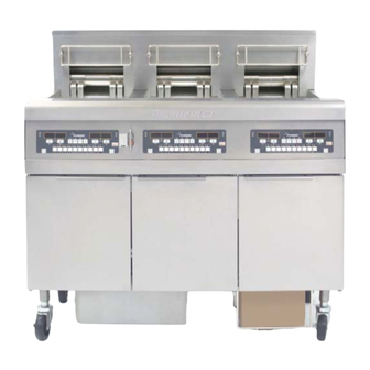
- Page 4 FINDING YOUR WAY AROUND THE FRYMASTER BK1814E SERIES ELECTRIC FRYER Tilt Housing Elements Control Panel (BK 3-Lane Controller Shown) Fuse Drain Handle Fryer Identification Data Labels (Model and Serial Number) TYPICAL CONFIGURATION (BK31814E SHOWN) NOTE: The appearance of your fryer may differ slightly from that shown depending upon the configuration and date of manufacture.
-
Page 5: Table Of Contents
BK1814E SERIES ELECTRIC FRYER Installation and Operation Manual CHAPTER 1: Introduction General Information ... 1-1 Safety Information ... 1-1 Controller Information ... 1-1 European Community (CE) Specific Information ... 1-2 Installation, Operating and Service Personnel ... 1-2 Definitions ... 1-2 Shipping Damage Claim Procedure ... - Page 6 CHAPTER 6: Operator Troubleshooting Introduction ... 6-1 Troubleshooting ... 6-2 6.2.1 Controller and Heating Problems ... 6-2 6.2.2 Troubleshooting Error Messages and Display Problems ... 6-4 6.2.3 Filtration Problems ... 6-4 User Replaceable Parts ... 6-6...
-
Page 7: Chapter 1: Introduction
Read the instructions in this manual thoroughly before attempting to operate this equipment. This manual covers all configurations of BK1814E series electric fryers. The fryers in this model family have most parts in common, and when discussed as a group, will be referred to as “BK1814E” electric fryers. -
Page 8: European Community (Ce) Specific Information
Installation, Operating, and Service Personnel Operating information for Frymaster equipment has been prepared for use by qualified and/or authorized personnel only, as defined in Section 1.6. All installation and service on Frymaster equipment must be performed by qualified, certified, licensed, and/or authorized installation or service personnel, as defined in Section 1.6. -
Page 9: Shipping Damage Claim Procedure
QUALIFIED SERVICE PERSONNEL Qualified service personnel are those who are familiar with Frymaster equipment and who have been authorized by Frymaster, L.L.C. to perform service on the equipment. All authorized service personnel are required to be equipped with a complete set of service and parts manuals, and to stock a minimum amount of parts for Frymaster equipment. -
Page 10: Chapter 2: Installation Instructions
Section 1.6 of this manual) to install or otherwise service this equipment will void the Frymaster warranty and may result in damage to the equipment or injury to personnel. Where conflicts exist between instructions and information in this manual and local or national codes or regulations, installation and operation shall comply with the codes or regulations in force in the country in which the equipment is installed. - Page 11 CE codes. All units (cord connected or permanently connected) should be connected to a grounded power supply system. A wiring diagram is located on the inside of the fryer door. Refer to the rating plate on the inside of the fryer door for proper voltages. 2.1.3 Australian Requirements To be installed in accordance with AS 5601 / AG 601, local authority, gas, electricity, and any other relevant statutory regulations.
-
Page 12: Power Requirements
Positioning the Fryer No structural material on the fryer should be altered or removed to accommodate placement of the fryer under a hood. Questions? Call the Frymaster Service Hotline at 1-800-551-8633. Three (3) Phase Requirements MINIMUM WIRE... - Page 13 1. Once the fryer has been positioned at the frying station, use a carpenter’s level placed across the top of the frypot to verify that the unit is level, both side-to-side and front-to-back. To level fryers, adjust the casters being careful to ensure the fryer(s) are at the proper height in the frying station.
-
Page 14: Chapter 3: Operating Instructions
3. Ensure that the power is switched on. Some models are equipped with a master switch located behind the fryer door cabinet on the front panel of the component box, next to the fuse. See page 3-1. off is displayed on the controller. -
Page 15: Controllers
3. Place the frypot covers on the frypots. 3.2 Controllers Refer to the separate controller manual furnished with your fryer for the specific controller operating instructions. Refer to Chapter 4 of this manual for operating instructions for the built-in filtration system. -
Page 16: Chapter 4: Filtration Instructions
When draining oil into a disposal unit or portable filter unit, do not fill above the maximum fill line located on the container. If your fryer is not equipped with a built-in filtration system, the oil must be drained into another suitable METAL container. (For safe, convenient draining and disposal of used oil or shortening, Frymaster recommends using the Frymaster Shortening Disposal Unit (SDU). -
Page 17: Filter Preparation
Frymaster recommends that a Frymaster filter cone holder and filter cone be used when a filter machine is not available. If you are using a Frymaster filter cone holder, be sure that the cone holder rests securely on the metal container. -
Page 18: Filter Components
4.3.1 Filter Components Filter paper is held in place by a hold-down ring. Oil moves through the paper, leaving behind impurities. Filter pan. Filter support grid. Filter paper. Hold-down ring. Crumb screen. A filter unit which utilizes disposable filter paper to filter oil. -
Page 19: Assembling The Filter
4.3.2 Assembling the Filter 1. Place the support grid in the bottom of filter pan. 2. Put one filter paper sheet on top of the support grid. Be sure the paper covers the filter pan bottom and laps two inches onto the pan wall. 3. - Page 20 4.3.2 Assembling the Filter (cont.) 4. Sprinkle 8 ounces (227g) of filter powder on the filter sheet. Ensure the powder covers the filter paper evenly. 5. Place the crumb screen in the filter pan. Allow the crumb screen to rest on the top edges of the hold-down ring.
-
Page 21: Installing The Filter
4.3.3 Installing the Filter 1. Slide the filter inside the fryer cabinet. Ensure the male-female pickup tubes are fully engaged. Ensure the filter pan opening is directly under the center dump tube. Daily Filter Operation Use caution and wear proper protective clothing. The oil to be filtered is at or near 350°F (177°C). -
Page 22: Filtering Tools
4.4.2 Filtering Tools Assemble tools to be used for filtering. These are supplied with the filter starter kit included with the fryer/filter system: • Frypot/Filter Brush - used to clean frypot and filter pan sides and bottom, heating elements, and to dislodge sediment during filtration or oil change. -
Page 23: Operating The Filter
(~350°F/~177°C). 3. Remove the basket support rack from the frypot using the Fryer’s Friend clean-out rod. Stir the oil with the frypot/filter brush to suspend debris prior to draining. 4. After ensuring the filter pan is correctly... - Page 24 8. After the filter cycle is complete, close the drain valve (push the red handle to the left until it stops) and allow the fryer to refill. 9. After all oil is pumped back into the frypot, bubbles will form, indicating air in the oil return lines.
- Page 25 Some food particles can spontaneously combust if left soaking in certain shortening material. Do not bang fry baskets or other utensils on the fryer’s joiner strip. The strip is present to seal the joint between the fry vessels.
-
Page 26: Draining And Disposing Of Waste Oil
When your oil has reached the end of its usable life, drain the oil into an appropriate METAL container for transport to the disposal container. Frymaster recommends the use of the Frymaster Shortening Disposal Unit (SDU). Refer to the documentation furnished with your disposal unit for specific operating instructions. -
Page 27: Chapter 5: Preventive Maintenance
Clean inside the fryer cabinet with a dry, clean cloth. Wipe all accessible metal surfaces and components to remove accumulated oil and dust. Clean outside the fryer cabinet with a clean, damp cloth soaked with detergent. Wipe with a clean, damp cloth. -
Page 28: Annual/Periodic System Inspection
Annual/Periodic System Inspection This appliance should be inspected and adjusted periodically by qualified service personnel as part of a regular kitchen maintenance program. Frymaster recommends that this appliance be inspected at least annually by a Factory Authorized Servicer as follows: Fryer •... - Page 29 • Verify that all safety features (i.e. contactor shields, drain safety switches, reset switches, etc.) are present and functioning properly. • Verify that the frypot is in good condition and free of leaks and that the frypot insulation is in serviceable condition.
-
Page 30: Chapter 6: Operator Troubleshooting
Although the chapter covers the most common problems reported, you may encounter problems that are not covered. In such instances, the Frymaster Technical Services staff will make every effort to help you identify and resolve the problem. -
Page 31: Troubleshooting
Enter 1751. To enable melt cycle bypass, press the check button with the controller off and enter 1753. This fryer is equipped with a drain safety switch that prevents the heating element from being energized if the drain valve is not fully closed. -
Page 32: Error Messages And Display Problems
Probable Causes Display is in wrong temperature scale Incorrect display option programmed. (Fahrenheit or Celsius). Fryer is more than 21ºF (12ºC) above Display shows HI. setpoint. Frypot temperature is more than Display shows HOT. 410ºF (210ºC) or, in CE countries, 395ºF (202ºC). -
Page 33: Filtration Problems
Filter pump runs but oil does not Test: Close the drain valve and pull return to frypot and the filter pan out from the fryer. there is no bubbling Activate the pump. If bubbling oil oil. occurs, there is a blockage in the filter pan suction tube. -
Page 34: User Replaceable Parts
Problem Probable Causes B. Attempting to filter with oil that is not hot enough. User Replaceable Parts User Replaceable Parts Part Number 230-8464 230-8319 230-8463 230-8462 230-4318 108-1872 806-3068 806-3071 823-5772 823-7619 803-0278 803-0197 Filter Pan Components 823-7425 810-3541 200-8003 108-1582 823-7418 803-0289... - Page 35 THIS PAGE INTENTIONALLY LEFT BLANK...
- Page 36 Frymaster, 8700 Line Avenue, Shreveport, Louisiana 71106 TEL 1-318-865-1711 FAX (Parts) 1-318-688-2200 (Tech Support) 1-318-219-7135 819-6810 SERVICE HOTLINE JUNE 11 PRINTED IN THE UNITED STATES 1-800-551-8633...