Tripp Lite SmartOnline SU20KX Owner's Manual
Smartonline 3-phase ups systems, input/output: 220/380v, 230/400v or 240/415v ac, 3o, 4-wire + ground
Hide thumbs
Also See for SmartOnline SU20KX:
- Owner's manual (74 pages) ,
- Owner's manual (208 pages) ,
- Manual (110 pages)
Table of Contents
Advertisement
Quick Links
Owner's Manual
1
2
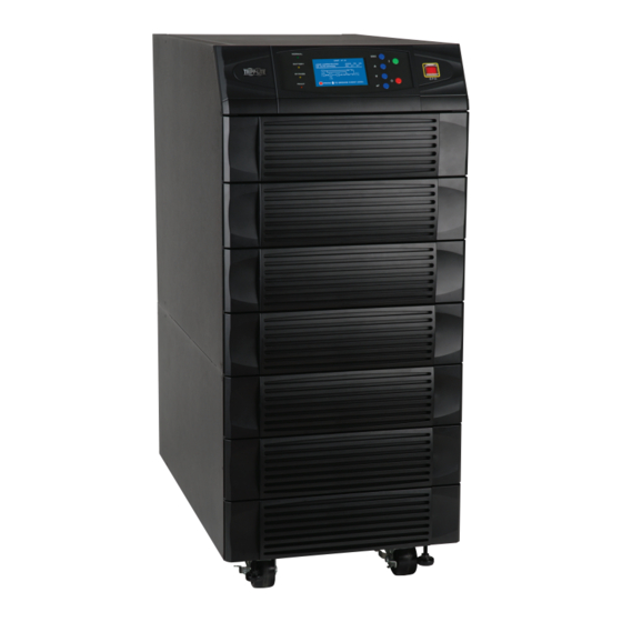
SmartOnline
3-Phase UPS Systems
™
Models: SU20KX, SU40KX, SU60KX, SU80KX
3
Input/Output: 220/380V, 230/400V or 240/415V AC, 3O, 4-wire + ground
Not suitable for mobile applications.
4
5
6
7
8
9
10
11
12
13
1111 W. 35th Street, Chicago, IL 60609 USA
14
www.tripplite.com/support
Copyright © 2010 Tripp Lite. All trademarks are the sole property of their respective owners.
1
Advertisement
Table of Contents


Need help?
Do you have a question about the SmartOnline SU20KX and is the answer not in the manual?
Questions and answers