
Related Manuals for UNI-T UT58E


Summary of Contents for UNI-T UT58E
-
Page 1: Table Of Contents
Model UT58E: OPERATING MANUAL Table of Contents Title Page Overview Unpacking Inspection Safety Information Rules For Safe Operation International Electrical Symbols The Meter Structure Rotary Switch Functional Buttons Display Symbols Measurement Operation A. DC and AC Voltage Measurement B. DC and AC Current Measurement C. -
Page 2: Title Page
Model UT58E: OPERATING MANUAL Title Page Maintenance A. General Services B. Replacing the Fuses C. Replacing the Battery... -
Page 3: Overview
To avoid electric shock or personal injury, read the “Safety Information” and “Rules for Safety Operation” carefully before using the Meter. Digital Multimeters Model UT58E (hereafter referred to as “the Meter”) is 4 1/2 digits with ex-large LCD, steady operations, fashionable structure and highly reliable hand-held measuring instrument. -
Page 4: Unpacking Inspection
Model UT58E: OPERATING MANUAL Unpacking Inspection Open the package case and take out the Meter. Check the following items carefully to see any missing or damaged part: Item Description English Operating Manual 1 piece Test Lead 1 pair Multi-Purpose Socket... -
Page 5: Safety Information
Model UT58E: OPERATING MANUAL Safety Information This Meter complies with the standards IEC61010: in pollution degree 2, overvoltage category (CAT. II 1000V, CAT. III 600V) and double insulation. CAT. II: Local level, appliance, PORTABLE EQUIPMENT etc., with smaller transient voltage overvoltages than CAT. -
Page 6: Rules For Safe Operation
Model UT58E: OPERATING MANUAL Rules For Safe Operation (1) Warning To avoid possible electric shock or personal injury, and to avoid possible damage to the Meter or to the equipment under test, adhere to the following rules: Before using the Meter inspect the case. Do not use the Meter if it is damaged or the case (or part of the case) is removed. - Page 7 Model UT58E: OPERATING MANUAL Rules For Safe Operation (2) l When using the test leads, keep your fingers behind the finger guards. l Disconnect circuit power and discharge all high -voltage capacitors before testing resistance, continuity, diodes, capacitance or current.
-
Page 8: International Electrical Symbols
Model UT58E: OPERATING MANUAL International Electrical Symbols AC (Alternating Current). DC (Direct Current). Grounding. Double Insulated. Deficiency of Built-In Battery. Warning. Refer to the Operating Manual. Diode. Fuse. Continuity Test. Conforms to Standards of European Union. -
Page 9: The Meter Structure
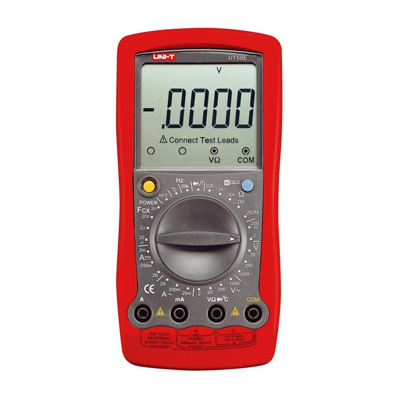
Model UT58E: OPERATING MANUAL The Meter Structure (see figure 1) ( figure 1) 1 LCD Display 2 HOLD Button. 3 Rotary Switch 4 COM Input Terminal 5 POWER 6 Other Input Terminal. 7 mA Input Terminal 8 20A Input Terminal... -
Page 10: Rotary Switch
Model UT58E: OPERATING MANUAL Rotary Switch Below table indicated for information about the rotary switch positions. DC voltage measurement. AC voltage measurement. Transistor Test AC Current Measurement DC Current Measurement Capacitance Test Temperature Measurement Frequency Measurement Diode test Continuity test... -
Page 11: Functional Buttons
Model UT58E: OPERATING MANUAL... -
Page 12: Display Symbols
Model UT58E: OPERATING MANUAL Display Symbols(1) (see figure 2) ( figure 2) Symbol Meaning The battery is low. Warning: To avoid false readings, replace the battery as soon as the battery indicator appears. Warning Symbol. Indicator for AC voltage or current. - Page 13 Model UT58E: OPERATING MANUAL Display Symbols(2) (see figure 2) Symbol Meaning The Unit of Transistor Test Volts. The unit of voltage. mV: Millivolt. 1 x 10 or 0.001 volts. A: Amperes (amps). The unit of current. mA: Milliamp. 1 x 10 or 0.001...
-
Page 14: Measurement Operation
Model UT58E: OPERATING MANUAL Measurement Operation(1) To avoid harms to you or damages to the Meter from electric shock, never attempt to measure voltages higher than 1000 or 1000V rms although readings may be obtained. Black ( figure 3) -
Page 15: Dc And Ac Current Measurement
Model UT58E: OPERATING MANUAL Measurement Operation(2) “ ” B. DC and AC Current Measurement (see figure 4) Black ( figure 4) - Page 16 Model UT58E: OPERATING MANUAL Measurement Operation(3) Warning Never attempt an in-circuit current measurement where the open circuit voltage between terminals and ground is greater than 60V DC or 30V rms in AC. If the fuse burns out during measurement, the Meter may be damaged or the operator himself may be hurt.
-
Page 17: Measuring Resistance
Model UT58E: OPERATING MANUAL Measurement Operation(4) Note l If the value of current to be measured is unknown, use the maximum measurement position, and reduce the range step by step until a satisfactory reading is obtained. l For safety sake, the measuring time for high current... -
Page 18: Measuring Diodes And Continuity
Model UT58E: OPERATING MANUAL Measurement Operation(5) To measure resistance, connect the Meter as follows: “1” D. Measuring Diodes and Continuity (see figure 6) Black ( figure 6) - Page 19 Model UT58E: OPERATING MANUAL Measurement Operation(6) Warning To avoid damage to the Meter or to the equipment under test, disconnect circuit power and discharge all high-voltage capacitors before measuring diodes. To avoid harms to you, never attempt to input voltages...
-
Page 20: Frequency Measurement
Model UT58E: OPERATING MANUAL Measurement Operation(7) l The open-circuit voltage is around 3V. l When diode testing has been completed, disconnect the connection between the testing leads and the circuit under test, and remove the testing leads away from the input terminal of the Meter. -
Page 21: Temperature Measurement
Model UT58E: OPERATING MANUAL Measurement Operation(8) Note l When Hz measurement has been completed, disconnect the connection between the testing leads and the circuit under test, and remove the testing leads away from the input terminals of the Meter. Temperature Measurement... - Page 22 Model UT58E: OPERATING MANUAL Measurement Operation(9) Warning To avoid harm to you or damages to the Meter, never attempt to measure voltages higher than 60V in DC or 30V rms in AC although readings may be obtained. During testing, the operating temperature must be...
-
Page 23: Capacitance Measurement
Model UT58E: OPERATING MANUAL Measurement Operation(10) G. Capacitance Measurement (see figure 9) ( figure 9) Warning To avoid damage to the Meter or to the equipment under test, disconnect circuit power and discharge all high-voltage capacitors before measuring capacitance.Use the DC voltage function to confirm that the capacitor is discharged. - Page 24 Model UT58E: OPERATING MANUAL Measurement Operation(11) Note l If the value of capacitance to be measured is unknown, use the maximum measurement position, and reduce the range step by step until a satisfactory reading is obtained. l When the tested capacitor is shorted or the capacitor value is overloaded, the LCD display “1”.
-
Page 25: Measuring Transistor
Model UT58E: OPERATING MANUAL Measurement Operation(12) H. Measuring Transistor (see figure 9) Warning To avoid harms to you, please do not attempt to input voltages higher than 60V DC or 30V rms AC. To measure transistor, connect the Meter as follows: 1. -
Page 26: Sleep Mode
Model UT58E: OPERATING MANUAL Sleep Mode To preserve battery life, the Meter automatically turns off if you do not turn the rotary switch or press any button for around 15 minutes. When the Meter is under sleep mode, it consumes 10 A current. -
Page 27: General Specifications
Model UT58E: OPERATING MANUAL General Specifications 0.5A, 250V fast type, 5x20mm. C input jack’s fuse:0.63A,250V fast type, 5x20mm, to be used on capacitance,temperature and transistor testing input protection. 20A Input Terminal : Unfused. l Maximum Display : 19999,updates 2~3 times/second. -
Page 28: Accuracy Specifications
Model UT58E: OPERATING MANUAL... -
Page 29: Ac Current
Model UT58E: OPERATING MANUAL... -
Page 30: Diodes And Continuity Test
Model UT58E: OPERATING MANUAL Accuracy Specifications(3) -
Page 31: Temperature
Model UT58E: OPERATING MANUAL Accuracy Specifications(4) Temperature ±(3%+40) ±(1%+30) ±(2%+50) I. Capacitance J. Transistor test Overload Testing Protection Conditions 250V rms... -
Page 32: Maintenance
Model UT58E: OPERATING MANUAL Maintenance(1) This section provides basic maintenance information including battery and fuse replacement instruction. Warning Do not attempt to repair or service your Meter unless you are qualified to do so and have the relevant calibration, performance test, and service information. -
Page 33: C. Replacing The Battery
Model UT58E: OPERATING MANUAL Maintenance(2) Warning To avoid electrical shock or arc blast, or personal injury or damage to the Meter, use specified fuses ONLY in accordance with the following procedure. To replace the Meter’s fuse: 1. Turn the Meter off and remove all connections from the terminals. - Page 34 Model UT58E: OPERATING MANUAL Maintenance(3) 3. Remove the 3 screws from the case bottom, and separate the case top from the case bottom. 4. Remove the battery from the battery connector. 5. Replace with a new 9V battery (NEDA1604, 6F22 or 006P).
- Page 35 Model UT58E: OPERATING MANUAL...
- Page 36 Model UT58E: OPERATING MANUAL Copyright 2001 Uni-Trend International Limited. All rights reserved. Manufacturer: UNI-TREND TECHNOLOGY(DONG GUAN)LIMITED Address: Dong Fang Da Dao, Bei Shan Dong Fang Industrial Development District, Hu Men Town, Dong Guan City, Guang Dong Province, China Headquarters: Uni-Trend International Limited...
Need help?
Do you have a question about the UT58E and is the answer not in the manual?
Questions and answers