
Related Manuals for UNI-T UT58A


Summary of Contents for UNI-T UT58A
-
Page 1: Table Of Contents
Model UT58A/B/C: OPERATING MANUAL Table of Contents Title Page Overview Unpacking Inspection Safety Information Rules For Safe Operation International Electrical Symbols The Meter Structure Rotary Switch Functional Buttons Display Symbols Measurement Operation A. DC and AC Voltage Measurement B. DC and AC Current Measurement C. -
Page 2: Title Page
Model UT58A/B/C: OPERATING MANUAL Title Page K. Frequency (UT58C only) Maintenance A. General Services B. Replacing the Fuses C. Replacing the Battery... -
Page 3: Overview
To avoid electric shock or personal injury, read the “Safety Information” and “Rules for Safety Operation” carefully before using the Meter. Digital Multimeters Model UT58A, UT58B and UT58C (hereafter referred to as “the Meter”) are 3 1/2 digits with ex-large LCD, steady operations, fashionable structure and highly reliable hand-held measuring instrument. -
Page 4: Unpacking Inspection
Model UT58A/B/C: OPERATING MANUAL Unpacking Inspection Item Description English Operating Manual 1 piece Test Lead 1 pair Multi-Purpose Socket 1 piece Point Contact Temperature Probe 1 piece (UT58B/UT58C only) 9V Battery (NEDA 1604, 6F22 or 009P) 1 piece In the event you find any missing or damage, please... -
Page 5: Safety Information
Model UT58A/B/C: OPERATING MANUAL Safety Information This Meter complies with the standards IEC61010: in pollution degree 2, overvoltage category (CAT. II 1000V, CAT. III 600V) and double insulation. CAT. II: Local level, appliance, PORTABLE EQUIPMENT etc., with smaller transient voltage overvoltages than CAT. -
Page 6: Rules For Safe Operation
Model UT58A/B/C: OPERATING MANUAL Rules For Safe Operation (1) Warning To avoid possible electric shock or personal injury, and to avoid possible damage to the Meter or to the equipment under test, adhere to the following rules: l Before using the Meter inspect the case. Do not use the Meter if it is damaged or the case (or part of the case) is removed. - Page 7 Model UT58A/B/C: OPERATING MANUAL Rules For Safe Operation (2) l When using the test leads, keep your fingers behind the finger guards. l Disconnect circuit power and discharge all high -voltage capacitors before testing resistance, continuity, diodes, capacitance or current.
-
Page 8: International Electrical Symbols
Model UT58A/B/C: OPERATING MANUAL International Electrical Symbols AC (Alternating Current). DC (Direct Current). Grounding. Double Insulated. Deficiency of Built-In Battery. Warning. Refer to the Operating Manual. Conforms to Standards of European Union. -
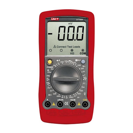
Page 9: The Meter Structure
Model UT58A/B/C: OPERATING MANUAL The Meter Structure (see figure 1) (figure 1) 1. LCD Display. 2. HOLD Button. 3. Rotary Switch. 4. Input Terminals. 5. POWER... -
Page 11: Functional Buttons
Model UT58A/B/C: OPERATING MANUAL Functional Buttons Below table indicated for information about the functional button operations. Button Operation Performed Turn the Meter on and off. POWER (Yellow l Press down the POWER to turn on Button) the Meter. l Press up the POWER to turn off the Meter. -
Page 12: Display Symbols
Model UT58A/B/C: OPERATING MANUAL FmVV k M nF FkHz AmAA Connect Test Leads (figure 2) Symbol Meaning The battery is low. Warning: To avoid false readings, replace the battery as soon as the battery indicator appears. Indicator for AC voltage or current. - Page 13 Model UT58A/B/C: OPERATING MANUAL Symbol Meaning ,k ,M mV, V F nF A, mA, A...
-
Page 14: Measurement Operation
To measure DC or AC Voltage, connect the Meter as follows: 1. Insert the red test lead into the HzV (UT58C) or (UT58A/UT58B) terminal and the black test lead into the COM input terminal. 2. Set the rotary switch to an appropriate measurement... -
Page 15: Dc And Ac Current Measurement
Model UT58A/B/C: OPERATING MANUAL Measurement Operation(2) black (figure 4) Warning Never attempt an in-circuit current measurement where the open circuit voltage between terminals and ground is greater than 250V . If the fuse burns out during measurement, the Meter may be damaged or the operator himself may be hurt. - Page 16 To measure current, do the following: 1. Turn off power to the circuit. Discharge all high- voltage capacitors. 2. Insert the red test lead into the A or AmA ( UT58A) or mA (UT58B/UT58C) terminal and the black test lead into the COM terminal.
-
Page 17: Measuring Resistance
Model UT 58C:200 , 2k , 20k , 2M and 20M . 1. Insert the red test lead into the Hz V (UT58C) or (UT58A/UT58B) terminal and the black test lead into the COM terminal. 2. Set the rotary switch to an appropriate measurement position in range. - Page 18 Model UT58A/B/C: OPERATING MANUAL Note l The test leads can add 0.1to 0.2 of error to the slow- resistance measurement. To obtain accurate readings in low-resistance, short-circuit the input terminals beforehand and record the reading obtained (called this reading as X). (X) is the additional resistance from the test lead.
-
Page 19: Measuring Diodes
To test out a diode out of a circuit, connect the Meter as follows: 1. Insert the red test lead into the Hz V (UT58C) or (UT58A/UT58B) terminal and the black test lead into the COM terminal 2. Set the rotary switch to 3. For forward voltage drop readings on any semiconductor component, place the red test lead on the component’s... -
Page 20: Testing For Continuity
To test for continuity, connect the Meter as below: 1. Insert the red test lead into Hz V (UT58C) or (UT58A/UT58B) terminal and the black test lead into the COM terminal. 2. Set the rotary switch to 3. Connect the test leads across with the object being measured. - Page 22 Model UT58A/B/C: OPERATING MANUAL (figure 9)
-
Page 23: Measuring Transistor
Model UT58A/B/C: OPERATING MANUAL... -
Page 24: Frequency Measurement (Ut58C Only)
Model UT58A/B/C: OPERATING MANUAL POWER... -
Page 25: Operation Of Hold Mode
Model UT58A/B/C: OPERATING MANUAL... -
Page 26: General Specifications
Model UT58A/B/C: OPERATING MANUAL General Specifications Maximum Voltage or Current between input Terminals and Grounding: According to different functional input protection value. Fused Protection for l AmA Input Terminal : CE Version: 0.5A, 250V fast type, 5x20mm. l Maximum Display : 1999,updates 2~3 times/ second. -
Page 27: Accuracy Specifications
Model UT58A/B/C: OPERATING MANUAL Accuracy Specifications(1) Accuracy: (a% reading + b digits),guarantee for 1 year. Operating temperature:18 C~28 Relative humidity: 75%RH. A. DC Voltage Overload Accuracy Range Resolution Protection 250VAC 0.1mV 200mV (0.5%+1) 10mV 1000V AC 100mV 200V 1000V (0.8%+2) Remarks:Input Impedance: approx.10M . -
Page 28: Dc Current
Model UT58A/B/C: OPERATING MANUAL Accuracy Specifications(2) C. DC Current Overload Range Resolution Accuracy Model Protection 20 A 0.01 A UT58A Fuse 0.5A, 250V, (0.8%+1) UT58ABC fast type, 20mA 10 A 5x20mm UT58AB (1.5%+1) 200mA 0.1mA UT58ABC 10mA (2%+5) Un-Fused UT58ABC... -
Page 29: Resistance Test
UT58ABC UT58ABC UT58ABC UT58ABC UT58ABC UT58AB... -
Page 30: Capacitance
Model UT58A/B/C: OPERATING MANUAL Accuracy Specifications(4) H. Capacitance Accuracy Range Resolution (4.0%+3) 200nF 0.1nF ±(5.0%+4) 100 F 0.1 F When it is 40 F: the obtained reading is only for reference Accuracy Range Resolution... -
Page 31: Transistor Test
Model UT58A/B/C: OPERATING MANUAL Accuracy Specifications(5) J. Transistor test Range Resolution Accuracy±(a% reading + b digits) Vce 3V Ibo 10 A 1000 MAX K. Frequency ( UT58C only) Overload Accuracy Range Resolution Protection 2kHz ±(1.5%+5) 250V AC 20kHz 10Hz... -
Page 32: Maintenance
Model UT58A/B/C: OPERATING MANUAL Maintenance(1) This section provides basic maintenance information including battery and fuse replacement instruction. Warning Do not attempt to repair or service your Meter unless you are qualified to do so and have the relevant calibration, performance test, and service information. -
Page 33: C. Replacing The Battery
Model UT58A/B/C: OPERATING MANUAL Maintenance(2) To replace the Meter’s fuse: 1. Turn the Meter off and remove all connections from the terminals. 2. Remove the holster from the Meter. 3. Remove the 3 screws from the case bottom, and separate the case top from the case bottom. - Page 34 Model UT58A/B/C: OPERATING MANUAL ** END ** This operating manual is subject to change without notice.
- Page 35 Model UT58A/B/C: OPERATING MANUAL...
- Page 36 Model UT58A/B/C: OPERATING MANUAL Copyright 2001 Uni-Trend Group Limited. All rights reserved. Manufacturer: Uni-Trend Technology (Dongguan) Limited Dong Fang Da Dao Bei Shan Dong Fang Industrial Development District Hu Men Town, Dongguan City Guang Dong Province China Postal Code: 523 925...
Need help?
Do you have a question about the UT58A and is the answer not in the manual?
Questions and answers