Bacharach LEAKATOR 10 Instructions Manual
Combustible gas detector
Hide thumbs
Also See for LEAKATOR 10:
- Manual (29 pages) ,
- Instructions manual (29 pages) ,
- Instruction manual (24 pages)

Related Manuals for Bacharach LEAKATOR 10


Summary of Contents for Bacharach LEAKATOR 10
- Page 1 LEAKATOR ® INSTRUCTION 0019-9167 COMBUSTIBLE GAS DETECTOR Part No. 0019-7051 Rev. 18 – October 2012...
- Page 2 Bacharach’s option, of this Product or parts thereof returned to Seller at the factory of manufac ture and shown to Bacharach Inc.’s reasonable satisfaction to have been defective; provided that written notice of the defect shall have been given by Buyer to Bacharach Inc.
- Page 3 1-800-736-4666. WARNING! The Leakator 10 is not to be used in any application that is beyond its intended purpose or beyond the scope of its specifi cations. Failure to follow this warning can result in personal injury or damage to the equipment.
-
Page 4: Table Of Contents
5.2 Replacing the Printed Circuit Board ..... 12 5.3 Replacing the Speaker ........13 5.4 Replacing the Flexible Probe Assembly ..14 6.0 TROUBLESHOOTING ..........16 7.0 PARTS/SERVICE............17 7.1 Parts List ............17 7.2 Bacharach Sales/Service Centers ....20 8.0 DECLARTION OF CONFORMITY ......21 Instruction 0019-9167... -
Page 5: Introduction
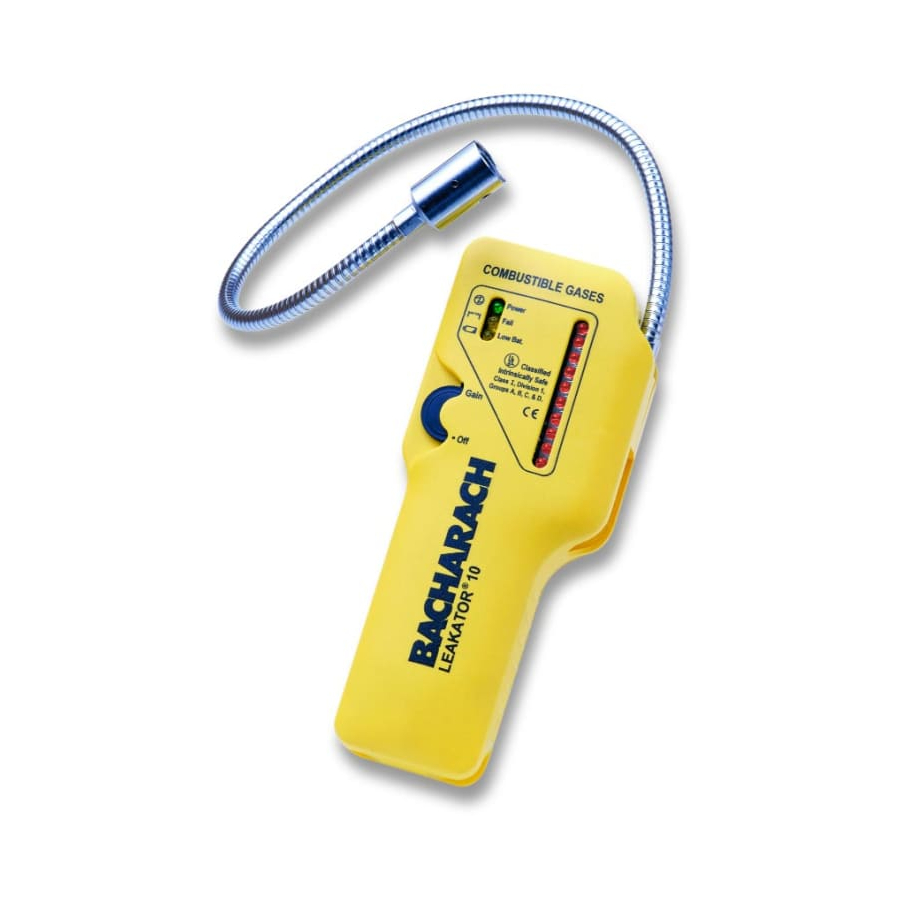
Leakator 10 Introduction 1.0 GENERAL DESCRITPION AND USE The Leakator 10 is an intrinsically safe, battery-powered portable instrument designed to primarily detect the source of combustible-gas leaks. The instrument is ideally suited for heating service contractors, utility personnel, and other... - Page 6 Naphtha Butane Hydrogen WARNINGS! For safety reasons, the Leakator 10 must only be operated and serviced by qualifi ed personnel. Read and understand the contents of this instruction manual before operating or servicing. To prevent ignition of a hazardous atmosphere, do not perform any maintenance work, such as replacing the in- strument’s batteries, sensor, or sensor-matching resistor,...
-
Page 7: Technical Characteristics
Leakator 10 Technical Characteristics 2.0 TECHNICAL CHARACTERISTICS Power ......Five C-size Alkaline Batteries. Battery Life ....Approximately 30 hours of contin- uous operation under normal-use conditions. Sensor: Type ......Solid State, plug-in replacement. Life Expectancy ..Typically 5 years. Calibration ....No user calibration required. -
Page 8: Operating Environment
Leakator 10 Technical Characteristics Weight ......17.8 oz (0.5 kg) (w/o batteries) Dimensions: ....8.5" x 2.25" x 1.75" (21.6 x 5.7 x 4.4 cm) Operating Environment: Position ....Any Temperature ..23° to 130°F (–5° to 54°C) Humidity ....10% to 90% RH, non-condensing Safety Approvals ..Intrinsically Safe for use in Class... - Page 9 Leakator 10 Battery Installation (Fig 3) clockwise until a click is heard. Observe the following: • The Power LED lights. • The Fail LED will light, but should turn off in a few sec- onds if the sensor is good and properly seated in its socket.
-
Page 10: Taking A Gas Reading
Leakator 10 Operation 4.2 Taking a Gas Reading To verify that the instrument is operating, sample a known combustible gas (e.g., a gas-air mixture from an unlit burner of a natural-gas range). If no response is observed or heard, refer to Section 6.0 Troubleshooting. - Page 11 Leakator 10 Operation COMBUSTIBLE GASES Powe r Fail Low Bat. Figure 3. Jack, Control, and Indicators Instruction 0019-9167...
-
Page 12: Using The Earphone
4.3 Using the Earphone The earphone is an optional accessory that provides private monitoring of the Leakator 10, and is recommended for use in high-noise environments. The earphone plugs into the side of the instrument, just above the thumb-wheel control. -
Page 13: Maintenance
Leakator 10 Maintenance 5.1 Replacing the Sensor Replacement sensors are classifi ed at the factory according to sensitivity, and are shipped with a matching resistor that ensures the sensor will function properly when installed in your instrument. It is important that the sensor and its resistor be used together –... -
Page 14: Replacing The Printed Circuit Board
Leakator 10 Maintenance 5.2 Replacing the Printed Circuit Board Items required: • Medium fl at-blade screwdriver • Medium Phillips screwdriver • Replacement printed circuit board (P/N 0019-0418) Procedure: (See Figure 7) 1. Turn OFF instrument and lay it face down on work area. - Page 15 Leakator 10 Maintenance Figure 5. Location of Matching Resistor FORM CLIP (2 ENDS) NOTE: Figure 6. Cutting and Bending Resistor Leads using Forms Molded into Battery Cover Instruction 0019-9167...
-
Page 16: Replacing The Speaker
Leakator 10 Maintenance 9. Install fl exible arm assembly and rear case using the screws that were removed in Step 4. 10. Replace sensor-matching resistor. 11. Replace batteries and battery cover. 12. Test instrument response (refer to Section 4.2). 5.3 Replacing the Speaker Items required: •... -
Page 17: Replacing The Flexible Probe Assembly
Leakator 10 Maintenance 7. Replace fl exible arm assembly and rear case using the screws that were removed in Step 3. 8. Replace sensor-matching resistor. 9. Replace batteries and battery cover. 10. Test instrument response (refer Section 4.2). 5.4 Replacing the Flexible Probe Assembly Items required: •... - Page 18 Leakator 10 Maintenance 9. Plug connector on new fl exible probe assembly into printed circuit board connector J3. 10. Replace printed circuit board, new fl exible probe assembly, and rear case using the screws that were removed in Step 11. Replace sensor.
-
Page 19: Troubleshooting
WARNING! Do not perform any maintenance work in a hazardous area. Because of the Leakator 10’s advanced design, trouble with the instrument can usually be diagnosed by looking at the LEDs as seen through the front-case. See Figure 3. If the Fail LED lights, check that the sensor is seated and J3 is connected to the printed circuit board. -
Page 20: Parts/Service
Leakator 10 Troubleshooting 7.0 PARTS/SERVICE 7.1 Parts List Replacement Parts (See Fig 7) Item Description Part No. Battery Cover (2 Screws)* 0019-0405 Nut, Palnut Fastner 0102-3736 Flexible Probe Assembly (4 Wire)** 0019-3091 Front Case 0019-0392 Printed Circuit Board Assembly 0019-0418... -
Page 21: Bacharach Sales/Service Centers
Leakator 10 Parts & Service 7.2 Bacharach Sales/Service Centers United States Bacharach, Inc. 621 Hunt Valley Circle New Kensington, PA 15068 Phone: 1-800-736-4666 Fax: 724-334-5723 Email: help@mybacharach.com Canada Bacharach of Canada, Inc. 20 Amber St. Unit #7 Markham, Ontario L3R SP4... - Page 22 Leakator 10 Parts & Service Figure 7. Leakator 10 Part Locations (Sheet 1 of 2) Instruction 0019-9167...
- Page 23 Leakator 10 Parts & Service Figure 7. Leakator 10 Part Locations (Sheet 2 of 2) Instruction 0019-9167...
- Page 24 Leakator 10 Parts & Service Instruction 0019-9167...
-
Page 25: Declaration Of Conformity
Gases, Toxic Gases, or Oxygen Signature: __________________________ Name: Doug Keeports Title: VP of Product Development Date: 26 October 2010 The technical documentation fi le required by this directive is maintained at the corporate headquarters of Bacharach, Inc. Instruction 0019-9167... - Page 26 Notes Leakator 10...
- Page 27 Leakator 10 Notes...
- Page 28 Bacharach, Inc. 621 Hunt Valley Circle, New Kensington, PA 15068 Ph: 724-334-5000 • Fax: 724-334-5001 • Toll Free: 800-736-4666 Website: www.mybacharach.com • E-mail: help@mybacharach.com Printed in U.S.A. ® Registered Trademarks...
Need help?
Do you have a question about the LEAKATOR 10 and is the answer not in the manual?
Questions and answers