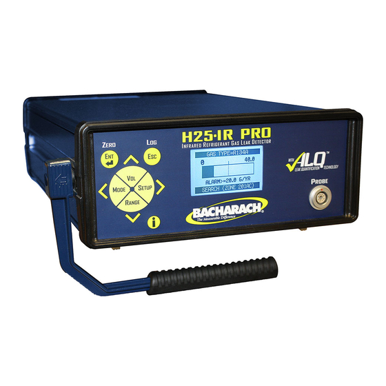
Bacharach H25-IR Operation & Maintenance Manual
Infrared refrigerant gas leak detector
Hide thumbs
Also See for H25-IR:
- Specifications (2 pages) ,
- Product catalog (52 pages) ,
- Instruction (4 pages)

Related Manuals for Bacharach H25-IR


Summary of Contents for Bacharach H25-IR
- Page 1 H25-IR Infrared Refrigerant Gas Leak Detector Instruction 3015-5286 Operation & Maintenance Rev. 4 – December 2010 Product Leadership • Training • Service • Reliability...
- Page 2 Bacharach, Inc. warrants to Buyer that it will convey good title to this Product. Bacharach's liability and Buyer's remedy under this warranty of title are limited to the removal of any title defects or, at the election of Bacharach, to the replacement of this Product or parts thereof that are defective in title.
-
Page 3: Table Of Contents
H25-IR Contents Table of Contents Introduction ..........................1 1.1 Purpose of Instruction Manual ......................1 1.2 Safety Precautions..........................1 1.2.1 Warning Statements......................1 1.2.2 Caution Statements ......................1 1.2.3 Hazard Symbols ........................1 1.2.4 AC Power and Grounding.....................1 1.2.5 Explosive Atmosphere ......................2 1.2.6 Accessing the Interior of the Instrument ................2 1.2.7 Misuse and Modifications to Instrument ................2... - Page 4 3.5 Restoring Factory Calibration ......................27 3.6 Storing a New Factory Calibration ....................27 Operation............................29 4.1 Instrument Location ......................... 29 4.2 Using the H25-IR ..........................29 4.2.1 Power ........................... 29 4.2.2 Initial Setup ........................29 4.2.3 Range Selection........................30 4.2.4 Setup Selection ........................30 4.2.5 Volume Adjustment ......................
- Page 5 H25-IR Contents 5.4.5.5 Factory Calibration ..................52 5.5 Replacement Parts..........................53 Replacement Parts .........................53 Item Description ..........................53 Part Number ...........................53 5.6 Service Centers ..........................54 Troubleshooting ........................55 Specifications..........................61 APPENDIX A – Factory Defaults ....................63 Instruction 3015-5286...
- Page 6 Contents H25-IR Notes: Instruction 3015-5286...
-
Page 7: Introduction
1.2.4 AC Power and Grounding The H25-IR uses a universal power supply that is capable of accepting inputs of 100 to 240 VAC, 50/60 Hz. Under no circumstances should this instrument be operated without connection to a protective ground. Doing so creates a potential shock hazard and is also a violation of electrical safety standards applicable to this type of equipment. -
Page 8: Explosive Atmosphere
1.2.7 Misuse and Modifications to Instrument The operation of the H25-IR may be impaired if the instrument is used in a manner not specified in this instruction manual. Changes or modifications to the instrument, not expressly approved by Bacharach, will void the warranty. -
Page 9: Ordering Information
H25-IR Introduction 1.3 Ordering Information The H25-IR instrument along with its Probe type and Hose length are ordered by specifying 3 codes. The codes must be listed in the following sequence: Code A – Model Name Code B – Gas Type Code C –... -
Page 10: Features And Capabilities
Introduction H25-IR 1.5 Features and Capabilities Detects and measures (depending on instrument’s part number): CFCs, HCFCs, HFCs and halogens R600a Infrared detector Internal calibration leak standard Provision for external calibration on other types of gases ... -
Page 11: Functional Overview
H25-IR Introduction 1.6 Functional Overview The H25-IR is an industrial gas leak analyzer for the detection of CFCs, HCFCs, HFCs and halogen gas compounds, R600a, SF , or CO . This instrument can be used to locate and then quantify gas leaks, as well as log and totalize a group of leaks in a system. -
Page 12: Names And Functions Of Components
Introduction H25-IR 1.7 Names and Functions of Components 1.7.1 Front View Front Panel Buttons • Selects a highlighted menu item. (Enter) • Saves a selection or manually entered data (e.g. date and time). • Displays a previously viewed menu or data screen. -
Page 13: Rear View
H25-IR Introduction 1.7.2 Rear View CONNECTOR for battery cable (on dual power only) 1.7.3 Interior Instruction 3015-5286... -
Page 14: Standard Probe With Led And Programmable Pushbutton
Introduction H25-IR 1.7.4 Standard Probe with LED and Programmable Pushbutton FLEXIBLE PROBE TUBE 8 inches (203 mm) PROBE TIP with FILTER HOSE PROGRAMMABLE PUSHBUTTON 6 or 12 foot (Can be programmed to either zero (Flash rate increases as (1.8 or 3.7 m) -
Page 15: Smart Probe Keylock Function
H25-IR Introduction 1.7.6 Smart Probe Keylock Function The Smart Probe’s keypad can be locked to prevent accidental key presses when working in tight spaces. Instruction 3015-5286... -
Page 16: Menu System
Introduction H25-IR 1.8 Menu System Press the ENT and ESC keys at the same time to access the Main menu. The menu system enables the operator to perform such functions as setting up the instrument, viewing logged readings, configuring the four user-defined setups, entering calibration data, and viewing the instrument’s diagnostic readings. -
Page 17: Preparing For Operation
2.2 Connecting the AC Power Cord Dependent on the instrument model the H25-IR may use an AC power cord or a battery pack. Reference your model number to obtain this information. Disregard any information that does not apply to your model. -
Page 18: Turning On The Instrument
Graphical Display of Relative Gas Level 2.4 System Setup When shipped from the factory, the H25-IR has been configured according to its part number as described in Appendix “A”. To change any of the instrument’s system parameters, first enter System Setup by pressing both the ENT and ESC buttons on either the instrument’s front panel or Smart probe at the same time to display the... -
Page 19: Gas Type
H25-IR Preparing for Operation 2.4.1 Gas Type GAS TYPE < R134A R401A R402A < R402B The GAS TYPE function displays a list of gases that the instrument is programmed to monitor. Refer to Section 6 for a complete list of these gases. -
Page 20: Ma Loop
Preparing for Operation H25-IR For example: If Relay 1 is programmed to “CLOSE AT LOG LIMIT,” its N.O. contacts can be connected to an external alarm device (e.g. strobe light or buzzer) that will activate when the total accumulated leak value in the data log has reached its programmed limit. -
Page 21: Serial Output
H25-IR Preparing for Operation 2.4.8 Serial Output Leak rate data can be output as ASCII text in two formats. <CLOCK SERIAL OUTPUT TYPE PCHK MODE NONE SERIAL OUTPUT TEXT PACKET <PROBE BUTTON TEXT ONLY After selecting the SERIAL OUTPUT function, the user can choose to have the text output to a file in two formats. -
Page 22: Setup Name
Preparing for Operation H25-IR From the Setups menu, use the Up and Down buttons to highlight the desired Setup. Press ENT to select that Setup and display its Configuration menu. From the Configuration menu, use the Up and Down buttons to highlight the desired function. Press ENT to select that function and display its setup screen. -
Page 23: Setpoint
H25-IR Preparing for Operation SETPOINT – Both the bar graph and audible tone go to their maximum values when the leak rate equals or goes above the setpoint. Enter a setpoint value per Section 2.5.5 Setpoint. H25C SETPOINT – This setting emulates the operation of the H25C Industrial Halogen Leak Detector. The bar graph and audible tone are suppressed when the leak rate is below the setpoint. -
Page 24: External Relay Connections
2.6 External Relay Connections The H25-IR includes four SPDT relays whose relay contacts are rated 2 A at 250 VAC (inductive) and 5 A at 250 VAC (resistive). External alarm devices (e.g., horns, bells, strobe lights, etc.) can be connected to these relays and activated when their associated relay is energized. -
Page 25: Ma Current Loop Connection
H25-IR Preparing for Operation 2.7 4–20 mA Current Loop Connection An external 420 mA monitoring device (e.g., chart recorder) can be connected to the H25-IR using a shielded- twisted-pair cable. IMPORTANT! The monitoring device must be isolated from ground (floating). - Page 26 Preparing for Operation H25-IR Notes: Instruction 3015-5286...
-
Page 27: Calibration
H25-IR Calibration 3 Calibration It is recommended that a calibration be performed after the initial warm up and then once every 2-4 hours of use thereafter. During the calibration cycle internal pressures and flow rates are stored which are used to determine leak rate and detect proper flow. -
Page 28: External Calibration Selection And Setup
Calibration H25-IR 3.1.2 External Calibration Selection and Setup When using an external leak source, the instrument must be setup for external calibration along with entering the leak rate and gas type of the external leak source. Select external calibration and enter the parameters of the external leak source as follows: Select External Calibration: From the Calibration Data menu, use the Up and Down buttons to highlight “CAL... -
Page 29: Internal Calibration
H25-IR Calibration 3.2 Internal Calibration Internal calibration uses the instrument’s built-in leak source. Properties of the leak source (i.e. gas type, leak rate, temperature coefficient, and specification temperature) are entered at the factory and do not need to be changed by the operator. -
Page 30: External Calibration
Calibration H25-IR 3.3 External Calibration External calibration uses a customer-supplied leak source that matches the gas to be monitored. Properties of the leak source must be entered by the operator using the EXT RATE and EXT GAS TYPE functions as described in Section 3.1.2 External Calibration Selection and Setup. -
Page 31: Simulating Other Internal Leak Source Gas Types Using The Cal Factor
H25-IR Calibration Leak-rate accuracy can be maintained by periodically calibrating the instrument on the gas being measured. If the instrument’s internal calibration gas is the same as the gas being measured, then it is a simple matter of calibrating the instrument using the internal leak source. When measuring a gas that is not the same as the instrument’s internal calibration gas, then there are two options for maintaining accuracy. -
Page 32: Improving Ppm Measurement Accuracy Using The Cal Factor
Calibration H25-IR 3.4.2 Improving PPM Measurement Accuracy using the CAL Factor The CAL Factor can be adjusted to improve the accuracy of the ppm measurement by calibrating the instrument on the gas being measured. The accuracy of the ppm measurement after performing this procedure will equal the accuracy of the gas sample, ±1%. -
Page 33: Restoring Factory Calibration
H25-IR Calibration 3.5 Restoring Factory Calibration NOTE: Factory calibration cannot be restored if the instrument was calibrated using an external leak source. Restore an instrument to its factory calibration value as follows: Display the Calibration Data menu by first pressing both the ENT and ESC buttons on either the instrument’s front panel or Smart probe at the same time to display the Main menu. - Page 34 Calibration H25-IR Notes: Instruction 3015-5286...
-
Page 35: Operation
4 Operation 4.1 Instrument Location The H25-IR Refrigerant Gas Leak Detector should be placed on a flat, horizontal surface such as a bench or table top when in use. When searching for leaks, the instrument does not need to be in a gas-free area as the instrument has the ability to automatically zero-out background gases and still be able to locate gas leaks. -
Page 36: Range Selection
H25-IR 4.2.3 Range Selection The H25-IR has three sensitivity ranges: SM (small), MED (medium), and LG (large). The range used when searching for a leak depends on the size of the leak and the type of gas being monitored. Press the RANGE button until the desired range is displayed on either the instrument’s Data Display screen, or on the LCD of the Smart probe. -
Page 37: Volume Adjustment
H25-IR Operation 4.2.5 Volume Adjustment A speaker at the rear of the instrument produces an audible tone whose frequency increases as the detected level of gas increases. An earphone when plugged into the instrument’s earphone jack automatically disconnects the speaker, allowing the operator to listen to the unit’s audible tone in high-noise environments. -
Page 38: Measuring The Leak Rate
4.2.8 Measuring the PPM Level The H25-IR can be used to measure a gas’s ppm level within a confined space, and display that level within the range of 0 to 1,000 ppm. Set up the instrument to measure ppm levels as follows: NOTE: Although the H25-IR can display ppm levels above its rated range of 0 to 999 ppm, the accuracy of the reading above 999 ppm is unspecified. -
Page 39: Logged Measurements
H25-IR Operation In the following example, a reading of 0.48 Oz/yr is about to be logged in memory location 11. Pressing the ENT button will confirm this action and then display a Measurement Logged screen, which confirms that the data has been saved while also showing the current total of all leaks logged. -
Page 40: Viewing The Total Of All Logged Measurements
Operation H25-IR 4.2.10.3 Viewing the Total of All Logged Measurements The ability to display the total of all logged measurements (up to 50) is useful in situations where it is necessary to test an installation or piece of equipment that has a maximum permissible total leak rate. For example, a halogen fire suppression system can have leaks, but the combined leak rate or the sum of all the leaks cannot exceed a certain level, which is typically specified as a fraction of the total charge per year. -
Page 41: Responding To Fault Conditions
H25-IR Operation 4.3 Responding to Fault Conditions When the instrument’s diagnostics detects that a fault has occurred, the word “FAULT” appears in place of the Gas Type, and a beep will be heard every 2 seconds. Fault has occurred Oz/yr... -
Page 42: Serial Output Types
Operation H25-IR 4.6 Serial Output Types <CLOCK SERIAL OUTPUT TYPE PCHK MODE NONE SERIAL OUTPUT TEXT PACKET <PROBE BUTTON TEXT ONLY Text Packet When TEXT PACKET is selected, a 16 character ASCII string is output approximately 10 times per second. - Page 43 H25-IR Operation Notes: Instruction 3015-5286...
-
Page 44: Maintenance
5.1.1 Sensor Data The Sensor Data screen provides information about the sensor’s operating parameters and its surrounding environment. When contacting the Bacharach Service Department, the operator may be asked to provide this information to help in the troubleshooting process. To display the Sensor Data screen, first display the Diagnostics menu as described in Section 5.1. Next, use the Up and Down buttons to highlight “SENSOR DATA”... -
Page 45: Last Fault
Sensor Data, Diagnostics screen instrument’s analog-to-digital circuitry. Call (refer to Section 5.1.1) are additive. For example: A Bacharach Service with this information for further fault code of <0810> indicates that both a Search instructions. Flow Fault <0800> and a Loop Open error <0010>... -
Page 46: Ir Emitter
5.1.3 IR Emitter The IR Emitter screen provides readouts of the detector’s voltage, current, resistance, and power consumption. When contacting the Bacharach Service Department, the operator may be asked to provide this information to help in the troubleshooting process. To display the IR Emitter screen, first display the Diagnostics menu as described in Section 5.1. Next, use the Up and Down buttons to highlight “IR EMITTER”... -
Page 47: Auto Gain
H25-IR Operation 5.1.7 Auto Gain DIGIPOT=197 IR VOLT=4.2000 IMPORTANT! The instrument must be sampling fresh air (zero gas) when the Auto Gain function is selected. Selecting the Auto Gain function automatically sets the IR Detector’s voltage to its baseline 0 ppm level by controlling the instrument’s digital potentiometer (DIGIPOT) circuit. -
Page 48: Leak Gas
Parts &Service H25-IR IMPORTANT! Be sure to enter the leak rate using the same units of measure as displayed on the LEAK RATE screen. In this example, the units of measure is g/yr. If your leak source is marked in Oz/yr, then multiply that value by a factor of 28.35. -
Page 49: Flow Rate Sensor Calibration Screen (Factory Calibration)
H25-IR Operation move the blinking cursor across the screen to highlight the digit to be modified, and then using the Up and Down buttons to modify that digit. Press ENT to save the new ambient pressure value. Tip: To convert inHg into PSIA, multiply inHg by 0.491. For example: 30.00 inHg x 0.491 = 14.73 PSIA. -
Page 50: Probe Type
Parts &Service H25-IR 5.2.8 Probe Type PROBE TYPE STD 6ft STD 12ft SMART 6 ft SMART 12 ft Use the Probe Type function to select the probe type that is connected to the instrument. Use the Up and Down buttons to select the appropriate probe type. Press ENT to activate the selection. Refer to Sections 1.7.3, 1.7.4, and 1.7.5 for descriptions of available probe types. - Page 51 H25-IR Operation NOTE: COM1 is the default port used by the Flash Memory Program. If COM1 is already in use by another device, then connect the instrument to the next available COM port. The software will need to be reconfigured as described in Step 9 to use this port.
- Page 52 Parts &Service H25-IR 10. Select Setup > File Locations and verify that the coldload.bin, pilot.bin, and flash.ini files are all located in the C:\RFU folder. Click OK if these files are in the correct folder. If necessary, use the browse buttons in the Choose File Locations dialog box to locate each of these files.
-
Page 53: Part Replacement
Part replacement is limited to replacing filters, O-rings, and fuses. It is recommended that all other parts be replaced by an authorized Bacharach Service Center (refer to Service Centers on page 54). 5.4.1 Removing the Top Cover When servicing the parts inside the instrument, the instrument’s top cover is removed as follows. -
Page 54: Fuse Replacement
6. Remove top cover by sliding it toward rear of instrument. 5.4.2 Fuse Replacement The H25-IR is protected from electrical damage by a single 1 A fuse located next to the AC receptacle at the rear of the instrument. Items Required: ... -
Page 55: Internal Filter Replacement
INTERNAL FILTER 5.4.5 Optical Bench Replacement These instructions describe how to replace the IR Optical Bench in the H25-IR Infrared Gas Leak Detector. It is assumed that the user is familiar with the operation and menu system of the H25-IR. -
Page 56: Top Cover Removal
Parts &Service H25-IR 5.4.5.1 Top Cover Removal (See section 5.4.1 Removing the Top Cover) 5.4.5.2 Installing the New IR Optical Bench 1. Carefully remove tubing and electrical connectors from old IR bench. See illustration below. 2. Cut off two cable ties that secure IR bench to chassis, and remove bench from instrument. -
Page 57: Ir Emitter Adjustment
H25-IR Operation 5.4.5.3 IR Emitter Adjustment WARNING! SHOCK HAZARD. When performing the following step, be careful not to come in contact with AC voltages when working inside the instrument with the cover off and AC voltage applied. 1. Reconnect the AC power cord, and then turn the instrument ON while holding down the front panel ENT button to enable the Factory menu 2. -
Page 58: Factory Calibration
IMPORTANT: Before calibrating, allow the instrument to warm up for at least 15 minutes. 2. Perform an internal calibration as described in the H25-IR instruction manual, 3015-4342. 3. After the instrument has been calibrated, store the flow and pressure calculations of that calibration as the default factory calibration values as follows. -
Page 59: Replacement Parts
Operation 5.5 Replacement Parts Replacement Parts Item Description Part Number Complete Instrument Refer to Section 1.3 Ordering Information H25-IR Unit: CFC, HFC, HCFC & Halogen Gases 3015-5260 R600A 3015-5263 3015-5266 Standard Probe with Pushbutton and LED Assembly: 6 ft (1.8 m) 3015-5275 12 ft (3.7 m) -
Page 60: Service Centers
Parts &Service H25-IR Service Centers Service and replacement parts can be obtained by contacting one of the following Bacharach Service Centers: United States Bacharach, Inc. 621 Hunt Valley Circle New Kensington, PA 15068 Phone: 724-334-5051 Fax: 724-334-5723 Email: help@mybacharach.com Canada Bacharach of Canada, Inc. -
Page 61: Troubleshooting
A/D defective Move to cooler or warmer environment (other faults will also result) to correct Replace motherboard Bacharach Inc. CONFIDENTIAL for internal use only H25 IR FAULT CODE TROUBLE SHOOTER Bad detector PCB Replace optical sensor 0002 BENCH TEMP ERROR... - Page 62 Replace motherboard exhaust output for pressure or vacuum Stored atmospheric pressure Manifold pressure Bacharach Inc. CONFIDENTIAL for internal use only H25 IR FAULT CODE TROUBLE SHOOTER 0010 LOOP OPEN Shorting jumper on Current loop connector Shorting jumper is Retest with shorting jumper in place...
- Page 63 Replace internal leak, enter new leak Correct and recalibrate New “Factory” calibration Parameters in cal menu and store New “factory cal” Bacharach Inc. CONFIDENTIAL for internal use only H25 IR FAULT CODE TROUBLE SHOOTER 0040 EXTERNAL CAL ERROR Indicates leak rate too low during...
- Page 64 In factory menu for New factory cal Internal leak Correct entry to match tag on leak Bacharach Inc. CONFIDENTIAL for internal use only H25 IR FAULT CODE TROUBLE SHOOTER Weak emitter, replace optical sensor 0200 DIGIPOT RANGE ERROR Assembly, reset digipot, re-cal...
- Page 65 Internal plumbing Or exhaust Replace pump and store Correct and recalibrate New “Factory” calibration Bacharach Inc. CONFIDENTIAL for internal use only H25 IR FAULT CODE TROUBLE SHOOTER 1000 MEASURE FLOW FAULT Fix loose or broken connection Break in sample line...
- Page 66 Or disconnected digipot,re-cal box temp sensor and store new Factory calibration Reconnect cable and readjust digipot In factory menu Bacharach Inc. CONFIDENTIAL for internal use only H25 IR FAULT CODE TROUBLE SHOOTER 8000 A/D CLIPPING ERROR Indicates the sensor output voltage is greater than 4.55V...
-
Page 67: Specifications
H25-IR Operation 7 Specifications Gases Detected ......Detects and measures, depending on instrument’s part number: • CFCs, HCFCs, HFCs and Halogens R11, R12, R21, R22, R23, R113, R114, R123, R124, R125, R134a, R227, R236fa, R245fa, R401A, R402A, R402b, R404A, R407A, R407C, R408A,... - Page 68 Specifications H25-IR Notes: Instruction 3015-5286...
-
Page 69: Appendix A - Factory Defaults
H25-IR Appendix A APPENDIX A – Factory Defaults Table A-1 lists the factory default parameters that are determined by the instrument’s part number (as marked on the rear panel), while Table A-2 lists the default parameters that are user definable. - Page 70 Headquarters: 621 Hunt Valley Circle, New Kensington, PA 15068 Ph: 724-334-5000 • Fax: 724-334-5001 • Toll Free: 1-800-736-4666 Website: www.mybacharach.com • E-mail: help@mybacharach.com ° Printed in U.S.A.
Need help?
Do you have a question about the H25-IR and is the answer not in the manual?
Questions and answers