Table of Contents
Advertisement
Quick Links
Advertisement
Table of Contents

Related Manuals for Bacharach DIOXOR II


Summary of Contents for Bacharach DIOXOR II
- Page 1 COMBINED SERVICE MANUAL for: DIOXOR ® MONOXOR ® MONOXOR II H (High Range) ® NONOXOR ® Rev. 7 – May 2010 Bacharach, Inc. 621 Hunt Valley Circle, New Kensington, PA 15068 Phone: 1-800-736-4666 • Fax: 724-334-5001 • Web: www.mybacharach.com Printed in the U,S.A.
- Page 2 ® Bacharach, Dioxor, Monoxor, and Nonoxor are registered trademarks of Bacharach, Inc. Copyright © Bacharach 1997-2010, all rights reserved.
-
Page 3: Table Of Contents
Sensor Replacement................9 Printed Circuit Board Replacement.............10 Chamber Assembly Servicing..............11 SENSOR CALIBRATION................12 Monoxer II CO Calibration..............12 Dioxor II SO2, Monoxor II H CO, and Nonoxor II NOx Calibration...13 TROUBLESHOOTING CHART ..............14 REPLACEMENT PARTS................17 Probe Assembly .................17 Instrument Assembly ................18 Miscellaneous Parts and Accessories..........20... -
Page 4: Service Manual Contents
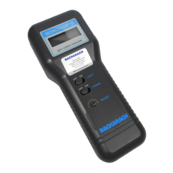
Single Gas Instrument Service Manual SERVICE MANUAL CONTENTS This manual contains the following service information for the . . . DIOXOR II (Part No. 0019-7038 & 0019-7043) MONOXOR II (Part No. 0019-7034 & 0019-7039) MONOXOR II H (Part No. 0019-8015) NONOXOR II (Part No. -
Page 5: Maintenance
(Chamber Assembly) and the Printed Circuit Board (P.C.B.) from the front case by pulling them straight up from the front case (Fig 2 -2); then lay these items on your workbench. Figure 2-1. Opening and Closing the Case Page 5 Instruction 0019-9166 Bacharach, Inc. -
Page 6: Closing The Case
5. Reinstall the batteries (observe proper battery polarity); replace the battery cover; and attach the elastic strap’s metal clip to the bottom of the instru- ment. Figure 2-2. P.C.B. and Chamber Assem- Removal and Installation Page 6 Bacharach, Inc. Instruction 0019-9166... -
Page 7: Cleaning
6. Clean the Chamber’s inlet and outlet ports using pipe cleaners dipped in warm, soapy water. After cleaning, dry them with clean dry pipe cleaners. 7. Reassemble the chamber assembly as follows: NOTE: DO NOT overtighten any screws; damage to plastic parts will result. Page 7 Instruction 0019-9166 Bacharach, Inc. - Page 8 Step 2 (Tighten to 4–8 oz. in.). 9. Close the case as per Section “2.2 Closing the Case.” Figure 2-3. Chamber As- sembly, Exploded View Figure 2-3A. Fan-blade assem- bly set screw Page 8 Bacharach, Inc. Instruction 0019-9166...
-
Page 9: Sensor Replacement
Nos.): • Phillips-head screwdriver, No. 1 • Replacement Sensor: • Nutdriver, 4mm (5/32") • Dioxor II - SO • Screwdriver, 1/8" fl at blade • Monoxor II - CO • O-Ring and Membrane, if required • Nonoxor II - NO •... -
Page 10: Printed Circuit Board Replacement
7. Close the case as per Section 2.2 Closing the Case.” 8. Calibrate the Sensor with the new P.C.B. as per Section “3.0 Sensor Calibra- tion.” 9. Discard the old P.C.B. Figure 2-4. Sensor & Motor Wiring Diagram Page 10 Bacharach, Inc. Instruction 0019-9166... -
Page 11: Chamber Assembly Servicing
6. Reassemble the chamber assembly with any replacement parts using Section 2.3, Step 7. 7. Reinstall the Membrane, O-ring, and Sensor using Section 2.3, Step 8. 8. Close the case as per Section “2.2 Closing the Case.” Page 11 Instruction 0019-9166 Bacharach, Inc. -
Page 12: Sensor Calibration
NOTE: An indication that the instrument was not zeroed in fresh air is when a large negative CO display appears when the instrument is moved into another area. b. Set front panel POWER switch to ON. Figure 3-1. Calibration Kit Setup Page 12 Bacharach, Inc. Instruction 0019-9166... -
Page 13: Dioxor Ii So2, Monoxor Ii H Co, And Nonoxor Ii Nox Calibration
CO gas in larger amounts, can be very toxic. Calibration at a Bacharach Sales/Service Center is recommended (See Section “5.4 Bacharach Sales/ Service Centers” to fi nd the nearest center). If you have a facility that is properly equipped to handle toxic gas (i.e.. -
Page 14: Troubleshooting Chart
Board Replacement.” LCD segments missing LCD loose or defective Carefully re-seat LCD in its socket. If segments are still missing, replace LCD. P.C.B. defective Replace P.C.B. Refer to Section “2.5 Printed Circuit Board Replacement.” Page 14 Bacharach, Inc. Instruction 0019-9166... - Page 15 Sensor connections loose or Check Sensor connections. broken See Fig 2-2. Sensor depleted or defective Replace Sensor. Refer to Section “2.4 Sensor Replace- ment.” P.C.B. defective Replace P.C.B. Refer to Section “2.5 Printed Circuit Board Replacement.” Page 15 Instruction 0019-9166 Bacharach, Inc.
- Page 16 Check operation of Motor. If Motor defective motor is receiving power but isn’t turning, replace Motor Assembly. Refer to Section “2.6 Chamber Assembly Servicing.” Replace P.C.B. Refer to Sec- P.C.B. defective tion “2.5 Printed Circuit Board Replacement.” Page 16 Bacharach, Inc. Instruction 0019-9166...
-
Page 17: Replacement Parts
0011-0074 Filter Packing 0011-0121 Filter Tube 0011-0130 Front Ferrule 0003-2024 Rear Ferrule 0003-2025 Knurled Nut 0003-2023 Compression Fitting 0003-2021 Barbed Fitting 0003-6164 Extended Adapter Block 0019-3072 Connector Tube 0011-0070 Figure 5-1. Standard Probe Assembly Page 17 Instruction 0019-9166 Bacharach, Inc. -
Page 18: Instrument Assembly
Adapter, Motor Shaft 0024-0412 Battery Clip, push on 0004-3113 Battery Cover with Foam Pad 0019-3029 Chamber 0019-3090 Front Cover w/Display Window (Dioxor II) 0019-3079 Front Cover w/Display Window (Monoxor II) 0019-3055 Front Cover w/Display Window (Nonoxor II) 0019-3078 Front Cover (Monoxor II H) (order with 0019-0437) - Page 19 Single Gas Instrument Service Manual Figure 5-3. Replacement Parts, Back and Front Exploded Views Page 19 Instruction 0019-9166 Bacharach, Inc.
-
Page 20: Miscellaneous Parts And Accessories
Carbon Monoxide Gas Cylinder, 500 ppm 0024-0492 Potentiometer adjustment tool 0006-9456 Custom Carrying Case (1 Instrument) 0019-0377 Custom Carrying Case (2 Instrument) 0019-3040 Instruction Manual, (Dioxor II) 0019-9121 Instruction Manual, (Monoxor II) 0019-9113 Instruction Manual, (Nonoxor II) 0019-9120 Instruction Manual, (Monoxor II H) 0019-9180...
Need help?
Do you have a question about the DIOXOR II and is the answer not in the manual?
Questions and answers