Table of Contents
Advertisement
Quick Links
Advertisement
Table of Contents

Related Manuals for Patton electronics 450RC24


Summary of Contents for Patton electronics 450RC24
- Page 1 USER MANUAL MODEL 450RC24 Ultra High Density G.703 Balun Panel (75-Ohm Coax to 120-Ohm 50-pin Telco) Part # 07M450RC24-A SALES OFFICE Doc. # 019151U (301) 975-1000 Released 6/25/01 TECHNICAL SUPPORT C E R T I F I E D (301) 975-1007 An ISO-9001 Certified...
-
Page 2: Table Of Contents
A.5 Data Rate ..................8 A.6 75-Ohm Connection ..............8 A.7 120-Ohm Connection ..............8 A.8 Power Supply .................8 A.9 Link-to-Data Isolation ..............8 A.10 Temperature Range ...............8 1.11 Dimensions (Without Handles) ............. 8 Model 450RC24 Factory Replacement Part....... 9 Model 450RC24 Block Diagram ..........10... -
Page 3: Warranty Information
Packages received without an RMA number will not be accepted. Patton Electronics' technical staff is also available to answer any ques- tions that might arise concerning the installation or use of your Model 450RC24. Technical Support hours: 8 AM to 5 PM EST, Monday through Friday. -
Page 4: General Information
2.0 GENERAL INFORMATION Thank you for your purchase of this Patton Electronics product. This product has been thoroughly inspected and tested and is warranted for One Year parts and labor. If any questions or problems arise during installation or use of this product, please do not hesitate to contact Pat- ton Electronics Technical Support at (301) 975-1007. -
Page 5: Description
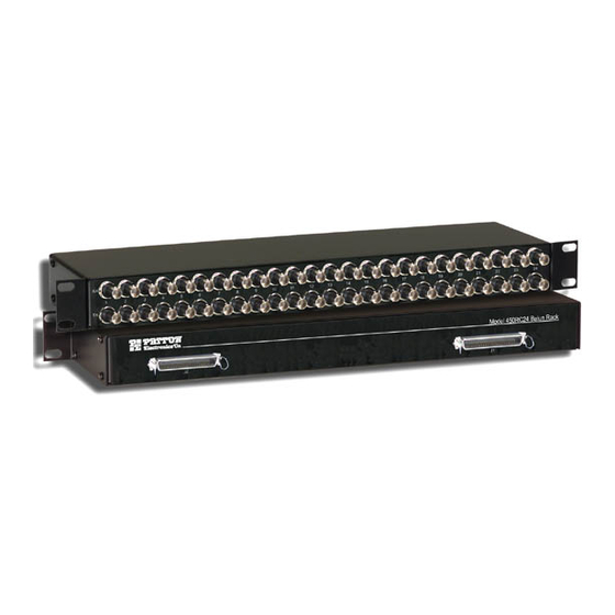
(in keeping with European ONP requirements). Figure 1. Model 450RC24 Supporting E1 data rates to 2.048 Mbps, the Patton 450RC24 panels bi- directionally match signal impedance and pulse shapes according to the CCITT G.703 standard. The Patton 450RC24 balun panels mount in a... -
Page 6: Installation
3.0 INSTALLATION This section describes how to connect to the twisted pair interface and the serial interface. This section also describes procedures to reverse the cover of the unit in order to mount the 50-pin Telco ports on the front of the unit. -
Page 7: Connecting The 75-Ohm Bnc Ports
The number of each coax pair corresponds to the two 50-pin Telco connector s pin numbers on the rear panel. Coax pairs 1—12 terminate on Telco connector J1; 13—24 terminate on J2. Figure 3. Model 450RC24 front panel The numbers on each coax pair correspond to the 50-pin Telco ports on the rear of the unit. -
Page 8: Model 450Rc24 Specifications
APPENDIX A MODEL 450RC24 SPECIFICATIONS A.4 TRANSMISSION LINE CCITT G.703 (unstructured) A.5 DATA RATE 2.048 Mbps A.6 75-OHM CONNECTION Dual coax female BNC A.7 120-OHM CONNECTION 50-pin Telco connector A.8 POWER SUPPLY None required A.9 LINK-TO-DATA ISOLATION 500 volts AC/DC A.10 TEMPERATURE RANGE... -
Page 9: Model 450Rc24 Factory Replacement Part
APPENDIX B MODEL 450RC24 FACTORY REPLACEMENT PART Model # Description 07M450RC24 Model 450RC24 User Manual 08450RC24 6-in. BNC Removal Tool... -
Page 10: Model 450Rc24 Block Diagram
APPENDIX C MODEL 450RC24 BLOCK DIAGRAM The pinouts on the 50-pin Telco connectors are as shown in Figure 5 and Figure 6 on page 11. TX1+ TX1- RX1+ RX1- TX2+ TX2- RX2+ RX2- TX3+ TX3- RX3+ RX3- TX4+ TX4- RX4+... - Page 11 TX13+ TX13- RX13+ RX13- TX14+ TX14- RX14+ RX14- TX15+ TX15- RX15+ RX15- TX16+ TX16- RX16+ RX16- TX17+ TX17- RX17+ RX17- TX18+ TX18- RX18+ RX18- TX19+ TX19- RX19+ RX19- TX20+ TX20- RX20+ RX20- TX21+ TX21- RX21+ RX21- TX22+ TX22- RX22+ RX22- TX23+ TX23- RX23+...
- Page 12 © Copyright 2001 Patton Electronics Company All Rights Reserved.