Panasonic TH-103PF10UK Operating Instructions Manual
High definition plasma display
Hide thumbs
Also See for TH-103PF10UK:
- Service manual (132 pages) ,
- Manual de instrucciones (56 pages) ,
- Operating instructions manual (60 pages)
Table of Contents
Advertisement
Quick Links
Advertisement
Table of Contents

Related Manuals for Panasonic TH-103PF10UK


Summary of Contents for Panasonic TH-103PF10UK
-
Page 1: Operating Instructions
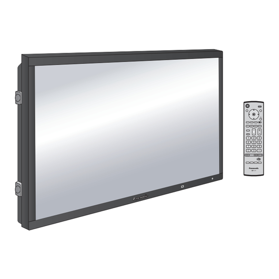
Operating Instructions High Defi nition Plasma Display TH-103PF10UK Model No. TH-103PF10UL The illustration shown is an image. Before connecting, operating or adjusting this product, please read these instructions completely. Please keep this manual for future reference. English TQBC2243-2... - Page 2 CAUTION RISK OF ELECTRIC SHOCK DO NOT OPEN WARNING: To reduce the risk of electric shock, do not remove cover or back. No user-serviceable parts inside. Refer servicing to qualifi ed service personnel. The lightning flash with The exclamation point within arrow-head within a triangle a t r i a n g l e i s i n t e n d e d t o is in tend ed to tell the user...
-
Page 3: Important Safety Instructions
Important Safety Instructions 1) Read these instructions. 2) Keep these instructions. 3) Heed all warnings. 4) Follow all instructions. 5) Do not use this apparatus near water. 6) Clean only with dry cloth. 7) Do not block any ventilation openings. Install in accordance with the manufacturer’s instructions. 8) Do not install near any heat sources such as radiators, heat registers, stoves, or other apparatus (including amplifi... -
Page 4: Table Of Contents
Dear Panasonic Customer Welcome to the Panasonic family of customers. We hope that you will have many years of enjoyment from your new Plasma Display. To obtain maximum benefit from your set, please read these Instructions before making any adjustments, and retain them for future reference. -
Page 5: Fcc Statement
To assure continued compliance, use only shielded interface cables when connecting to computer or peripheral devices. Any changes or modifications not expressly approved by Panasonic Corporation of North America could cause harmful interference and would void the user’s authority to operate this device. -
Page 6: Safety Precautions
This Plasma Display is for use only with the following optional accessories. Use with any other type of optional accessories may cause instability which could result in the possibility of injury. (All of the following accessories are manufactured by Panasonic Corporation.) • Pedestal ..............TY-ST103PF9 •... -
Page 7: Maintenance
• Doing so may cause the Plasma Display to overheat, electric shock. If the power cable is damaged, have it which can cause fire or damage to the Plasma repaired at your local Panasonic dealer. Display. If the Plasma Display will not be used for a long period Transport only in upright position! of time, unplug the power cord from the wall outlet. -
Page 8: Accessories
Accessories Accessories Supplied Check that you have the Accessories and items shown Operating Remote Control Batteries for the Fixing bands × 2 Instruction book Transmitter Remote Control EUR7636070R Transmitter (2 × AA Size) AC cord Allen wrench Eyebolt cap × 3 Remote Control Batteries Requires two AA batteries. -
Page 9: Connections
Connections AUDIO OUT Terminals connection Speakers (Optional accessories) AUDIO OUT Stereophonic sound code audio equipment AC cord connection (see page 13) AC cord connection (see page 13) line-in – AC cord fi xing Unplug the AC cord Close Close Push until the hook clicks. -
Page 10: Pc Input Terminals Connection
Connections PC Input Terminals connection COMPUTER AUDIO PC IN Conversion adapter (if necessary) Mini D-sub 15p PC cable Audio Stereo plug Connect a cable which matches the audio output terminal on the computer. Notes: • Due to space limitations, occasionally you may have trouble connecting Mini D-sub 15P cable with ferrite core to PC input Terminal. -
Page 11: Serial Terminals Connection
“ER401” command back to the computer. JUST JUST • SL1A, SL1B, SL2A and SL2B of Command IMS are SELF Panasonic AUTO available only when a dual input terminal board is With the power off, this display responds to PON command only. attached. -
Page 12: Hdmi Connection
Connections HDMI connection This unit has terminal boards equivalent to Dual HDMI Terminal Board (TY-FB10HMD) and BNC Component Video Terminal Board (TY-42TM6A) as standard equipment. [Pin assignments and signal names] Pin No. Signal Pin No. Signal T.M.D.S Clock T.M.D.S Data2+ Shield T.M.D.S Data2 T.M.D.S Clock-... -
Page 13: Power On / Off
Power ON / OFF Connecting the AC cord plug to the Plasma Display. Fix the AC cord plug securely to the Plasma Display with the clamper. (see page 9) Connecting the plug to the Wall Outlet. Note: When disconnecting the AC cord, be absolutely sure to disconnect the AC cord plug at the socket outlet fi... -
Page 14: Basic Controls
Basic Controls Main Unit Right side Enter / Aspect button surface (see page 16, 19) Volume Adjustment Volume Up “+” Down “–” ENTER/ When the menu screen is displayed: “+” : press to move the cursor up “–” : press to move the cursor down (see page 16) Remote control sensor MENU... -
Page 15: Remote Control Transmitter
Basic Controls Remote Control Transmitter Status button R button (see page 17) Press the “Status” button to display Press the R button to return to previous menu screen. the current system status. Input label Standby (ON / OFF) button Aspect mode (see page 19) The Plasma Display must fi... -
Page 16: On-Screen Menu Displays
On-Screen Menu Displays The MENU button on the unit can also be Press to select. To PICTURE adjust menu pressed. (see page 24) Right side PICTURE MENU surface NORMALIZE NORMAL INPUT PICTURE MENU STANDARD PICTURE Each time the MENU button is pressed, the [ from the unit ] BRIGHTNESS menu screen will switch. -
Page 17: To Setup Screensaver
AUTO VIDEO NR 3 : 2 PULLDOWN 3 : 2 PULLDOWN 3 : 2 PULLDOWN BLOCK NR VIDEO NR VIDEO NR Panasonic AUTO (4 : 3) NORMAL BLOCK NR MOSQUITO NR BLOCK NR VIDEO NR REFRESH RATE 100 Hz MOSQUITO NR... -
Page 18: Initial Selections
Initial selections Selecting the input signal Select the input signals to be connected by installing the optional Terminal Boards. Press to select the input signal to be played back from the equipment which has been connected to the Plasma Display. Input signals will change as follows: INPUT1 INPUT2A... -
Page 19: Aspect Controls
(see screen will return to a former adjustment. page 42). • Panasonic AUTO can not be selected while BNC Dual Video Terminal For a 4:3 image Board (TY-FB9BD) is installed. Note: Do not allow the picture to be displayed in NORMAL mode for an extended period, as this can cause a permanent... -
Page 20: Adjusting Pos. /Size
This picture position movement cannot be controlled by the V-POS POS. /SIZE function. V-SIZE • If adjusting the PICTURE V-POS / V-SIZE in Panasonic AUTO with FULL mode, the DOT CLOCK adjustment is not memorized. When exiting the mode, the screen will return to a CLOCK PHASE 1:1 PIXEL MODE former adjustment. - Page 21 Adjusting POS. /SIZE AUTO SETUP Automatically adjust H-POS / V-POS / CLOCK PHASE / DOT CLOCK and set H-SIZE / V-SIZE the standard value when RGB signal is input. Notes: • If the dot clock frequency is 162 MHz or higher, DOT CLOCK cannot be made. •...
-
Page 22: Multi Pip
MULTI PIP Press repeatedly. Each time pressing this button main picture and sub picture will be displayed as follows below. [Picture and Picture] [Picture out Picture] [Picture in Picture] Main picture Sub picture Main picture Sub picture Main picture Sub picture MULTI PIP MULTI PIP MULTI PIP... -
Page 23: Advanced Pip
Advanced PIP Press to display the Setup menu. Press to select “OSD Language”. Press and hold until the Options menu is displayed. Press to select Advanced PIP. Options Press to adjust the menu. Off : Sets normal two screen display mode Weekly Command Timer (see page 22). -
Page 24: Picture Adjustments
PICTURE Adjustments Press to display the PICTURE menu. Select to adjust each item. Press to select the menu to adjust. Select the desired level by looking at the picture behind the menu. Note: Menu that cannot be adjusted is grayout. Adjustable menu changes depending on signal, input and menu setting. -
Page 25: Advanced Settings
PICTURE Adjustments Notes: Item Effect Adjustments • “COLOR” and “TINT” settings cannot be adjusted for “RGB/PC” and “Digital” input PICTURE Adjusts the proper picture contrast. Less More signal. • You can change the level of each function Adjusts for easier viewing of dark (PICTURE, BRIGHTNESS, COLOR, TINT, BRIGHTNESS pictures such as night scenes and... -
Page 26: Sound Adjustment
SOUND Adjustment Press to display the SOUND menu. Select to adjust each item. Press to select the menu to adjust. Select the desired level by listening to the sound. BASS Adjusts low pitch sounds SOUND NORMALIZE NORMAL Adjusts normal sounds BASS TREBLE TREBLE... -
Page 27: Sdi Sound Output
SOUND Adjustment SDI SOUND OUTPUT This menu is displayed when HD-SDI Terminal Board with audio (TY-FB10HD) is installed to the unit. SDI SOUND OUTPUT CHANNEL 1 LEFT CHANNEL RIGHT CHANNEL CHANNEL 1 SOUND OUT LEVEL METER Item Details CHANNEL 1 to CHANNEL 16 LEFT Selects left audio channel. -
Page 28: Digital Zoom
Digital Zoom This displays an enlargement of the designated part of the displayed image. Display the operation guide. Press to access Digital Zoom. EXIT The operation guide will be displayed. During Digital Zoom, only the following buttons can be operated. [Remote control] [Unit] Right side surface... -
Page 29: Present Time Setup / Set Up Timer
PRESENT TIME SETUP / SET UP TIMER The timer can switch the Plasma Display ON or OFF. Before attempting Timer Set, confi rm the PRESENT TIME OF DAY and adjust if necessary. Then set POWER ON TIME / POWER OFF TIME. Press to display the SET UP menu. -
Page 30: Set Up Timer
PRESENT TIME SETUP / SET UP TIMER SET UP TIMER Display the SET UP TIMER SCREEN. Press to select SET UP TIMER POWER ON TIME / POWER OFF TIME. PRESENT TIME OF DAY 99:99 Press to set up POWER ON TIME / POWER OFF POWER ON FUNCTION TIME. -
Page 31: Screensaver
SCREENSAVER (For preventing image retention) Do not display a still picture, especially in NORMAL mode, for any length of time. If the display must remain on, a SCREENSAVER should be used. SET UP Press to display the SET UP menu. SCREENSAVER MULTI DISPLAY SETUP PORTRAIT SETUP... -
Page 32: Setup Of Screensaver Time
SCREENSAVER (For preventing image retention) Setup of SCREENSAVER Time After selecting TIME OF DAY or INTERVAL, the relevant Time Setup will become available for selection and the Operating Time may be set. (Time cannot be set when “MODE” is “ON” or “OFF”.) SCREENSAVER SCREENSAVER SCREENSAVER... -
Page 33: Side Bar Adjust
SCREENSAVER (For preventing image retention) SIDE BAR ADJUST side bars Do not display a picture in NORMAL mode for an extended period, as this can cause an image retention to remain on the side bars either side of the display fi eld. To reduce the risk of such an image retention, illuminate the NORMAL mode side bars. -
Page 34: Reduces Power Consumption
Reduces power consumption • POWER SAVE: When this function is turned ON, luminous level of the Plasma Display is suppressed, so power consumption is reduced. • STANDBY SAVE: When this function is turned ON, power consumption of the microcomputer is reduced during power supply standby (see page 13-15), so standby power of the set is reduced. -
Page 35: Set Up For Multi Display
SET UP for MULTI DISPLAY By lining up Plasma Displays in groups, for example, as illustrated below, an enlarged picture may be displayed across all screens. For this mode of operation, each plasma display has to be set up with a Display number to determine its location. (Example) group of 4 (2 ×... -
Page 36: How To Set The Display Location Number For Each Plasma Display
SET UP for MULTI DISPLAY How to set the Display location number for each Plasma Display Press to select HORIZONTAL SCALE. MULTI DISPLAY SETUP MULTI DISPLAY SETUP Press to select “× 1”, “× 2”, “× 3”, “× 4”, “× 5”. HORIZONTAL SCALE ×... -
Page 37: Id Remote Control Function
SET UP for MULTI DISPLAY AI-Control Adjusts brightness of displays when using MULTI DISPLAY. Press to select AI-Control. MULTI DISPLAY SETUP Press to select “OFF” , “ON”. MULTI DISPLAY SETUP HORIZONTAL SCALE × 2 Equalize the brightness of The brightness depends on VERTICAL SCALE ×... -
Page 38: Set Up For Portrait
SET UP for PORTRAIT Divide an input image into 3 parts, and display one of them to a plasma display which is set vertically. The image will be enlarged 3 times and rotated 90-degree. (Example) Note: When using the PORTRAIT function with displays set vertically, “V.Installation” in Options menu has to be set to “On” (see page 47). How to setup PORTRAIT Press to display the SET UP menu. - Page 39 SET UP for PORTRAIT VIEWING AREA / LOCATION VIEWING AREA: Set a mode of image division for PORTRAIT function. LOCATION: Set a location of image to be displayed for PORTRAIT function. PORTRAIT SETUP Press to select VIEWING AREA or LOCATION. PORTRAIT SETUP SEAM HIDES VIDEO Press to select each function.
-
Page 40: Set Up For Input Signals
Press ACTION ( ) button Press to exit from adjust mode. [ VIDEO ] SIGNAL 3D Y/C FILTER (NTSC) COLOR SYSTEM AUTO 3 : 2 PULLDOWN Panasonic AUTO (4 : 3) NORMAL Note: VIDEO NR When ON, this setting only affects NTSC input signals. -
Page 41: Video Nr / Block Nr / Mosquito Nr
3D Y/C FILTER (NTSC) SYNC AUTO AUTO COLOR SYSTEM 3 : 2 PULLDOWN 3 : 2 PULLDOWN VIDEO NR Panasonic AUTO (4 : 3) NORMAL BLOCK NR VIDEO NR MOSQUITO NR BLOCK NR REFRESH RATE 100 Hz Press to exit from adjust mode. -
Page 42: Color System / Panasonic Auto
SECAM M.NTSC NTSC Panasonic AUTO Set to “NORMAL” to view 4:3 images in an unchanged format when Panasonic AUTO is selected. (4 : 3 ) If you would like to view 4:3 images in Just format, set to “JUST”. Note: Panasonic AUTO does not function when BNC Dual Video Terminal Board (TY-FB9BD) is used. -
Page 43: Sync
SET UP for Input Signals SYNC Select SIGNAL from the “SET UP” menu during RGB input signal. SET UP Press to adjust. SIGNAL COMPONENT/RGB-IN SELECT INPUT LABEL POWER SAVE STANDBY SAVE POWER MANAGEMENT AUTO POWER OFF ENGLISH ( US ) OSD LANGUAGE Press ACTION ( ) button [ RGB ]... -
Page 44: Options Adjustments
Options Adjustments Press to display the Setup menu. Press to select “OSD Language”. Press and hold until the Options menu is displayed. Press to select your preferred menu. Press to adjust the menu. Options Weekly Command Timer Onscreen display O f f Initial INPUT Initial VOL level Maximum VOL level... - Page 45 Options Adjustments Options Weekly Command Timer Onscreen display Initial INPUT Initial VOL level Maximum VOL level INPUT lock Button lock Remocon User level Advanced PIP Item Effect Adjustments Press button to adjust the volume when the unit is turned on. Off: Sets normal volume.
- Page 46 Options Adjustments Options Off-timer function Enable Initial Power Mode Normal ID select Remote ID Serial ID Display size Studio W/B Studio Gain Item Effect Adjustments Enable: Enables the “Off-timer function”. Off-timer Disable: Disables the “Off-timer function”. function Enable Disable Note: When “Disable”...
- Page 47 Options Adjustments Options Slot power O f f Power On Screen Delay V. lnstallation Rotate Serial Slot Select Slot1 Item Effect Adjustments Auto Off: Power is not transmitted to the slot power. Auto: Power is transmitted to the slot power only when main power is on. Slot Power Power is transmitted to the slot power when main power is on or in the standby state.
-
Page 48: Weekly Command Timer
Options Adjustments Weekly Command Timer You can set 7-day timer programming by setting time and command. Note: Before setting Weekly Command Timer, set PRESENT TIME SETUP. (see page 29) Press to select Function. Options Press to select “On”. Weekly Command Timer Onscreen display Note: Press ACTION ( ) button... - Page 49 Options Adjustments Press to select a command number. Press to show the previous / next command pages (1-8) of the selected program. Press to show the command setting screen. Weekly Command Timer Weekly Command Timer Program Program AVL:00 8:00 20:00 DAM:NORM 10:30 IMS:SL1...
-
Page 50: Shipping Condition
Shipping condition This function allows you to reset the unit to the factory setting. Press to display the SET UP menu. Press to select “OSD LANGUAGE”. Press and hold till the SHIPPING menu is SET UP displayed. SIGNAL COMPONENT/RGB-IN SELECT INPUT LABEL POWER SAVE STANDBY SAVE... -
Page 51: Troubleshooting
Troubleshooting Before you call for service, determine the symptoms and make a few simple checks as shown below. Symptoms Checks Picture Sound Electrical Appliances Interference Noisy Sound Cars / Motorcycles Fluorescent light Volume Normal Picture No Sound (Check whether the mute function has been activated on the remote control.) Not plugged into AC outlet Not switched on No Picture... -
Page 52: Component/Rgb/Pc/Video Input Signals
COMPONENT/RGB/PC/VIDEO input signals Applicable input signals for Component / RGB, Mini D-sub 15P ( Mark) Component / RGB / Mini D-sub Signal name Horizontal frequency (kHz) Vertical frequency (Hz) 15P (Dot clock (MHz)) 525 (480) / 60i 15.73 59.94 * (13.5) ∗... - Page 53 COMPONENT/RGB/PC/VIDEO input signals VIDEO input (HDMI) Vertical Horizontal Dot clock Number of Total number Number of Total number Signal format frequency (Hz) frequency (kHz) (MHz) active pixels of pixels active lines of lines VGA60 59.94 31.47 25.18 525/60p 59.94 31.47 27.00 625/50p 50.00...
-
Page 54: Command List Of Weekly Command Timer
Audio Volume (60) DAM:FULL Aspect (FULL) DAM:JUST Aspect (JUST) DAM:NORM Aspect (NORMAL) DAM:SELF Aspect (Panasonic Auto) DAM:ZOOM Aspect (ZOOM) DWA:OFF Dual Picture mode (OFF) DWA:OVL1 Advanced PIP mode (1) (see page 23) DWA:OVL2 Advanced PIP mode (2) (see page 23) -
Page 55: Specifi Cations
Specifi cations TH-103PF10UK, TH-103PF10UL ∗ Power Source 200-240 V AC, 50/60 Hz (single phase) Power Consumption Power on 1,550 W Stand-by condition Save OFF 1.0 W, Save ON 0.9 W Power off condition 0.5 W Plasma Display panel Drive method : AC type 103-inch,... -
Page 56: Panasonic Plasma Screen Limited Warranty
TO DISCS) RESULTING FROM THE USE OF THIS may be obtained during the warranty period by contacting PRODUCT, OR ARISING OUT OF ANY BREACH OF Panasonic Professional Display Company Service toll free THE WARRANTY. ALL EXPRESS AND IMPLIED at 1-800-973-4390. -
Page 57: Limited Warranty Statement
Panasonic Canada Inc. 5770 Ambler Drive, Mississauga, Ontario L4W 2T3 LIMITED WARRANTY STATEMENT Panasonic Canada Inc. (also known as PCI) warrants this product to be free of WARRANTY COVERAGE PERIOD EXCEPTIONS defects in material and workmanship under normal use during the applicable... - Page 58 Memo...
- Page 59 Memo...
- Page 60 Executive Offi ce : One Panasonic Way 4E-7, Secaucus, NJ 07094 (201) 348-7000 EASTERN ZONE : One Panasonic Way 4E-7 Secaucus, NJ 07094 (201) 348-7621 Mid-Atlantic/New England : One Panasonic Way 4E-7 Secaucus, NJ 07094 (201) 348-7621 Southeast Region : 1225 Northbrook Parkway, Ste 1-160 Suwanee GA 30024 (770)338-6835 Central Region : 1707 N Randall Road E1-C-1, Elgin, IL 60123 (847)468-5200 WESTERN ZONE : 3330 Cahuenga Blvd W., Los Angeles, CA 90068 (323) 436-3500...
Need help?
Do you have a question about the TH-103PF10UK and is the answer not in the manual?
Questions and answers