Table of Contents
Advertisement
Quick Links
Advertisement
Table of Contents

Subscribe to Our Youtube Channel
Related Manuals for Packard Bell EasyNote MB Series


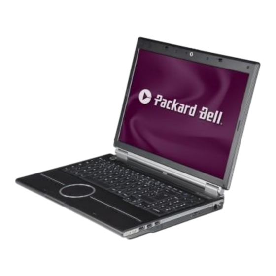
Summary of Contents for Packard Bell EasyNote MB Series
- Page 1 Packard Bell EasyNote MB Series Disassembly Guide...
-
Page 2: Table Of Contents
Table of Contents Overview ........................3 Technician Notes......................3 Disassembly Instructions..................3 Reassembly Instructions ..................3 Required Tools ......................3 Battery ........................4 Hard disk ........................4 Optical Drive......................6 Memory Modules ......................7 Wireless LAN card....................8 Intel Turbo Memory Module (optional)..............11 CPU........................11 Keyboard ........................13 LCD Assembly......................13 LCD Panel ......................15 Webcam .........................16 Inverterboard ......................17 Wireless Antenna ....................17... -
Page 3: Overview
This document contains step-by-step disassembly instructions for the EasyNote MB series. The instructions are illustrated where necessary with images of the part of the device that is being removed or disassembled. Packard Bell reserves the right to make changes to the EasyNote MB series without notice. Technician Notes Only technicians authorized by Packard Bell B.V. -
Page 4: Battery
Battery Push aside the 2 clips securing the battery. Fig. 1 Removing the battery. Pull out the battery Hard disk Remove the battery Remove the screw securing the hard disk cover. Fig. 2 The bottom of the notebook. Note: the screw does NOT stay attached to the cover. EasyNote MB Disassembly Manual... - Page 5 Remove the 2 screws of the HDD bracket and take away the bracket. Fig. 4 The HDD and its bracket. Note: The EasyNote MB series use S-ATA hard disks. S-ATA hard disks have no master/slave settings (so no jumpers needed).
-
Page 6: Optical Drive
Optical Drive Remove the battery Remove the 2 screws securing the optical drive. Fig. 5 The optical drive screws. Use the emergency-eject to open the drive tray. Pull the drive out. Close the tray again. Fig. 6 Removing the optical drive. EasyNote MB Disassembly Manual... -
Page 7: Memory Modules
Remove the 2 brackets from the optical drive (1x 2 and 1x 1 screws). Fig. 7 The optical drive brackets. Remove the bezel: push the 2 clips to push the bezel loose Fig. 8 Removing the optical drive bezel. Memory Modules Remove the battery. -
Page 8: Wireless Lan Card
Note: the screws stay attached to the cover. Lift the door out. The memory module(s) are located in the bottom middle of the compartment. To release the modules, push the metal clips aside. This will release the module. Fig. 10 Removing the memory modules. Note: it may be necessary to push the WLAN antenna aside to have enough clearance for the left-side clip of the bottom SO-DIMM slot. - Page 9 Fig. 11 The bottom base screws. Note: the screws stay attached to the cover. Lift the door out. The Wireless LAN adapter is located to the left side. Remove the two screws securing the card and lift the card up. Fig.
- Page 10 Now disconnect the WLAN antenna. Note the colour of each wire that is attached to each connector, to ensure proper reconnection during re- assembly. Remove the card from its slot. Note: dependent on the model there may be 2 or 3 antennas. Some cards use ‘ main’ and ‘...
-
Page 11: Intel Turbo Memory Module (Optional)
Intel Turbo Memory Module (optional) An Intel Turbo Memory module can be used instead of a TV-card. Disassembly instructions are therefore identical, except that there is no antenna on a Turbo Memory Module. Remove the battery. Remove the 4 screws of the cover on the bottom base (see Fig. - Page 12 Fig. 14 The heatsink. Lift out the heatsink. Fig. 15 The CPU. Turn the screw in the CPU socket 180 degrees. Lift the CPU out. Note: The socket used on the EasyNote MB65, MB66, MB85 and MB86 resembles the CPU socket used for older Celeron M, Pentium M, Core Duo and Core 2 Duo systems a lot.
-
Page 13: Keyboard
Keyboard Remove the battery Push back the 4 clips securing the keyboard. Fig. 16 The keyboard clips. Lift up the keyboard. Disconnect the flatcable Fig. 17 The keyboard flatcable. Lift out the keyboard. LCD Assembly Remove the battery. Disconnect the WLAN antenna as described above. Remove screw ‘... - Page 14 Fig. 18 The LCD cable. Remove two screws located near the edges on the rear side bottom of the unit. Remove the two screws from the rear side of the unit. Fig. 19 The bottom of the notebook. Remove the 2 hinge covers. You can leverage them loose with a small flathead screwdriver.
-
Page 15: Lcd Panel
LCD Panel Remove the LCD Assembly as described above Remove the 6 rubber stoppers in the LCD bezel. Note: the 2 rubber stoppers used on the upper corners are different from the other 4 rubbers. Remove the screws in the bezel. Fig. -
Page 16: Webcam
Fig. 21 The LCD brackets and the inverterboard. Webcam Remove the LCD Assembly as described above Remove LCD bezel as described above. Disconnect the cable from the webcam. Fig. 22 The webcam. Remove the 2 screws from the webcam module. Lift out the webcam module. -
Page 17: Inverterboard
Inverterboard Remove the LCD Assembly as described above Remove LCD bezel as described above. Disconnect the 2 cables from the inverterboard. Remove the screw from the inverterboard. Remove the inverterboard; it is glued in place. Wireless Antenna Remove the LCD Assembly and Panel as described above Remove the 2 screws of both the wireless antenna clips. -
Page 18: Top Cover
Top Cover Remove the battery, hard disk, optical drive, memory modules, Wireless LAN, TV-Card or Intel Turbo Memory, CPU, keyboard and LCD Assembly as described above. Remove the remaining screws in the bottom base (8 long screws, 2 shorter screws in the hard disk bay and 2 in the optical drive bay). Fig. -
Page 19: Mainboard
Remove the top cover. Mainboard Remove the top cover, as described above. Remove the 2 hex-bolts adjacent to the DVI-I Connector. Disconnect all cables from the mainboard. Fig. 27 The bottom base assembly. Remove the 6 screws marked with a screw-sign on the mainboard. Fig. -
Page 20: Bluetooth Module
Bluetooth Module Remove the top cover as described above. Disconnect the Bluetooth cable from the Bluetooth module. Fig. 29 The Bluetooth cable. Take out the Bluetooth module; it is glued in place. USB and Audio board Remove the top cover as described above. Disconnect the flatcable from the USB/Audio board. -
Page 21: Dc Jack
DC Jack Remove the top cover as described above. Disconnect the DC jack connector from the mainboard. Fig. 31 The DC jack connector. Remove the metal shield covering the DC Jack and modem connector. Fig. 32 The small metal shield. Lift the DC Jack from its bracket. -
Page 22: Modem Connector
Modem Connector Remove the mainboard as described as above. Remove the metal shield covering the DC Jack and modem connector. Lift the modem connector from its bracket. Remove the modem cable from the clips securing it in place. Speakers and Subwoofer The speakers and subwoofer are shipped as part of the bottom base and do not require further disassembly. -
Page 23: Reassembly Notes
Packard Bell B.V. PACKARD BELL B.V. SHALL NOT BE LIABLE FOR TECHNICAL OR EDITORIAL ERRORS OR OMISSIONS CONTAINED HEREIN; NOR FOR INCIDENTAL OR CONSEQUENTIAL DAMAGES RESULTING FROM THE FURNISHING, PERFORMANCE, OR USE OF THIS MATERIAL.
Need help?
Do you have a question about the EasyNote MB Series and is the answer not in the manual?
Questions and answers