Table of Contents

Related Manuals for DSC MAXSYS PC4010


Summary of Contents for DSC MAXSYS PC4010
- Page 1 PC4010 v3.0 • Instruction Manual WARNING: This manual contains information on limitations regarding product use and function and information on the limitations as to liability of the manufacturer. The entire manual should be carefully read.
-
Page 2: Fcc Compliance Statement
FCC COMPLIANCE STATEMENT CAUTION: Changes or modifications not expressly approved by Digital Security Controls Ltd. could void your authority to use this equipment. This equipment has been tested and found to comply with the limits for a Class B digital device, pursuant to Part 15 of the FCC Rules. -
Page 3: Table Of Contents
Table of Contents Introduction Section 1: General System Operation Getting to Know Your System ............3 How to Arm ..................4 Alternate Arming Methods ............5 Disarming ..................6 Alarm Memory ................. 6 If An Alarm Sounds ................. 7 Zone Bypassing ................7 Trouble Conditions ................ -
Page 4: Introduction
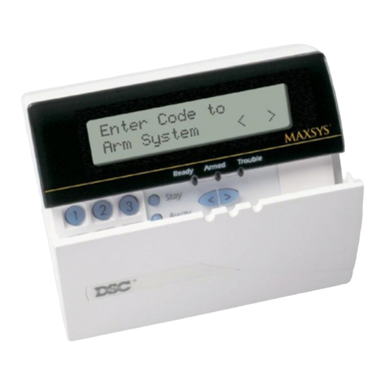
Introduction About Your Security System Your DSC security equipment has been designed to give you the greatest possible flexibility and convenience. The LCD keypad will guide you through each operation with English language prompts. The keypad provides audible feedback each time a key is pressed; with unique audible sequences, it will also signal system troubles and other indications of system status. -
Page 5: Section 1: General System Operation
Section 1: General System Operation 1.1 Getting to Know Your System Your security system is made up of a control panel, one or more keypads and various detectors and sensors. The control panel will be mounted out of the way in a utility room or basement. The metal control cabinet contains the system’s electronics and stand-by battery. -
Page 6: How To Arm
If required, the system may have a global keypad. A global keypad can access any partition. When you enter your access code at a global keypad, you will be asked which partition you would like to arm. The keypad will only offer the partitions available for your access code. -
Page 7: Alternate Arming Methods
S e c t i o n G e n e r a l S y s t e m O p e r a t i o n If you wish to arm another partition, use the arrow (< >) keys to scroll though the partitions available to be armed by your access code. -
Page 8: Disarming
Quick Arm When the Quick Arm feature is enabled, the system may be armed by simply pressing [*][0] instead of your access code. Please note that pressing [*][0] will only allow you to arm the system; to disarm, you must enter a valid access code. -
Page 9: If An Alarm Sounds
S e c t i o n G e n e r a l S y s t e m O p e r a t i o n 1.6 If An Alarm Sounds Fire Alarm If your system has been installed with fire detectors, a fire alarm will be indicated by a pulsing siren. -
Page 10: Trouble Conditions
[1] Bypass Zones – This selection takes you immediately to bypassing zones. Use the arrow (< >) keys to find the zone to be bypassed and press the [*] key to select it. A “*” will appear next to the zone label to indicate that the zone has been bypassed. -
Page 11: Section 2: Access Codes
Section 2: Access Codes Access codes are used to arm and disarm the system as well as to access system functions. There are many different codes available on the system. The Grand System Master Code will be able to perform all system functions. - Page 12 Program Code To program the code for the new access code, perform the following: 1. From the Program Code menu, use the arrow keys to scroll to the first message: “Select (0) Program Code.” Press [0] or [*] to program the access code.
-
Page 13: Modify An Existing Code
S e c t i o n A c c e s s C o d e s To program partition access for the new access code, perform the following: 1. From the Program Code menu, use the right arrow (>) key to scroll to the following display: Select (6) <... -
Page 14: Change User Code Options
Once the code has been selected, the Program Code menu will be shown. Reprogram the access code, code label or partition access using the steps outlined in Section 2.1 “Program a New Code”. 2.3 Change User Code Options User code options determine which system features the code will be able to access. - Page 15 S e c t i o n A c c e s s C o d e s...
-
Page 16: Delete An Existing Code
2.5 Delete an Existing Code An access code may be erased in two parts. First, all data pertaining to the code may be deleted (access code, user options, partition access, etc.). The access code label is erased separately. To delete all access code data from an existing code, perform the following: 1. -
Page 17: Installer Programmed Codes
S e c t i o n A c c e s s C o d e s Duress Codes If the “Duress” user option is enabled, the code will become a Duress code. When this code is entered, the system will send a duress signal to the monitoring station. -
Page 18: Section 3: System Administration
Section 3: System Administration 3.1 Quick Arm Keypad Command: [*][6][Access Code] This option will allow the system to be armed by entering [*] [0] at any keypad instead of entering an access code. This option must be enabled in order for the Stay or Away function keys to work. To turn this feature on, perform the following: 1. - Page 19 S e c t i o n S y s t e m A d m i n i s t r a t i o n 2. Use the arrow keys (< >) to scroll to the message “Auto Arm Control.” Press [*].
-
Page 20: Setting The Time And Date
3.4 Setting the Time and Date Keypad Command: [Master Code][9] To set the time and date on the system, perform the following: 1. Enter a Master code and press [9]. The display will read “System Master Menu.” 2. Use the keypad arrow keys (< >) to scroll to the display “Set System Time.”... -
Page 21: Command Outputs 1-8
S e c t i o n S y s t e m A d m i n i s t r a t i o n 3.7 [*][7] Command Outputs 1-8 Keypad Command: [*][7][1-8] These outputs must be programmed by your installer. Up to eight command outputs can be added to your system. - Page 22 User Call Up When this option is activated, the alarm control panel will call the downloading computer. The downloading computer must be waiting for the call in order for downloading to begin. To start user call up, perform the following: 1.
-
Page 23: Section 4: Access Control
Section 4: Access Control NOTE: This section only applies to systems that have the PC4820 Access Control module installed. Talk to your installer for information regarding the access control capabilities of your system. 4.1 Access Card Readers To gain access to an area via a door with an access card reader, present your access card through the reader. -
Page 24: Access Card Programming
4.2 Access Card Programming Access card programming is a part of access code programming. An access card is assigned to a single user of the system. A user can have both an access code and an access card to provide two different means of accessing the system. - Page 25 S e c t i o n A c c e s s C o n t r o l Your installer will customize access levels 02-63 to suit your purposes. Assigning access level 00 means that the user will never have access to a given area.
-
Page 26: Search Using Access Card Numbers
4.3 Search Using Access Card Numbers In Section 2.2 “Modify an Existing Code,” two methods were outlined for searching for existing users: by access code number and by user name. You may also search by access card number. To do so, perform the following: 1. -
Page 27: Section 5: Testing And Maintenance
Section 5: Testing and Maintenance IMPORTANT NOTE: Test your system on a weekly basis and have any system trouble conditions corrected by your installer or service technician. 5.1 Walk Test Keypad Command: [*][6][Walk Test Code] The Walk Test feature allows you to test if the detectors on a partition are in proper working order. -
Page 28: System Test
Disable Walk Test To end every walk tests—except the “AML Smoke Test”—this option must be selected. Once you have completed your test, enter [*] [6] [Walk Test Code]. Use the arrow keys to scroll to this option and press [*]. The partition will return to its normal disarmed state. -
Page 29: Section 6: Fire Safety
Section 6: Fire Safety 6.1 Fire Alarm Operation The following explains the fire alarm function of this system. 1. Fire Bells Sound Upon a fire alarm, the bells or sirens will sound. They will pulse on and off in a programmed pattern. The keypad will display the following: First Fire Alarm [Zone Label] The display will indicate the first fire zone in alarm, followed by any... - Page 30 Additional smoke detectors beyond those required should be installed for increased protection. The added areas include: basement, bedrooms, dining rooms, furnace room, utility room and hallways not protected by the required detectors. Family Room Bedroom Bedroom Bedroom Dining Bedroom Room Living Room Kitchen...
-
Page 31: Household Fire Safety Audit
S e c t i o n F i r e S a f e t y 6.3 Household Fire Safety Audit Most fires occur in the home. To minimize this danger, a household fire safety audit should be conducted and a fire escape plan should be developed and practised. - Page 32 • A good plan emphasizes quick escape. Do not investigate or attempt to fight the fire, and do not gather belongings or pets as this wastes valuable time. Once outside, do not re-enter the house. Wait for the fire department. •...
-
Page 33: Appendix A - Special Characters
Appendix A – Special Characters Below is a chart indicating the available ASCII characters and the 3-digit number required for each character. Instructions on programming ASCII characters is outlined in Section 2 “Access Codes.”... -
Page 34: Limited Warranty
LIMITED WARRANTY Digital Security Controls Ltd. warrants the origi- Digital Security Controls Ltd.’s liability for fail- ure to repair the product under this warranty after nal purchaser that for a period of twelve months a reasonable number of attempts will be limited from the date of purchase, the product shall be free of defects in materials and workmanship under to a replacement of the product, as the exclusive... -
Page 35: Warning Please Read Carefully
which follow. The smoke detectors may have been improp- WARNING Please Read Carefully erly installed or positioned. Smoke may not be able to reach the smoke detectors, such as when the fire is in a chimney, Note to Installers walls or roofs, or on the other side of closed doors. Smoke This warning contains vital information. - Page 36 Security Products ©1998 Digital Security Controls Ltd. Printed in Canada 29003126 R0 AVIS: L’étiquette de l’Industrie Canada identifie le NOTICE: The Industry Canada label identifies matériel homologué. Cette étiquette certifie que le certified equipment. This certification means that the matériel est conforme à certaines normes de protection, equipment meets certain telecommunications network d’exploitation et de sécurité...
Need help?
Do you have a question about the MAXSYS PC4010 and is the answer not in the manual?
Questions and answers