Table of Contents
Advertisement
Quick Links
Advertisement
Table of Contents

Subscribe to Our Youtube Channel
Related Manuals for Supermicro SuperBlade


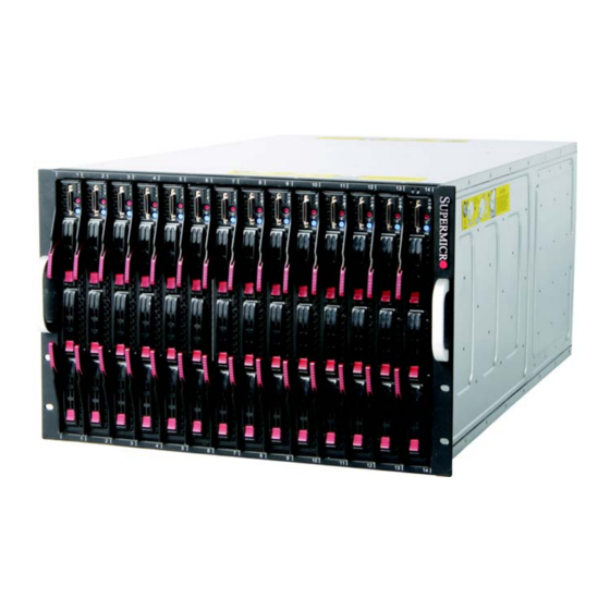
Summary of Contents for Supermicro SuperBlade
- Page 1 ® SuperBlade User’s Manual Revison 1.1...
- Page 2 This product, including software and documentation, is the property of Supermicro and/or its licensors, and is supplied only under a license. Any use or reproduction of this product is not allowed, except as expressly permitted by the terms of said license.
-
Page 3: About This Manual
SuperBlade. Chapter 3: Setup and Installation Refer here for details on installing the SuperBlade system into a rack. Chapter 4: System Modules This chapter covers modules in the SuperBladeSuperBlade system. It also covers the CMM module and configuring double-wide bays. - Page 4 SuperBlade User’s Manual Notes...
-
Page 5: Table Of Contents
Operating System Support..............1-10 Remote Management ................1-10 Computing Density/Power ..............1-10 High-Efficiency Power Supplies ............1-11 1-8 Returning Merchandise for Service ..........1-11 1-9 Contacting Supermicro ..............1-12 Chapter 2 System Safety ..............2-1 2-1 Electrical Safety Precautions ............2-1 2-2 General Safety Precautions ............. - Page 6 SuperBlade User’s Manual Choosing a Setup Location..............3-1 Rack Precautions..................3-2 Server Precautions ................. 3-2 Rack Mounting Considerations ............... 3-2 Ambient Operating Temperature ............3-2 Reduced Airflow ................... 3-2 Mechanical Loading ................3-3 Circuit Overloading................3-3 Reliable Ground ................... 3-3 Installing the System Into a Rack............
- Page 7 Chapter 5 Power Supply Modules ..........5-1 5-1 Power Supply Modules ..............5-1 Power Supply Failure................5-6 Installing a Power Supply................ 5-6 Removing a Power Supply..............5-6 5-2 Power Supply Fans ................5-7 5-3 Power Components ................5-8 Power Cord ..................... 5-8 Power Cord Tie and Clamp..............
- Page 8 SuperBlade User’s Manual Notes viii...
- Page 9 List of Figures Figure 3-1. Positioning the Enclosure Template ..........3-4 Figure 3-2. Securing the Rails to the Rack ............3-4 Figure 3-3. Attaching the Optional Handles ............3-5 Figure 3-4. Enclosure Installed into Rack ............3-6 Figure 4-1. Typical Blade System Module Configuration: Rear View ....4-1 Figure 4-2.
- Page 10 SuperBlade User’s Manual Notes...
- Page 11 List of Tables Table 1-1. SuperBlade Enclosures ..............1-5 Table 1-2. Number of Network Modules that May Be Installed in each Enclosure....................1-7 Table 4-1. Typical Blade System Module Configuration: Rear View....4-1 Table 4-2. CMM Module Interface..............4-3 Table 4-3. CMM Module Features ..............4-3 Table 4-4.
- Page 12 SuperBlade User’s Manual Notes...
-
Page 13: Chapter 1 Introduction
SuperBlade (www.supermicro.com/products/superblade/). Quick Start Setup This section covers how to quickly get your new SuperBlade system up and running. Follow the procedure below to quickly setup your SuperBlade system. 1. Unpack the components of your SuperBlade system and check the packing list for damaged or missing components. -
Page 14: Officeblade And Datacenterblade Systems
CD-ROM for details. 8. Connect the power cords for your SuperBlade system’s power supply and plug them into your power source ONLY after you have installed and secured all system components. -
Page 15: Officeblade
5200 series CPUs with 1333 FSB support be used in each blade module. Twin Blades Some blade modules for the SuperBlade system contain two (twin) nodes that allow the blade module to function as effectively two server systems. This allows an enclosure with these “twin”... -
Page 16: Product Checklist Of Typical Components
Blade Enclosure (x1): SBE-710E/Q, SBE-720E, SBE-720D-R75 or SBE-720D-D50 (10-blade series); SBE-714D/E (14-blade series) • Blade Unit (minimum of 2, 10 or 14 maximum): See the the Supermicro website (http://www.supermicro.com/products/superblade/) for a complete list of blades that can be mounted in your system. -
Page 17: Blade Enclosure Features
Chapter 1: Introduction Blade Enclosure Features Supermicro's blade enclosures are designed to house from 10 to 14 blade units. Each accommodates either two or more power supplies. The enclosure mid-plane allows the blade units to share certain functions such as power, cooling and networking. - Page 18 SuperBlade User’s Manual Table 1-1. SuperBlade Enclosures (Continued) Power Enclosure Blade Module Intel Blade AMD Blade Module Supply Model Capacity Options Options Options Options SBM-CMM-001 or BMB-CMM-002 SBI-7426T-S3 (Mini-CMM) SBI-7426T-T3 SBM-GEM-001, SBM-GEM-002 or SBI-7426T-SH 1400W SBE-714E 14-blade Modules SBM-GEM-X2C+ 1620W...
-
Page 19: Table 1-2. Number Of Network Modules That May Be Installed In Each Enclosure
Chapter 1: Introduction NOTE 3: When the SBM-GEP-T20 is installed, one SBM-GEM-X2C+ and one InfiniBand QDR switch or 10-Gb switch can also be supported. NOTE: The SBE-720E and SBE-720D series enclosures support only one CMM module. When equipped with redundant QDR IB switches or 10 Gb Ethernet switches, one of the switches must have a BMB-CMM-002 Mini-CMM installed. -
Page 20: Power
SuperBlade User’s Manual The following sections provide a general outline of the main features for all blade server enclosures. Power The typical blade enclosure features a 2500W, 2000W, 1620W or 1400W power system composed of two active power supply modules. An alternate configuration (and required for a full 10 or 14-blade system) features a total of four power supply modules for redundancy. -
Page 21: Power Supply Features
Power Supply Features The SuperBlade enclosure comes standard with one CMM module and either two or four power supplies. Information on the power supplies is summarized below. See Section 4-1: Chassis Management Module on page 4-2... -
Page 22: Power Supply Failure
Dual and quad core processors are supported in the blade module systems. Each SuperBlade mainboard supports two or four processors and up to 256 GB of main memory. This translates to a maximum potential of up to 40 processors and 2560 GB of memory per 7U enclosure or 240 processors and 15 TB of memory for a full 42U rack. -
Page 23: High-Efficiency Power Supplies
A reliable source of power is critical in server systems and even more so in a blade system, where up to fourteen systems (blades) share the same power source. SuperBlade power supplies have been designed to operate at up to 94% peak efficiency and provide redundancy. Using high-efficiency power supplies results in a measurable reduction in wasted energy consumption and generated heat. -
Page 24: Contacting Supermicro
SuperBlade User’s Manual Contacting Supermicro Headquarters Address: Super Micro Computer, Inc. 980 Rock Ave. San Jose, CA 95131 U.S.A. Tel: +1 (408) 503-8000 Fax: +1 (408) 503-8008 marketing@supermicro.com (General Information) Email: support@supermicro.com (Technical Support) Web Site: www.supermicro.com Europe Address: Super Micro Computer B.V. -
Page 25: Chapter 2 System Safety
System Safety Electrical Safety Precautions Basic electrical safety precautions should be followed to protect yourself from harm and the SuperBlade from damage: • Be aware of how to power on/off the enclosure power supplies and the individual blades as well as the room's emergency power-off switch, disconnection switch or electrical outlet. -
Page 26: General Safety Precautions
General Safety Precautions Follow these rules to ensure general safety: • Keep the area around the SuperBlade clean and free of clutter. • Place the blade module cover and any system components that have been removed away from the system or on a table so that they won't accidentally be stepped on. -
Page 27: Operating Precautions
Chapter 2: System Safety Operating Precautions Care must be taken to assure that the cover of the blade unit is in place when the blade is operating to assure proper cooling. Out of warranty damage to the blade can occur if this practice is not strictly followed. - Page 28 SuperBlade User’s Manual Notes...
-
Page 29: Chapter 3 Setup And Installation
If the server itself shows damage you should file a damage claim with the carrier who delivered it. Decide on a suitable location for the rack unit that will hold the SuperBlade. It should be situated in a clean, dust-free area that is well ventilated. Avoid areas where heat, electrical noise and electromagnetic fields are generated. -
Page 30: Rack Precautions
SuperBlade User’s Manual WARNING: Please read the following important Warnings and Precautions! Rack Precautions The following are important precautions concerning rack setup: • The enclosure unit is heavy and requires at least two people to lift it. • Ensure that the leveling jacks on the bottom of the rack are fully extended to the floor with the full weight of the rack resting on them. -
Page 31: Mechanical Loading
Powering and Grounding Electronic Equipment Installing the System Into a Rack This section provides information on installing the SuperBlade into a rack. There are a variety of rack units on the market, meaning the procedure may differ slightly. Refer to the Enclosure Template that was included with the system for help. -
Page 32: Installation
SuperBlade User’s Manual Installation Use the procedure below for installing an enclosure in a rack. Installing an enclosure: 1. Decide where you want to place the blade enclosure into the rack (see "Rack Mounting Considerations" in the previous section). 2. Position the Enclosure Template at the front of the enclosure to determine the... -
Page 33: Figure 3-3. Attaching The Optional Handles
Chapter 3: Setup and Installation NOTE: These handles are optional and need only be installed when mounting the system into a short rack. When mounting into a deep rack, they are unnecessary and regular screws should be used instead of thumbscrews. Be aware that these handles are not to be used for lifting the system, they are only to be used to slide the system within the rack. -
Page 34: Figure 3-4. Enclosure Installed Into Rack
SuperBlade User’s Manual Figure 3-4. Enclosure Installed into Rack... -
Page 35: Chapter 4 System Modules
Chapter 4 System Modules In addition to the blade units, your blade system comes equipped with one or more system modules. The modules fit into the rear of the enclosure into bays above and/or below the power supplies. This chapter describes the various blade modules that may be part of your blade system. -
Page 36: Chassis Management Module
Empty bay with dummy cover Power Supply (x2 required, x4 optional depending upon system requirements) NOTE: See the SuperBlade Network Modules User’s Manual on your enclosed CD-ROM disc for details on all 1Gb Ethernet modules, 1Gb pass-through modules, 1/10Gb Ethernet modules, 10Gb Ethernet pass-through modules, 10 Gb Ethernet Switch module and InfiniBand modules for the SuperBlade system. -
Page 37: Figure 4-2. Chassis Management Module
Chapter 4: System Modules Figure 4-2. Chassis Management Module Table 4-2. CMM Module Interface Item# Description Power LED Heartbeat LED Fault LED Ethernet Port VGA (Monitor) Port USB Ports Reset Button Module Release Handle USB 2.0/1.1 Switch (accessed at back of module, see Figure 4-8) Table 4-3. -
Page 38: Module Redundancy
NOTE: The Slave CMM keeps the same log/status as the Master CMM. SBM-CMM-001 or SBM-CMM-003 Module Installation Use this procedure to install the SBM-CMM-001 or SBM-CMM-003 CMM modules to the SuperBlade chassis. Make sure the cover to the module has been installed before proceeding. Follow the anti-static precautions described in Chapter Installing the Module: 1. -
Page 39: Bmb-Cmm-002 Module Installation
Chapter 4: System Modules BMB-CMM-002 Module Installation Use this procedure to install the BMB-CMM-002 Mini-CMM to the 10 Gb Ethernet Pass-through Module, the 10 Gb Ethernet Switch or an InfiniBand QDR switch. Follow the anti-static precautions described in Chapter Installing the Add-on Card 1. -
Page 40: Figure 4-4. Mini-Cmm Mounted On Module Board
SuperBlade User’s Manual 3. Fasten the screws to secure the Mini-CMM (Figure 4-4). Figure 4-4. Mini-CMM Mounted on Module Board Screws 4. Replace and resecure the switch/module’s cover. Removing the Add-on Card 1. Remove the switch/module’s top cover. 2. Unscrew the Mini-CMM from its mountings in the switch/module and remove it. -
Page 41: Configuring The Cmm
Chapter 4: System Modules Configuring the CMM To access/configure the CMM, you first have to configure the IP settings of the CMM depending on you network environment. The below procedure for this configuration just serves as a reference for getting the CMM setup. If your system has Linux OS, please follow similar instructions to get the CMM setup. -
Page 42: Figure 4-6. Manually Configure The Ip Address
SuperBlade User’s Manual 4. Manually configure the IP address of the computer system to be in the same address range as the CMM (see Figure 4-6). Example: • IP address: 192.168.100.101 • Subnet Mask: 255.255.255.0 • Default Gateway: 192.168.100.1 Figure 4-6. Manually Configure the IP Address 5. -
Page 43: Cmm Functions
SuperBlade enclosures/CMM’s to manage all of them in a similar way. In addition to accessing the SuperBlade capabilities through CMM, they can also be accessed directly on a blade by blade basis if the blades are equipped with SIMBL to... -
Page 44: Local Kvm
SuperBlade User’s Manual Local KVM KVM stands for Keyboard/Video/Mouse. With KVM, a user can control multiple blades with a single keyboard/video/mouse setup. The maximum video resolution the KVM can support is 1280 x 1024 @ 60 Hz. To Use: Connect your keyboard, mouse and monitor to the USB and VGA connectors on the CMM module, then push the KVM button on the control panel of the blade module you wish to access. -
Page 45: Power Consumption Management
Chapter 4: System Modules Power Consumption Management The CMM module’s firmware can also control all power on/off activity in the whole blade system. This is done by using the Power button, via a SIMBL add-on card, onboard BMC or from any other use of remote management software. Once a blade module is installed in the enclosure the installed CMM immediately receives information on the rated Max Power Consumption value of the new blade module. -
Page 46: Reset Button
The Web-based Management Utility is a web-based interface that consolidates and simplifies system management for Supermicro SuperBlade systems. The Web-based Management Utility aggregates and displays data from the CMM module. -
Page 47: Supported Browsers
2. In the address field of the browser, enter the IP address that you assigned to the Chassis Management Module and hit the <E > key. NTER 3. When the browser makes contact with Supermicro’s Chassis Management Module, enter your username and password, then click L OGIN 4. The W... -
Page 48: Home Page
SuperBlade User’s Manual Home Page Figure 4-9 Table 4-6 respectively display the W BASED ANAGEMENT TILITY and its controls. Figure 4-9. Home Page Table 4-6. Home Page Controls Item Description Home: Click this icon to return to the Home Page. -
Page 49: Double-Wide And Triple-Wide Modules
Chapter 4: System Modules Double-Wide and Triple-Wide Modules Most modules in the SuperBlade fit into single-wide bays. The InfiniBand module and some other modules however (such as the 10GbE Pass-through module and 10 Gb Switch Module), require a double-wide bay. Some need a triple-wide bay (such as the SBM-IBP-D14 InfniBand Pass-through Module) that are created by combining three bays. -
Page 50: Figure 4-10. Horizontal Spacers For Single Bays
SuperBlade User’s Manual NOTE: Unless it is capable of supporting the mini-CMM, only one double-wide module can be installed in an enclosure since each enclosure requires at least one CMM module. The bottom location is recommended. If using the AOC-IBH-002, AOC-IBH-XQS or AOC-IBH-XDS single-port InfiniBand mezzanine card, the InfiniBand switch MUST be installed in the bottom location. -
Page 51: Figure 4-11. Modifying For A Double-Wide Module Bay (Steps 1 & 2)
Chapter 4: System Modules Figure 4-11. Modifying for a Double-Wide Module Bay (Steps 1 & 2) Step 1 Center Support Screws (2) Center Support Step 2 Horizontal Spacer Screws (4) Horizontal Spacers (2) (MCP-560-00012-1N) 4-17... -
Page 52: Figure 4-12. Modifying For A Double-Wide Module Bay (Steps 3 & 4)
SuperBlade User’s Manual Figure 4-12. Modifying for a Double-Wide Module Bay (Steps 3 & 4) Step 3 Horizontal Spacer Screws (4) Horizontal Spacers (1) Step 4 Double-Wide Module NOTE: For purposes of illustration the chassis in the above images is inverted to show installation for a double-wide module in the chassis bottom. -
Page 53: Figure 4-13. Modifying For An Upper Left Double-Wide Bay (Step 1)
Chapter 4: System Modules Modifying an Enclosure’s Upper-Left Module Bays for Double Wide Modules 1. Remove the four screws that secure the inner enclosure to the main enclosure. Slide the inner enclosure outward, depressing the locking tabs on both sides to pull it completely out (Figure 4-13). -
Page 54: Figure 4-14. Modifying For An Upper Left Double-Wide Bay (Step 3)
SuperBlade User’s Manual 3. In the module bay you wish to expand to double-wide, remove the two screws that secure the center support to the inner enclosure then take out the center support (Figure 4-14). Figure 4-14. Modifying for an Upper Left Double-Wide Bay (Step 3) -
Page 55: Figure 4-15. Modifying For An Upper Left Double-Wide Bay (Step 4)
Chapter 4: System Modules 4. Install the horizontal spacer plate into the new double-wide bay and secure it with four screws into the inner enclosure (Figure 4-15). Figure 4-15. Modifying for an Upper Left Double-Wide Bay (Step 4) 4-21... -
Page 56: Figure 4-16. Modifying For An Upper Left Double-Wide Bay (Step 5)
SuperBlade User’s Manual 5. Slide the inner enclosure back into the blade enclosure and secure it again with the four securing screws (Figure 4-16). Figure 4-16. Modifying for an Upper Left Double-Wide Bay (Step 5) 4-22... -
Page 57: Figure 4-17. Modifying For An Upper Left Double-Wide Bay (Step 6)
Chapter 4: System Modules 6. You can now install a double-wide module into the bay (Figure 4-17). Figure 4-17. Modifying for an Upper Left Double-Wide Bay (Step 6) 4-23... -
Page 58: Setting Up A Triple Wide Bay
SuperBlade User’s Manual Setting up a Triple Wide Bay Use the procedure below for installing a triple-wide module bay in a Superblade chassis. Modifying an Enclosure’s Module Bays for Triple-Wide Modules 1. Remove the four screws that secure the inner enclosure to the main enclosure. -
Page 59: Figure 4-19. Modifying For A Triple Wide Bay (Step 3 & 4)
Chapter 4: System Modules 4. Remove the two screws from the underside of each of the two horizontal spacers. Figure 4-19, Modifying for a Triple Wide Bay (Step 3 & 4) for details. Figure 4-19. Modifying for a Triple Wide Bay (Step 3 & 4) Screws 4Pcs 4-25... -
Page 60: Figure 4-20. Modifying For A Triple Wide Bay (Step 5)
SuperBlade User’s Manual 5. Using four screws, install the long horizontal spacer to the same space where the two short spacers were removed. See Figure 4-20, Modifying for a Triple Wide Bay (Step 5) for details. Figure 4-20. Modifying for a Triple Wide Bay (Step 5) -
Page 61: Figure 4-21. Modifying For A Triple Wide Bay (Step 6)
Chapter 4: System Modules 6. You can now install a triple-wide module into the bay. See Figure 4-21, Modifying for a Triple Wide Bay (Step 6) for details. Figure 4-21. Modifying for a Triple Wide Bay (Step 6) NOTE: This procedure describes modifying single-wide bays located at the bottom of the inner enclosure. - Page 62 SuperBlade User’s Manual NOTE: Only one triple-wide module can be installed in an enclosure since each enclosure requires at least one CMM module. The bottom location is recommended. If using the AOC-IBH-002, AOC-IBH-XQS or AOC-IBH-XDS single-port InfiniBand mezzanine card, the InfiniBand pass-through module MUST be installed in the bottom location.
-
Page 63: Chapter 5 Power Supply Modules
Chapter 4 for details on the CMM module) and either two or four power supplies. See Appendix A for summary specification details on the power supplies available to the SuperBlade enclosure. Power Supply Modules The SuperBlade enclosure has four models of power supply modules available: the... -
Page 64: Figure 5-1. Pws-1K41-Br Power Supply
SuperBlade User’s Manual Figure 5-1. PWS-1K41-BR Power Supply Table 5-1. PWS-1K41-BR Power Supply Features Feature Description Output 1400W Type Redundant Module (N+1) 116A (200-240VAC input) +12V 100A (100-140VAC input) 5VSB Peak Efficiency Input AC Range 100-240VAC Temp: -5 to 50 C... -
Page 65: Figure 5-2. Pws-1K62-Br Power Supply
Chapter 5: Power Supply Modules Figure 5-2. PWS-1K62-BR Power Supply Table 5-2. PWS-1K62-BR Power Supply Features Feature Description Output 1620W Type Redundant Module (N+1) 132A (200~240VAC input) +12V 100A (100~140VAC input) 5VSB Peak Efficiency Input AC Range 100-240VAC Temp: -5 to 50 C Operating Conditions Humidity: 5 to 95% RH 2x 90mm fans... -
Page 66: Figure 5-3. Pws-2K01-Br Power Supply
SuperBlade User’s Manual Figure 5-3. PWS-2K01-BR Power Supply Table 5-3. PWS-2K01-BR Power Supply Features Feature Description Output 2000W Type Redundant Module (N+1) +12V 167A 5VSB Peak Efficiency Input AC Range 200-240VAC Temp: -5 to 50 C Operating Conditions Humidity: 5 to 95% RH... -
Page 67: Figure 5-4. Pws-2K53-Br Power Supply
Chapter 5: Power Supply Modules Figure 5-4. PWS-2K53-BR Power Supply Table 5-4. PWS-2K53-BR Power Supply Features Feature Description Output 2500W Type Redundant Module (N+1) +12V 208A 5VSB Peak Efficiency Input AC Range 200-240VAC Temp: -5 to 50 C Operating Conditions Humidity: 5 to 95% RH 4x 90mm fans - PFB0912DE-9E69... -
Page 68: Power Supply Failure
SuperBlade User’s Manual Power Supply Failure If a power supply or a fan in a power supply fails, the system management software will notify you of the situation. In either case, you will need to replace the power supply module with another identical one. -
Page 69: Power Supply Fans
Chapter 5: Power Supply Modules Figure 5-5. Power Supply Module Two-piece handle Locking clip AC input (C-20) LED indicator 3. Pull out the handle and remove the unit: the two-piece handle locks into the closed position. To release the handle, squeeze together the two metal plates of the handle with your thumb and fingers and then pull out. -
Page 70: Power Components
The plastic locking clip that partially covers the socket was designed to prevent the power supply module from being removed with the power cord still connected. For details on the required power cord for your country, see the SuperMicro web site at: http://www.supermicro.com/products/superblade/powersupply/powercord.cfm... -
Page 71: Power Cord Tie And Clamp
This will secure the power cord to the power supply and keep it from dislodging during operation. NOTE: The same power cord ties and clamps apply for all current power supplies for the SuperBlade enclosure. -
Page 72: Figure 5-8. Power Cord Tie And Clamp Assembly
SuperBlade User’s Manual Figure 5-8. Power Cord Tie and Clamp Assembly 5-10... -
Page 73: Appendix A System Specifications
Appendix A System Specifications Enclosure Specifications Table A-1. Enclosure Specification Features SBE-710E, SBE-714D/E, SBE-720E, SBE-720D-D50/R75 and SBE-710Q rack mount blade enclosures Enclosure Dimensions: (WxHxD) 18.5 x 12.1 x 29 in. (470 x 307 x 737 mm) Up to 10 or 14 hot-plug blade modules (supports mixing of Intel and AMD Blade Module Support blades) 2x90mm PFC0912DE-6L38 (8000 RPM with PWM) fans for 1400W and... -
Page 74: Environmental Specifications
SuperBlade User’s Manual Environmental Specifications Table A-2. Environmental Specification Features Operating Temperature: 10º to 35º C (50º to 95º F) Non-operating Temperature: -40º to 70º C (-40º to 158º F) Operating Environment Operating Relative Humidity: 8% to 90% (non-condensing) Non-operating Relative Humidity: 5 to 95% (non-condensing) -
Page 75: Power Supply Power Calculations
Appendix A: System Specifications Power Supply Power Calculations Table A-4. Power Supply: Power Calculations (PWS-2K53-BR) Calculation Value Watts 2500 Volts (High/Low) 240/200 Amps (High/Low) 15.4/12.9 Efficiency (High) Power Factor (High) 10% Reserve (High) 10% Reserve (Low) Amps (Total) 17@240 volts Table A-5. -
Page 76: Table A-6. Power Supply: Power Calculations (Pws-1K62-Br
SuperBlade User’s Manual Table A-6. Power Supply: Power Calculations (PWS-1K62-BR) Calculation Value Watts 1620/1200 Volts (High/Low) 240/100 Amps (High/Low) 9.8/8.3 Efficiency (High) Power Factor (High 10% Reserve (High) 10% Reserve (Low) 132A (200~240VAC input) Amps (Total) 100A (100~140VAC input) Table A-7. Power Supply: Power Calculations (PWS-1K41-BR) -
Page 77: Appendix Bled Descriptions
Appendix B LED Descriptions This appendix covers LED descriptions for the blade enclosure and other module components. The LED descriptions for the InfiniBand switch, Gigabit Ethernet modules and Blade modules are included here for your reference. Gigabit Ethernet Module LED Descriptions SBM-GEM-001 Gigabit Ethernet module and SBM-GEM-002 Pass-through module LEDs are described below in Table... -
Page 78: 1/10 Gigabit Ethernet Module Led Descriptions
SuperBlade User’s Manual 1/10 Gigabit Ethernet Module LED Descriptions The SBM-GEM-X2C/+ 1/10 Gbps Ethernet module and XEM-002 10GbE Pass-through Module LEDs are described below in Table B-2. Table B-2. 1/10 Gigabit Ethernet Switch LED Indicators State Description RJ45 Link/Activity Solid denotes link established, no activity. Blinking Green denotes activity. -
Page 79: Sbm-Xem-X10Sm 10G Ethernet Switch Led Descriptions
Appendix B: LED Descriptions SBM-XEM-X10SM 10G Ethernet Switch LED Descriptions SBM-XEM-X10SM 10-Gigabit Ethernet switch module LEDs are found below in Table B-6. Table B-4. SBM-XEM-X10SM Ethernet Switch LEDs State Indication Description Port is not available 10G Port LED (left) Amber Port is available and link down Link Up/Available Green... -
Page 80: Sbm-Ibs-001 Infiniband Switch Led Descriptions
SuperBlade User’s Manual SBM-IBS-001 InfiniBand Switch LED Descriptions SBM-IBS-001 InfiniBand switch module LEDs are found below in Table B-5. Table B-5. SBM-IBS-001 InfiniBand Switch LEDs State Indication Description Blink Switch is booting its firmware Module Status LED Steady On Boot process failed... -
Page 81: Sbm-Ibs-Q3616M And Sbm-Ibs-Q3618M Infiniband Switch Led Descriptions
SBM-IBS-Q3616M and SBM-IBS-Q3618M InfiniBand Switch LED Descriptions SBM-IBS-Q3616M and SBM-IBS-Q3618M InfiniBand switch module LEDs are found below in Table B-6. Table B-6. SBM-IBS-Q3616M and SBM-IBS-Q3618M InfiniBand Switch LEDs State Indication Description Failure Module Status LED (Red) Error Steady On Switch has power and is operational Module Power LED (Green) There is a problem with the power being supplied to the switch... - Page 82 SuperBlade User’s Manual Notes...
- Page 83 Disclaimer The products sold by Supermicro are not intended for and will not be used in life support systems, medical equipment, nuclear facilities or systems, aircraft, aircraft devices, aircraft/emergency communication devices or other critical systems whose failure to perform be reasonably expected to result in significant injury or loss of life or catastrophic property damage.
- Page 84 SuperBlade User’s Manual...
Need help?
Do you have a question about the SuperBlade and is the answer not in the manual?
Questions and answers