
Related Manuals for Asante IntraCore 6524


Summary of Contents for Asante IntraCore 6524
-
Page 1: Ethernet Switch
IntraCore 6524 Ethernet Switch User’s Manual Asanté Technologies, Inc. 821 Fox Lane San Jose, CA 95131 www.asante.com 1.800.662.9686 September 2000 Part Number: 06-00578-00 Rev. B... -
Page 2: Copyright Notice
Copyright Notice All rights reserved. No part of this manual, or any associated artwork, software, product, design or design concept, may be copied, reproduced or stored, in whole or in part, in any form or by any means mechanical, electronic, optical, photocopying, recording or any other wise, including translation to another language or format, without the express written consent of Asanté... -
Page 3: Table Of Contents
The Core Switching Engine ............. 1-1 Infrastructure Connectivity ............1-2 Network Management, Security, Performance, and Control ... 1-3 The IntraCore Product Family ............. 1-4 The IntraCore 6524 ..............1-5 Features ..................1-5 Defaults and Specifications ............1-7 LEDs ................... 1-8 Installation and Setup .............. - Page 4 Configuration ................. 3-1 Local Management Interface ............3-2 Logging In ................3-2 Main Menu ................3-3 Viewing General Information ............3-4 Configuration Menu ..............3-6 System Administration Configuration ......... 3-8 Current Settings ..............3-8 Changing System Administration Info ........3-9 System IP Configuration ............
- Page 5 Image Downloading Through TFTP ........3-38 Serial Downloading Configuration ......... 3-40 System Reset Configuration ............. 3-43 Current Options ..............3-43 Resetting the IntraCore 6524 ..........3-44 Scheduling a System Reset ..........3-44 Viewing the System Log ............3-45 Clearing the System Log ............3-46 User Interface Configuration .............
- Page 6 Inserting/Modifying a Port Trusted MAC Address ....4-17 Resetting Security to Defaults ..........4-17 VLAN Management ..............4-18 VLAN Specifications for the IntraCore 6524 ......4-18 Other VLAN Features in IntraCore 6524 ....... 4-19 Overview of VLANs ............... 4-19 VLAN Groups ................ 4-21 Inter-Switch Links ..............
- Page 7 Technical Support ................. A-1 Contacting Technical Support ............ A-1 MIB Statistics ................B-1 MIB Object Definitions for Counters .......... B-1 Readable Frames ..............B-1 Readable Octets ..............B-1 FCS Errors ................B-1 Alignment Errors ..............B-2 Frame Too Longs ..............B-2 Short Events ................
- Page 8 Page vi...
-
Page 9: Introduction
Introduction This chapter introduces the IntraCore™ Architecture, then gives a description of the IntraCore 6524. There are also tables of the key features, default settings, and specifications of the IntraCore 6524, and explanations of the different LED indicators. IntraCore Architecture Overview Asanté... -
Page 10: Infrastructure Connectivity
Introduction Infrastructure Connectivity The second key element of the architecture is Infrastructure Connectivity. IntraCore specifies standards based, high performance, cost effective technologies for connectivity among devices in the network. In the LAN – At the network edge, Layer-2 switched 10/100/1000 Ethernet meets the requirements for high-speed connectivity of desktop computers and scalable, cost effective data transmission for trunks to the network core. -
Page 11: Network Management, Security, Performance, And Control
IntraCore Architecture Overview Network Management, Security, Performance, and Control IntraCore includes a rich suite of features required for the effective management, security, performance, and control of the network. The following table illustrates the features and standards supported by the IntraCore Architecture. -
Page 12: The Intracore Product Family
Asanté has introduced the following products in the Edge Switch category: IntraCore 8000 IntraCore 6524 Enterprise Switches In the network core, Enterprise Switches are deployed to aggregate traffic from wiring closets and provide high-speed connectivity to network servers. Typically these switches are modular in form, and can be easily upgraded or reconfigured. -
Page 13: The Intracore 6524
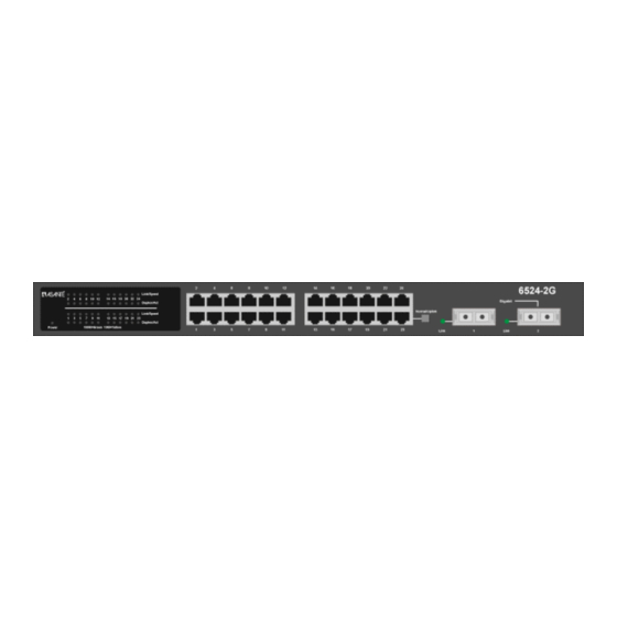
Figure 1-1 The IntraCore 6524 front panel Figure 1-2 The IntraCore 6524 back panel Features The following table lists the major features of the IntraCore 6524 switch. Feature Description ASIC-Based Architecture ASIC-based packet processing provides wire speed performance on all interfaces. - Page 14 Web Based Management Built-in Web-based interface is provided for chassis management, module management, port-level control, and monitoring. The IntraCore 6524 can also be managed via Telnet, Console, or third party SNMP console. VLANs Supports up to 64 port-based VLANs (IEEE 802.1Q compliant) for security, logical network design, and the control of broadcast traffic.
-
Page 15: Defaults And Specifications
Defaults and Specifications Defaults and Specifications The IntraCore 6524 is shipped with the following factory default settings and specifications: Configuration Default Setting Backplane Speed 6.4Gbps. Switching Method Store-and-forward Forwarding Rates: Switched 10Mbps = 14,880 pps (64 byte packets) Switched 100Mbps = 148,810 pps... -
Page 16: Leds
Introduction LEDs The following indicator lights are used on the IntraCore 6524. Color and Meaning Power Green - Power is on when lit Link/Speed Green - 100Mbps Amber - 10Mbps Duplex/Activity Green -Full Duplex Amber - Half Duplex Blinking - Active... -
Page 17: Installation And Setup
IntraCore 6524 for management, either from a console, via telnet, via SNMP, or by using a Web browser. Installation Guidelines The following guidelines will help you prepare to install your IntraCore 6524 in such a way that it has the proper power supply and environment. Power Requirements The source electrical outlet should be installed near the IntraCore 6524 and easily accessible. -
Page 18: Cooling And Airflow
IntraCore 6524. Installation Overview The table below shows the steps to install the IntraCore 6524. The steps that are optional are labeled “optional” and the steps that are required are labeled “required.” The sections that follow explain each step in detail. -
Page 19: Chassis Installation/Placement
Chassis Installation/Placement Chassis Installation/Placement The IntraCore 6524 can be installed in a standard 19-inch equipment rack. It can also be placed on a stable horizontal surface. The equipment rack or desk on which you install your IntraCore 6524 must be secure and stable. Equipment racks must be fastened to the floor;... -
Page 20: Free-Standing/Desktop Placement
Free-Standing/Desktop Placement The IntraCore 6524 has four rubber feet on the bottom of the case that allow for free-standing placement of the unit. For free-standing/desktop placement: Attach the four rubber pads (supplied) to the bottom of each corner of the IntraCore 6524 case. -
Page 21: Installing Gbic Interfaces
Chassis Installation/Placement Installing GBIC Interfaces If you have installed Gigabit Ethernet switch modules, you must install GBIC interfaces. Instructions for installing, removing, and maintaining GBIC interfaces are provided in this section. GBICs are hot-swappable. Note: Installing a GBIC To install a GBIC interface into a Gigabit Ethernet module: Remove the GBIC from its protective packaging. -
Page 22: Connecting Power
The most common source of contaminants in the optical bores is debris picked up from the optical connectors. Connecting Power To connect power to the IntraCore 6524, use the following procedure: Important! Carefully review the power requirements on page 2-1 before connecting power to the IntraCore 6524. -
Page 23: Connecting To The Network
Connecting to the Network Connecting to the Network The IntraCore 6524 unit may be connected to an Ethernet network, with the unit either powered on or off. Use the following procedure to make your network connections. Connect network devices to the IntraCore 6524, following the cable guidelines outlined below. -
Page 24: 1000Basex Ports Cabling Procedures
Table 2-4 1000BaseX cabling requirements Configuring for Management To use the IntraCore 6524 as a managed switch, the IntraCore 6524 must be configured with an IP address. You can accomplish this configuration in one of two ways: automatically using BootP (default) manually via the unit’s Console port... -
Page 25: Connecting To A Console
For more information, see Chapter 3, “Configuration.” To verify that a valid IP address was received, try to ‘ping’ the IntraCore 6524. If you can access the IntraCore 6524, it is properly configured with an IP address. -
Page 26: Management Options
SNMP-based network management application Table 2-5 Management Methods The rest of this section describes how to connect to the IntraCore 6524 using either out-of-band or in-band management. Out-of-Band Management Out-of-band network management allows you to configure, manage, and monitor the IntraCore 6524 and all of the installed modules. You can perform... -
Page 27: In-Band Management
Management Interface Connecting with any SNMP-based network management applica- tion and using its interface To manage the IntraCore 6524 via in-band management, use the following procedure: Make sure the network to which the IntraCore 6524 is con- nected is functioning. - Page 28 For information on managing the IntraCore 6524 with SNMP-based management software, refer to Chapter 4, “Advanced Management,” and your SNMP software manual. The Asanté private MIB for the IntraCore 6524 is available from the Asanté ftp site, ftp://ftp.asante.com/MIBS/, or you can copy it from the Installation CD- ROM.
-
Page 29: Configuration
Configuration This chapter describes how to manage the IntraCore 6524 using the Local Management Interface via an out-of-band console connection or an in-band telnet connection. This chapter contains the following sections: Local Management Interface Viewing General Information Configuration Menu System Administration Configuration System IP Configuration... -
Page 30: Local Management Interface
The Local Management Interface can be accessed via two methods: Out-of-band connection to the Console port In-band connection via Telnet (four sessions maximum) For instructions on how to connect to the IntraCore 6524, see “Management Options” on page 2-10. The rest of this chapter describes the Local Management Interface. -
Page 31: Main Menu
Local Management Interface Main Menu After logging in, the Main Menu appears, as shown in Figure 3-1. ================================================================= IntraCore 6524 Local Management System Version 1.02D Compiled Date: Jun 23 2000 19:53:29 Asante Technologies, Inc. Copyright (c) 1999 Asante Technologies, Inc. -
Page 32: Viewing General Information
Viewing General Information The General Information Screen displays the current operating information of the IntraCore 6524, such as its name, IP address, and boot information. To view General Information, type g from the Main Menu. A screen similar to Figure 3-2 appears. - Page 33 System Location The physical location of the IntraCore. System Contact Person responsible for configuration of the unit. MAC Address The hardware address of the IntraCore 6524; this address cannot be changed IP Address The unit’s IP (Internet Protocol) address. Subnet Mask The IP subnet mask for the IntraCore 6524.
-
Page 34: Configuration Menu
System Administration Displays and allows you to change the name, location, and contact Configuration information for the IntraCore 6524. See page 3-8. System IP Configuration Displays and allows changing the IP Address of the IntraCore 6524. This address is for network access to the switch. -
Page 35: Configuration Menu
System Log Allows you to view a record of any major system events or errors that have occurred on the IntraCore 6524. See page 3-45 User Interface Configu- Allows you to set the idle time-out period and password for console ration and telnet access, and enable or disable HTTP access. -
Page 36: System Administration Configuration
Configuration System Administration Configuration The System Administration Configuration Menu displays and allows you to change the name of the IntraCore 6524, its location, and the contact information. To access the System Administration Configuration Menu, type a in the Configuration Menu. A screen similar to Figure 3-4 appears. -
Page 37: Changing System Administration Info
System Administration Configuration Changing System Administration Info To change the name, location, or contact information for the IntraCore 6524, use the following procedure: Open the System Administration Configuration Menu by typing a in the Configuration Menu. Type the command letter of the item to be changed in the System Administration Configuration Menu. -
Page 38: System Ip Configuration
System IP Configuration The System IP Configuration Menu displays and allows you to change the information needed to access the IntraCore 6524 over the network via in-band management. To access the System IP Configuration Menu, type i in the Configuration Menu. -
Page 39: Changing System Ip Information
System IP Configuration Changing System IP Information To change the IP address, subnet mask, or default router of the IntraCore 6524, use the following procedure: Open the System IP Configuration Menu by typing i in the Configuration Menu. Type the command letter of the option you want to change. -
Page 40: Bootstrap Configuration
Return to previous menu Command> Figure 3-6 Local Bootstrap Configuration Menu When the IntraCore 6524 is powered on, it loads its software via one of two methods: locally (via its internal flash memory, which is the default setting) or remotely over the network. -
Page 41: Loading Software Remotely
Image resides. The IntraCore 6524 is set to load software locally from its flash memory. This occurs whenever the unit is powered on or reset. - Page 42 The method for requesting the image file from the network. This option is available only if you have selected Remote Load Mode. BootP-TFTP — Sets the IntraCore 6524 to request an IP address from a BootP server AND to download the software’s image file through TFTP (Trivial File Transfer Protocol).
- Page 43 Remote, type l. The Local Bootstrap Configura- tion Menu appears, as shown in Figure 3-6. The IntraCore 6524 is now set to download its software remotely from the network. This will occur the next time the unit is powered on or reset.
-
Page 44: Snmp Configuration
For further details on using SNMP and RMON for remote management of your network, see Chapter 4, “Advanced Management.” Important! Be sure to change the SNMP community strings in order to prevent unauthorized access to manage- ment information. IntraCore 6524 SNMP Configuration Menu SNMP Read Community: public SNMP Write Community: private... -
Page 45: Current Settings
Table 3-6 SNMP Settings Changing Community Strings To change the IntraCore 6524 community strings, use the following procedure: Open the SNMP Configuration Menu by typing n in the Configuration Menu. To change the read community string, type r. To change the write community string, type w. -
Page 46: Enabling Authentication Traps
They alert you when someone attempts to read or change data without the proper community string. To set the IntraCore 6524 to generate traps, use the following procedure: Open the SNMP Configuration Menu by typing n in the Configuration Menu. -
Page 47: Deleting A Trap Receiver
SNMP Configuration Deleting a Trap Receiver Use the following procedure to delete a trap receiver you have previously designated: Open the SNMP Configuration Menu by typing n in the Configuration Menu. Type d to Delete a Trap Receiver. A prompt for the entry of the trap receiver appears. -
Page 48: Port Configuration
Configuration Port Configuration The Port Configuration Menu allows you to manually configure each port of the IntraCore 6524 for port speed, duplex, and auto-negotiation. It also provides an overview of the entire IntraCore 6524 system’s port operating status. To access the Port Configuration Menu, type p in the Configuration Menu. A screen similar to Figure 3-9 appears. -
Page 49: Viewing Legends For Configuration Settings
Port Configuration Viewing Legends for Configuration Settings To see legends explaining the symbols used for both the Basic and Global Port Configuration Menu settings, type h. A screen appears, as shown in Figure 3-10. Legends for port status: Legends for port speed & duplex: X - Absent f - 10 Mbps &... -
Page 50: Current Port Settings
Configuration Current Port Settings The current module and port for which statistics are displayed is shown in the top right corner of the Port Configuration Menu. Table 3-7 describes each setting on the Port Configuration Menu. Setting Description Module Number The number of the module of which the selected port is a mem- ber. -
Page 51: Enabling Or Disabling A Port
Port Configuration Enabling or Disabling a Port The enabling or disabling of a port is a manual operation that can be used to isolate a network device that might be causing problems on the network, or to prevent unauthorized use of a port or station. To enable or disable a port, use the following procedure: Access the Port Configuration Menu by typing p in the Configuration Menu. -
Page 52: Configuring A Port Manually
Configuration Configuring a Port Manually If you have changed the Auto Negotiation status of a port to Manual, as described in the previous section, you can toggle the link speed from 10Mbps to 100Mbps and back, and toggle the port from half to full duplex and back. Toggling Port Link Speed Use the following procedure to toggle the port’s link speed: Access the Port Configuration Menu by typing p in the... -
Page 53: Configuring 1000Basex Ports
Port Configuration Configuring 1000BaseX Ports Because 1000BaseX ports are always in full duplex mode, the only configuration option for 1000BaseX ports is enabling and disabling the port. Enabling or Disabling a Port Enabling or disabling a port is a manual operation. You can enable or disable a port to isolate network devices that may be causing problems on the network or to prevent unauthorized use of a port or station. -
Page 54: Advanced Port Configuration
To access the Advanced Port Configuration Menu, from the Port Configuration Menu, type a. The Advanced Port Configuration Menu appears, as shown in Figure 3-11. IntraCore 6524 Advanced Port Config Menu Module: [1] Port: [01] Operating Status: +------- -------- -------- --... -
Page 55: Current Settings
Advanced Port Configuration Current Settings The settings shown in the top portion of the Advanced Port Configuration Menu are described in Table 3-8. Setting Description Module Number The number of the module of which the selected port is a mem- ber. -
Page 56: Setting Port Class Of Service
Configuration To select the port for which you want to enable or disable flow control, type s, n, or p. To toggle flow control for the selected port, type f. In the Advanced Port Configuration Menu, the Flow Control symbol for the selected port reflects its change in state, as does the 802.3x Flow Control setting. -
Page 57: Global Port Configuration
Configuration Menu. From the Basic Port Configuration Menu, type g. The Global Port Configuration Menu appears, as shown in Figure 3-12. IntraCore 6524 Global Port Configuration Menu Module: [1] Port: [01] Operating Status: +------- -------- -------- -- Auto Negotiation: ******** ******** ******** **... -
Page 58: Unicast Forwarding Database Configuration
Unicast Forwarding Database Configuration The Unicast Forwarding Database Configuration Menu allows you to view and search for addresses in the MAC Forwarding Table for the IntraCore 6524. It also provides options for displaying MAC addresses and IP/MAC binding by individual port or by VLAN. -
Page 59: Current Settings
Type either a, p, or v, depending on the range of MAC addresses you want to view. Type a to display the MAC addresses learned on all ports on the IntraCore 6524. Type p to specify a port, then see the MAC addresses for that port only. -
Page 60: Searching For A Mac Address
M — multiple (associated with multiple IP addresses, as in the case of a router) I — Self (the MAC address of the IntraCore 6524) Entry Type : ( D = Dynamic , S = Static , I = Self ) -
Page 61: Setting The Mac Address Age-Out Time
This option sets the Age-Out Time for the MAC Forwarding Table. The Age-Out Time is the number of seconds that addresses remain in the table after being learned by the IntraCore 6524. The default is 300 seconds. Use the following procedure to set the MAC address Age-Out Time. -
Page 62: Port Mirroring
You can configure the Monitor Port to send either transmitted or received traffic to the Mirror Port. In the IntraCore 6524, port 13 is always the Mirror Port. You can specify any other port to be a Monitor Port, except ports 25 and 26, the two Gigabit ports in the switch. -
Page 63: Current Options
Monitor Port will be copied to the Mirror Port. Mirror Port The port that mirrors the traffic from the Monitor Port. For the IntraCore 6524, this is always port 13. Monitor Port The port being monitored. Port Traffic Monitor The type of traffic from the Monitor Port that is copied to the... -
Page 64: Specifying Port Traffic Monitor Type
Configuration Specifying Port Traffic Monitor Type To specify whether to monitor port receive traffic or port send traffic, System Port Mirroring must be enabled. After enabling port mirroring, use the following procedure to specify the Port Traffic Monitor Type: Type m in the Configuration menu to display the Port Mir- roring Configuration menu. -
Page 65: Image File Downloading Configuration
X/Y/Z modem protocol. The two subsections that follow describe downloading by each of the two protocols. When Asanté issues a new version of software for the IntraCore 6524, you can obtain it from the Asanté World Wide Web site or by contacting Asanté... -
Page 66: Image Downloading Through Tftp
Bank 2 Image Version/ The version number and compilation date of runtime code that is Date stored in memory bank 2 on the IntraCore 6524. The runtime code is currently running on this bank. Server IP IP address of network server containing software image file. - Page 67 IP address. For details, see “Changing System IP Information” earlier in this chapter. To upgrade the IntraCore 6524 software via TFTP, use the following procedure: Access the TFTP Image File Downloading Configuration Menu by typing t in the Image File Downloading Configu- ration Menu.
-
Page 68: Serial Downloading Configuration
Configuration Serial Downloading Configuration The X/Y/Z Modem Image File Downloading Menu lets you download a new software image file for the IntraCore 6524 without interrupting the current operation. To download a new image through the IntraCore 6524 management module’s serial (console) port, type x in the Image File Downloading Configuration Menu. -
Page 69: Performing A Software Upgrade
Table 3-12 X/Y/Z Modem Image File Downloading settings Performing a Software Upgrade Use the following procedure to upgrade the IntraCore 6524 software through its serial (console) port. In the Image File Download Configuration Menu, type x to open the X/Y/Z Modem Image File Downloading Menu. - Page 70 Note: The terminal on which the serial communications software is running must have the same baud rate as the IntraCore 6524 management module console. The con- nection from the terminal to the switch console port must be an RS232C straight-through cable.
-
Page 71: System Reset Configuration
“warm” reboot. It also allows you to schedule a reset up to 24 hours in advance. To reset the IntraCore 6524, type r in the Configuration Menu. A screen similar to Figure 3-21 appears. IntraCore 6524 System Reset Configuration Menu... -
Page 72: Resetting The Intracore 6524
Open the System Reset Menu by typing r in the Configura- tion Menu. Type r, d or i. Typing r resets the IntraCore 6524. Typing r resets the to its current configuration. Typing d resets the IntraCore 6524 to the factory default. Typing i resets the IntraCore 6524 to the factory default without affecting its IP and Bootstrap configuration. -
Page 73: Viewing The System Log
Viewing the System Log Viewing the System Log The IntraCore 6524 system log records and displays any major system events on the switch, such as fatal errors, plugging in or removing a module, etc. To view the system log, use the following procedure: Type l in the Configuration Menu. -
Page 74: Clearing The System Log
To display the User Interface Configuration Menu, as shown in Figure 3-24, type u in the Configuration Menu. IntraCore 6524 User Interface Configuration Menu Console UI Idle Time Out: 5 min Telnet UI Idle Time Out: 5 min HTTP Server Status: ENABLED... -
Page 75: Current Settings
User Interface Configuration Current Settings Table 3-14 describes the settings in the User Interface Configuration Menu. Setting Description Console UI Idle Time-out Duration of time the console will remain idle before returning to the Main Menu. Telnet UI Idle Time-out Duration of time the console will remain idle before closing the Telnet connection. -
Page 76: Setting Telnet Idle Time-Out Period
Use this option to change the password that the user must enter when they log in to the Local Management Interface or the Web server interface. Important! The factory default password is Asante. The password is case-sensitive. To change the current Local Management Interface or Web-based Interface password, use the following procedure: Type p in the User Interface Configuration Menu. -
Page 77: Enabling Or Disabling The Web Server
User Interface Configuration Type the new password again at the confirmation password prompt. To cancel the change in password, type ctrl-c. Press Return. The password change takes effect. Type q to return to the Configuration Menu. You will now need to enter the new password each time you log in to the Configuration Menu. -
Page 78: Viewing Statistics
Viewing Statistics Viewing statistics on a regular basis allows you to evaluate your network’s performance. You can view current statistics for the IntraCore 6524 on a per- port basis and can change your view of those statistics and the counters displayed in it. - Page 79 Viewing Statistics IntraCore 6524 Port Statistics Counters Module: 1 Port: 1 Elapsed Time Since Reset: 000:00:00:55 <Counter Name><Total> <Avg./s> <Counter Name> <Total> <Avg./s> Total RX Pkts Total RX Bytes Good Broadcast 0 Good Multicast Total TX Pkts Total TX Bytes...
- Page 80 Configuration Page 3-52...
-
Page 81: Advanced Management
This “closed path” or “bridged loop” among the networks can also start an unending packet-passing process. Important! To explain STP more effectively, the IntraCore 6524 is described as a bridge for this section of the manual. Page 4-1... -
Page 82: How It Works
Select the ports on each bridge that forward traffic, and place the redundant ports in blocking state. Enabling and Disabling STP The IntraCore 6524 is shipped with spanning tree enabled on all ports by default. To enable or disable STP on your IntraCore 6524, use the following procedure: Type c to open the Configuration Menu. -
Page 83: Configuring Spanning Tree Parameters
Spanning Tree Protocol Configuring Spanning Tree Parameters To view the Spanning Tree Configuration Menu, as shown in Figure 4-1, type s in the Configuration Menu. IntraCore 6524 Spanning Tree Configuration Menu STP Status: Enabled Bridge ID: 8000 0000948EF37B Designated Root:... -
Page 84: Maximum Age
Advanced Management Maximum Age Each bridge should receive regular configuration BPDUs from the direction of the root bridge. If the maximum age timer expires before the bridge receives another BPDU, it assumes that a change in the topology has occurred, and it begins recalculating the spanning tree. -
Page 85: Current Stp Settings
Spanning Tree Protocol Current STP Settings The following settings are displayed in the Spanning Tree Configuration Menu, as shown in Figure 4-1. Setting Description STP Status Whether spanning tree protocol is currently enabled or disabled. Bridge ID The Bridge Identifier of this bridge. The first part of the Bridge ID is the Bridge Priority. -
Page 86: Spanning Tree Port Configuration
To set the Port Priority and Port Path Cost values for STP, access the Spanning Tree Port Configuration Menu shown in Figure 4-2 by typing p in the Spanning Tree Configuration Menu. IntraCore 6524 Spanning Tree Port Config. Menu Module: [1] Port: [01]... -
Page 87: Snmp And Rmon Management
Configuration Menu. SNMP and RMON Management The Simple Network Management Protocol (SNMP) may be used to manage the IntraCore 6524. The SNMP agent supports database objects that are defined in the following management information bases (MIBs): MIB II (RFC 1213) - Page 88 RMON so that if a particular statistic (such as the number of bad frames) goes higher than a certain level, the IntraCore 6524 will send a trap to its configured trap receivers, notifying the manager of the event.
-
Page 89: Security Management
Security Management Security Management The IntraCore 6524’s security management options are summarized in Table 4-2. Security Option Description Action Duplicated IP Detection Detects the use of a single IP Detects and logs MAC (Monitoring) address by two stations. addresses of both stations and the ports they accessed. -
Page 90: Current Settings
Advanced Management To access the Security Management Menu, type t in the Configuration Menu. A screen similar to Figure 4-3 appears. IntraCore 6524 Security Management Menu Duplicated-IP Monitoring Status: Enable Duplicated-IP Trap Status: Enable Station Movement Trap Status: Disable <Cmd>... -
Page 91: Duplicated Ip Detection And Trap
Type i to toggle duplicated IP trap. Viewing a List of Duplicated IP Addresses To view a list of duplicated IP addresses that have been detected at the IntraCore 6524: From the Configuration Menu, type t to access the Security Management Menu. -
Page 92: Enabling And Disabling Station Movement Trap
Advanced Management +---------------+--------------------+-+---------------------+-+ IP Address | Owner MAC Spoofer MAC +---------------+--------------------+-+---------------------+-+ 192.203.54.222 00:00:94:00:00:01 1 00:00:94:00:00:02 192.203.54.223 00:00:94:00:00:04 3 00:00:94:00:00:02 192.203.54.224 00:00:94:00:00:05 4 00:00:94:00:00:02 End of Summary, Quit. Figure 4-4 Duplicated IP address list Enabling and Disabling Station Movement Trap The station movement trap security measure ensures that when any end station is moved from one switch port to another, an alert is sent to the designated trap receiver. - Page 93 Security Management IntraCore 6524 Port Security Configuration Menu Module: 01 Port: 01 Port Security Info: [+: Port Security Enabled, -: No Port Security, !: Port Disabled By Security] Port Security Status: [01]+------- [09]-------- [17]-------- [25]--XXXXXX Port Security Type: New Node Detection Trap[Security Level 1]...
-
Page 94: Configuring Port New Node Detection Trap
Advanced Management Configuring Port New Node Detection Trap The port new node detection trap security measure (also called “port security trap”) ensures that when any new device is connected to the secured port, an alert will be sent to the designated trap receiver. The new device is detected when it is connected to the IntraCore 6524and its MAC address is recognized as one not present in the current address table. -
Page 95: Configuring Port Lock And Intruder Lock
Security Management To enable New Node detection: From the Configuration Menu, type t to access the Security Management Menu. Type p to access the Port Security Configuration Menu, as shown in Figure 4-5. Type t to choose Toggle Port Security Trap. Type 1 to toggle the new node trap (if it is not already enabled). -
Page 96: Setting The Intruder Trap
Advanced Management Configuring Security Level 2 or Level 3 To set security level 2 (port lock) or level 3 (intruder lock) on a port: From the Configuration Menu, type t to access the Security Management Menu. Type p to access the Port Security Configuration Menu, as shown in Figure 4-5. -
Page 97: Inserting/Modifying A Port Trusted Mac Address
Type i, then follow the instructions on the screen. Resetting Security to Defaults To reset the security measures on the IntraCore 6524 to the factory defaults, access the Security Management Menu by typing t in the Configuration Menu. Then type r to reset all of the security configurations that have been changed back to the factory-set defaults. -
Page 98: Vlan Management
LAN, independent of the actual physical configuration of a network. The IntraCore 6524 supports port-based VLANs, in compliance with the IEEE 802.1Q standard. The following subsections describe the concepts and details needed to configure and manage VLANs on IntraCore switches. -
Page 99: Other Vlan Features In Intracore 6524
VLAN Management Other VLAN Features in IntraCore 6524 VLAN management security VLAN MAC address insertion and removal Console UI management of VLANs Web interface management of VLANs The management operations allowed are: Creation Deletion Name configuration VID change configuration Adding and deleting port members... - Page 100 Advanced Management A VLAN localizes flooded traffic to parts of LAN segments rather than to a whole LAN. VLANs offer a simple and efficient solution that enhances network performance, bandwidth utilization, and network security by localizing flooded traffic. Port-based VLANs are the simplest of many VLAN approaches that solve the problem of unnecessary flooding.
-
Page 101: Vlan Groups
Inter-Switch Links.”) Default VLAN The IntraCore 6524 is configured by default with a single VLAN, with VID = 1; by default, all ports on the switch are assigned to VLAN 1. By default, the ports are also in the VLAN’s untagged set, which means they send only untagged frames. - Page 102 Advanced Management VLAN Port Membership and Untagging Port members can be added to and deleted from a VLAN Group via the VLAN Management Menu (see “Configuring Static VLAN Groups” on page 4-26). When you add a port to a VLAN, you configure the port to determine its participation in the VLAN.
-
Page 103: Inter-Switch Links
VLAN Management Inter-Switch Links An inter-switch link (ISL) is a port that connects VLANS that reside on two different switches. An ISL is the means to share VLAN information between switches on a network. For example, consider the two-switch network in Figure 4-6, which connects the Ethernet segments, E-1 through E-9. - Page 104 Advanced Management if you require frames from VLANs 2 and 3 to cross the switches, the ports should have the following configuration for both switches: Receive Ingress Port VLANs Untagset PVID Frame Type Filter 802.1Q - Only Disabled V2, V3 4095 All Frames Disabled...
-
Page 105: Configuring Vlan Management
IEEE 802.1Q version number. VLAN Type Port-based or SNMP-based. Max. Supported VLAN ID The IntraCore 6524 supports 4094 VLAN IDs. Max. Supported VLANs The IntraCore 6524 supports 64 VLANs. Number of VLANs Configured Number of VLANs currently present on the switch. -
Page 106: Configuring Static Vlan Groups
Configuration Menu to access the VLAN Management Menu, then type s to access the VLAN Group Static Configuration Menu. A screen similar to Figure 4-8 appears. IntraCore 6524 VLAN Group Static Configuration Menu VLAN Index: [01] Module Port List 1... -
Page 107: Creating A Vlan
VLAN Management Current Settings Table 4-6 describes each setting on the Menu VLAN Group Static Configuration screen. Setting Description VLAN Index The VLAN Index of the VLAN group for which the information on the screen applies. The index is maintained by the system, and is not necessarily the same as the VID. - Page 108 VLAN, then type e. Follow the instructions on the screen. Enabling and Disabling Management Access The IntraCore 6524 supports configurable management access for VLANs. By default, management access is enabled, and all devices connected to the switch in a VLAN can communicate with the switch management agent.
-
Page 109: Advanced Static Vlan Configuration
Advanced Static VLAN Configuration To access the Advanced Group Static Configuration Menu, type v in the VLAN Group Static Configuration Menu. A screen similar to Figure 4-8 appears. IntraCore 6524 VLAN Group Advanced Static Config. Menu VLAN Index: [01] Module... - Page 110 Advanced Management Current Settings Table 4-6 describes each setting on the Advanced Group Static Configuration Menu screen. Setting Description VLAN Index The VLAN Index of the VLAN group for which the information on the screen applies. The index is maintained by the system, and is not necessarily the same as the VID.
-
Page 111: Configuring Vlan Port Attributes
Menu to access the VLAN Management Menu, then type p to access the VLAN Port Configuration Menu. A screen similar to Figure 4-10 appears. VLAN Port Configuration Menu ModuleType:[24-100TX/RJ45] IntraCore 6524 VLAN Port Configuration Menu Module: 01 Port: 01 Port VLAN Membership Info (+ : Member, -: Non Member): VLAN Index :... - Page 112 Table 4-8 describes each setting on the GVRP Port Configuration Menu screen. Setting Description Module The IntraCore 6524 module for which the information on the screen applies. (Always module 1.) Port The port for which the information on the screen applies.
-
Page 113: Configuring Inter-Switch Links
Configuration Menu, type f to toggle port ingress filtering. Configuring Port Receive Frame Type By default, all ports on the IntraCore 6524 receive both 802.1Q tagged frames and untagged frames. A port may be configured to receive only 802.1Q tagged frames. - Page 114 Advanced Management For each VLAN, remove the ISL port from the VLAN’s set of untagged ports. By default, when you add a port to a VLAN, the port will send tagged and untagged frames. Removing the port from the untagged set configures the port to send only tagged frames. In most cases, configure the ISL port to receive tagged frames.
-
Page 115: Displaying A Summary Of Vlan Groups
To view a summary of VLAN groups, type v in the Configuration Menu to access the VLAN Management Menu, then type d to access the VLAN Group Summary. A screen similar to Figure 4-11 appears. IntraCore 6524 VLAN Groups Summary +-----+-------+-----------+----------+----------+------------------+ |Index|VLAN ID|Mgmt Access|Created By|Sharing ID| Status... -
Page 116: Displaying A Vlan Port Summary
Resetting VLAN Configuration to Defaults To reset the security measures on the IntraCore 6524 to the factory defaults, access the VLAN Management Menu by typing v in the Configuration Menu. Then type r to reset all of the VLAN configurations that have been changed back to the factory-set defaults. -
Page 117: Multicast Traffic Management
Multicast Traffic Management Multicast Traffic Management Multicast traffic is a means to transmit a multimedia stream from the internet (a video conference, for example) without requiring a TCP connection from every remote host that wants to receive the stream. The stream is sent to the multicast address, and from there it’s propagated to all interested parties on the internet. -
Page 118: Configuring Multicast Traffic Management
The Multicast Traffic Management Menu allows you to set up group transmission. To access the Multicast Traffic Management Menu, type c in the Configuration Menu. A screen similar to Figure 4-13 appears. IntraCore 6524 IP Multicast Traffic Management Menu VLAN Index: [01] IP Multicast Forwarding Database --------------------------------... -
Page 119: Current Settings
Table 4-9 IP Multicast Traffic Management Settings Enabling and Disabling IGMP Snooping To enable or disable IGMP Snooping on the IntraCore 6524, from the Multicast Traffic Management Menu, type i to toggle the status of IGMP Snooping. Displaying a Summary of Group Addresses To display a list of multicast group addresses for the current VLAN, from the IP Multicast Traffic Management Menu, type d. -
Page 120: Multicast Forwarding Database Configuration
To access the Multicast FDB Configuration Menu, type c in the Configuration Menu to display the IP Multicast Traffic Management Menu. Then type m. A screen similar to Figure 4-16 appears. IntraCore 6524 IP Multicast FDB Configuration Menu VLAN Index: [01] IP Multicast Address: 224.90.90.90... - Page 121 Multicast Traffic Management Adding Ports to the Selected Address To add or delete ports belonging to the multicast group: Select the VLAN that contains the ports and the address. Type s and follow the instructions. Select the Multicast Group address. Type s and follow the instructions.
- Page 122 Advanced Management Page 4-42...
-
Page 123: Web Browser Management
Web Browser Management This chapter tells how to manage the IntraCore 6524 by means of a Web browser, using Web pages to monitor and configure the switch. Most of the options and functions provided by Web browser management are similar to those of the Local Management Interface. For additional details about managing the IntraCore 6524, refer to Chapter 3, “Configuration,”... - Page 124 The Web Browser Management Overview page contains a sidebar with ten management option buttons, and a view of the IntraCore front panel that displays real-time IntraCore 6524 operating information. Note: The browser pages shown in this chapter are typical of those used for the IntraCore, and settings are given only as examples.
-
Page 125: Management Buttons
Management Buttons Management Buttons The buttons on the left provide the following options: Front Panel Genl Info (General Information) Statistics Port Config (Port Configuration) Span Tree (Spanning Tree Protocol Configuration) SNMP (Simple Network Management Protocol) Addr Table (IP/MAC Address Table) VLAN (Virtual LAN Configuration) Security Duplicate IP (Duplicate IP Trap Log) - Page 126 Web Browser Management Port Selector Feature If you point the cursor to a port connector and click the mouse, a port-specific page is displayed, which shows the selected port’s configuration and traffic statistics. Figure 5-2 Port Configuration and Statistics page Page 5-4...
-
Page 127: Genl Info (General Information) Button
Genl Info (General Information) Button Genl Info (General Information) Button This button opens the IntraCore’s General Information page, as shown in Figure 5-3. The page has six sections, which are listed at the top of the page. To view another section, click a link at the top of the page or scroll down. The General Information parameters are described fully in “Viewing General Information”... -
Page 128: Statistics Button
Web Browser Management Statistics Button This button opens the Statistics page, which presents a graphical image of the IntraCore statistics, as shown in Figure 5-4. On this page, the user can view system statistics since the last system reset. For a description of the statistics counters, see “Viewing Statistics”... - Page 129 Statistics Button Reset – Clears the counters for future samplings. Counters – Displays the statistical counters of the associated view, since up or since reset, as shown in Figure 5-6 and Figure 5-7. Note: You may also view a summary of the frames per port by placing the cursor on the desired bar.
- Page 130 Web Browser Management In Figure 5-6, a summary of the counters for a port is displayed in table format. Figure 5-6 Summary of counters for a port In Figure 5-7 the counters for a port are displayed in bar graph form. Figure 5-7 Bar graph of counters for a port Page 5-8...
-
Page 131: Port Config (Port Configuration) Button
Port Config (Port Configuration) Button Port Config (Port Configuration) Button This button opens the Port Configuration page, which provides a comprehensive overview of the status of each port on the IntraCore, as shown in Figure 5-8. The configuration page for any individual port can be accessed by single clicking on the associated blue number in the right or left hand margin. -
Page 132: Span Tree (Spanning Tree) Button
Web Browser Management Span Tree (Spanning Tree) Button This button opens the Spanning Tree Protocol (STP) Configuration page, which shows the STP Configuration of the IntraCore, as shown in Figure 5-9. STP configuration is explained in Chapter 4, “Advanced Management.” Click the STP Port Configuration button to display the STP Configuration settings for each port. -
Page 133: Snmp Button
SNMP Button SNMP Button This button displays the SNMP (Simple Network Management Protocol) page, as shown in Figure 5-10. See “SNMP Configuration” in Chapter 3 for an explanation of SNMP settings. Figure 5-10 SNMP Configuration page Page 5-11... -
Page 134: Addr (Address) Table Button
Web Browser Management Addr (Address) Table Button The Addr Table button opens the MAC and IP Address Table page, which displays two tables, as shown in Figure 5-11. The top table displays the counts of IP and MAC addresses for each port. The lower table displays IP and MAC addresses for either a particular port, or all ports. -
Page 135: Vlan Button
VLAN Button This button opens the VLAN Groups page, as shown in Figure 5-12. The page shows the modules of the IntraCore 6524, and the ports that are assigned to the currently selected VLAN. For information about VLANs, see Chapter 4. -
Page 136: Vlan Configuration
Web Browser Management Figure 5-13 VLAN Port Selection page VLAN Configuration To configure a VLAN, first select a VID in the VLAN Groups page (Figure 5- 12), then click the VLAN button. This opens the V LAN Group Configuration page, as shown in Figure 5-14. options Figure 5-14 VLAN Group Configuration options Page 5-14... - Page 137 VLAN Button Creating or Modifying a VLAN To create or modify the basic attributes of a VLAN group, click the Create or Modify button in the VLAN Group Configuration dialog box. The VLAN Attributes dialog box is displayed, as shown in Figure 5-15. Figure 5-15 VLAN Attributes dialog box Enter or change the basic attributes, then click OK.
- Page 138 VLAN of which it is a member. Figure 5-16 Add/Delete Port Member dialog box To add or delete MAC addresses for devices connected to the IntraCore 6524, click the Add/Del MAC Addr button in the VLAN Group Configuration dialog box.
- Page 139 VLAN Button Figure 5-17 Add/Delete MAC Address dialog box When you have added or deleted the MAC address, the VLAN Group Configuration page is displayed again. Page 5-17...
-
Page 140: Security Button
Web Browser Management Security Button This button opens the Security page, which provides a summary of the security of each port on the IntraCore, as shown in Figure 5-18. The configuration page for any individual port can be accessed by single clicking on the associated blue number in the Module-Port column. -
Page 141: Duplicate Ip Button
Duplicate IP Button Duplicate IP Button The Duplicate IP button lights up if a Duplicate IP number has been detected on the system. Clicking the button opens the Duplicate IP Trap Log page, which, if the trap is enabled, displays a record of duplicate IP Addresses detected. - Page 142 Web Browser Management Page 5-20...
-
Page 143: Technical Support
To contact Asanté Technical Support: Telephone (800) 622-7464 (801) 566-3787 Fax-Back (800) 741-8607 E-mail support@asante.com World Wide Web Site http://www.asante.com FTP site for RMON information <ftp://ftp.isi.edu/in-notes/rfc1757.txt> Technical Support Hours 6:00 a.m. to 5:00 p.m. Pacific Standard Time USA, Monday - Friday. - Page 144 Page A-2...
-
Page 145: Mib Statistics
MIB Statistics MIB Object Definitions for Counters The following MIB objects are those for which counters are displayed in the Statistics Counters screens shown in both the console and Web interface. The definitions and references are quoted from RFC 1516. Readable Frames “This object is the number of frames of valid frame length that have been received on this port. -
Page 146: Alignment Errors
The approximate minimum time for rollover of this counter is 80 hours.” Reference: IEEE 802.3 Rptr Mgt, 19.2.6.2, aFrameCheckSequenceErrors Alignment Errors “This counter is incremented by one for each frame received on this port with the FCSError and FramingError signals asserted and CollisionEvent signal deasserted and whose OctetCount is greater than or equal to minFrameSize and less than or equal to maxFrameSize (Ref: IEEE 802.3 Std, 4.4.2.1). -
Page 147: Runts
MIB Object Definitions for Counters The approximate minimum time for rollover of this counter is 16 hours.” Reference: IEEE 802.3 Rptr Mgt, 19.2.6.2, aShortEvents Runts “This counter is incremented by one for each CarrierEvent on this port that meets one of the following two conditions. Only one test need be made. a) The ActivityDuration is greater than ShortEventMaxTime and less than ValidPacketMinTime and the CollisionEvent signal is deasserted. - Page 148 802.3 Std) while the ActivityDuration is greater than the LateEventThreshold. Such a CarrierEvent is counted twice, as both a collision and as a lateEvent. The LateEventThreshold is greater than 480 bit times and less than 565 bit times. LateEventThreshold has tolerances included to permit an implementation to build a single threshold to serve as both the LateEventThreshold and ValidPacketMinTime threshold.
- Page 149 MIB Object Definitions for Counters Total Errors “The total number of errors which have occurred on this port. This counter is the summation of the values of other error counters (for the same port), namely: rptrMonitorPortFCSErrors, rptrMonitorPortAlignmentErrors, rptrMonitorPortFrameTooLongs, rptrMonitorPortShortEvents, rptrMonitorPortLateEvents, rptrMonitorPortVeryLongEvents, and rptrMonitorPortDataRateMismatches.
- Page 150 Page B-6...
Need help?
Do you have a question about the IntraCore 6524 and is the answer not in the manual?
Questions and answers