Shure DFR11EQ Version 5 User Manual
Digital equalizer with feedback reducer, limiter and delay
Hide thumbs
Also See for DFR11EQ Version 5:
- User manual (45 pages) ,
- Guía de referencia rápida (13 pages) ,
- Quick reference manual (13 pages)
Table of Contents
Advertisement
Quick Links
Download this manual
See also:
Quick Reference Manual
Advertisement
Table of Contents

Related Manuals for Shure DFR11EQ Version 5


Summary of Contents for Shure DFR11EQ Version 5
- Page 1 DFR11EQ Version 5 Digital Equalizer with Feedback Reducer, Limiter and Delay Table of Contents...
-
Page 2: Table Of Contents
............Trademark Notifications: Shure is a registered trademark of Shure Brothers Inc. Windows is a registered trademark of Microsoft Corporation. -
Page 3: What's New In The Dfr11Eq Version 5
A total of 10 scenes may be saved onboard and accessed when Saving and Selecting Scenes using the software interface. See Limiter – The DFR11EQ Version 5’s new limiter provides a higher level of speaker and system protection by limiting the level to which the signal level can rise. See Limiter Increased Delay Capabilities –... -
Page 4: Introduction
INTRODUCTION The Shure Model DFR11EQ Version 5 is a single channel signal processor that combines an equalizer, feedback reducer, limiter and delay in a single, half-rack enclosure. The DFR11EQ is designed to be placed in a sound reinforcement signal path to allow equalization of the overall sound system response and automati- cally detect and control acoustical feedback. -
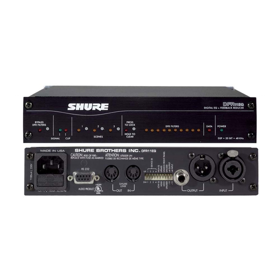
Page 5: The Dfr11Eq Hardware
DSP firmware upgrades. (Compatible with independently and either can be balanced or AMX and Crestron systems. unbalanced without affecting the other. Shure Link Interface. Allows linking of up to 16 Input Connector—Combined Shure Link devices (DFR11EQs, DP11EQs, and -Inch. Active balanced input can be used with UA888s), which may be accessed by computer. -
Page 6: Dip Switches/Shure Link Device Id
Shure Link Device ID When your DFR11EQ is linked to other Shure Link devices, each one must be assigned a unique Device ID, 0 through 15*. DIP switches 1 through 4 on the rear panel are used to set the Device ID. To change the Device ID, align the switches according to the illustrations below. -
Page 7: Dip Switch And Feedback Reducer Options - Definitions
DIP Switch/Hardware Options - Definitions High Q Filters vs. Low Q Filters The DFR11EQ offers two selections for the shape of the -octave notch filters: the High Q filter (default) and the Low Q filter. A High Q filter’s width stays very narrow as the filter depth is increased. This attenuates the minimum amount of signal possible to ensure system stability, while maintaining excellent sound quality. -
Page 8: Dfr11Eq Theory
Fixed and Dynamic Notch Filters The DFR11EQ can control the notch filters as either dynamic or fixed. Only the depth of a fixed filter may change after it is created. The position of a dynamic filter may change if there is a need detected for a new filter, such as when a hand-held microphone moves to a “hot spot”... -
Page 9: Dfr Limitations
The illustrations below demonstrate how the DFR11EQ works in a sound system. The system on the left shows a feedback loop, where the microphone picks up sound from the loudspeaker and sends it back into the sound system. The system on the right shows how an installed DFR11EQ reduces the gain on the worst case frequencies. -
Page 10: Setup For Feedback Control
Setup for Feedback Control The DFR11EQ hardware is designed to work in conjunction with the supplied software and a personal computer to offer a wide range of digital sound processing options, including feedback reduction, equalization, delay and limiting. However, the DFR11EQ may be used very effectively as a stand-alone feedback reducer without the benefit of the software or a computer. -
Page 11: Audio Connections
Audio Connections The DFR11EQ should be placed where an equalizer would be in a signal path. The following four diagrams show typical connections. Because of its utility and flexibility, the DFR11EQ can be connected in a large variety of different setups to benefit a sound system. NOTE: All cables must be shielded. - Page 12 Inserted in an Input Channel If only a single microphone is creating feedback problems, the DFR11EQ can be inserted on that channel alone. This is especially useful for wireless microphones, because the constant movement of a performer may bring the microphone too close to the sound reinforcement loudspeakers. LINE IN CHANNEL 1 IN LINE...
-
Page 13: Dfr11Eq Version 5 Software
This section describes the Version 5 Windows-based computer interface software which allows you to utilize the full features of the Shure DFR11EQ. By connecting the DFR11EQ to your computer, you can access the built-in digital equalizer, which can be configured in one of two ways: as a 30-band, -octave, constant-Q, graphic equalizer, or as a 10-band parametric equalizer. - Page 14 Accessing the DFR11EQ Version 5 Via Modem A new feature on the DFR11EQ Version 5 is the ability to remotely access installed units via a modem. To connect a unit or a network of units to allow remote modem access, follow these instructions: 1.
-
Page 15: Main Control Panel And Response Graph
Connect: Clicking the CONNECT button brings the DFR11EQ plugged in to the computer online, along with any other Shure Link networked devices. When the LED illuminates green, the connected units are online. When the LED is off, the units are operating without the computer interface and the software is running off–line. -
Page 16: Using The Frequency Response Graph
USING THE FREQUENCY RESPONSE GRAPH This section describes how to use the Frequency Response Graph, which displays a response curve showing the effect of the DFR11EQ on the audio signal. NOTE: See the Output Controls section for details on the functions of the IN/OUT meter on the right side of the Frequency Response Graph display. -
Page 17: Snapshots
2. Select Hide Response Graph... Snapshots One of the features of the DFR11EQ Version 5 software is the ability to take snapshots of a frequency response curve. A snapshot allows you to view a tracing of the original response curve while making changes. -
Page 18: Graphic Equalizer
EQUALIZER The Equalizer module of the DFR11EQ Version 5 software can be set to work as a parametric equalizer or as a graphic equalizer, according to your needs. There is an Equalizer Options window (under Options on the Main Menu Bar) for you to set the equalizer type. - Page 19 Combining vs. True -Octave Equalization Combining (default)... When the graphic equalizer is setup for combining equalization, the band filters are combined so that the response curve is smoothed out, creating a more even gradation of equalization. In the illustrations above, each showing the same section of an equalizer and the response graph, the one on the left is set to Combining mode.
- Page 20 High-Frequency Roll-Off The high frequency roll-off slider determines the corner frequency of the lowpass filter. To adjust the high frequency roll-off, drag the slider to the desired frequency. You can also use the keys on the computer keyboard to move this slider. When this slider is selected, the SLOPE field appears on the bottom of the control panel.
-
Page 21: Parametric Equalizer
Parametric Equalizer The equalizer of the DFR11EQ can be set to work as a 10-band parametric equalizer. Each filter has adjustable frequency, gain, and width. In addition, there are high- and low-frequency rolloff/shelf filters. Parametric filters are represented as dots, while the high- and low-frequency filters are represented as squares. - Page 22 NEW Button Click on the NEW button to generate a new parametric filter. Each new parametric filter initially appears at 1 KHz, 0 dB, 2/3-octave. The number of remaining filters is displayed below the NEW button. Clear Button Click on the CLEAR button to clear the filters. A dialog box will come up prompting you to clear one filter, all filters, or the entire block.
- Page 23 Cutting, Copying, and Pasting Parametric Filters Cutting a Selected Parametric Filter 1. Click on the desired parametric filter. 2. Click on Edit in the menu bar. 3. Click on Cut. Copying a Selected Parametric Filter 1. Click on the desired parametric filter. 2.
-
Page 24: Feedback Reducer
FEEDBACK REDUCER The feedback reducer section allows you to add new feedback filters or edit the frequency, depth or type of existing ones. To access the DFR control window, click on the DFR button on the Main Control Panel. Feedback Reducer Controls Lock Filters Button Click on the LOCK button to lock the filters at their current values. - Page 25 Hardware Options Window The Hardware Options window contains options for controlling DIP switches 5, 6 and 7 on the DFR11EQ hardware and setting fixed and dynamic filters. To access the Hardware Options window: 1. Click on Options in the main menu bar. 2.
-
Page 26: Delay
DELAY The DELAY section allows the user to add a delay to the outgoing signal, either as a function of time (milliseconds) or as a function of distance (inches, feet or meters). The Delay section includes the following controls: Time Delay: This field allows you to change the amount of delay in milliseconds (ms). The signal can be delayed up to 1300 ms (1.3 seconds). -
Page 27: Using Delay In Common Applications
Using Delay in Common Applications Using Delay To Correct Phase Cancellation Problems Problem: Phase cancellation can occur when two loudspeakers are near each other but not aligned. The two speakers can be seen in the illustration below. The waves represent the sound coming from each. - Page 28 Using Delay to Correct Time Alignment Problems Problem: Some larger sound systems may utilize loudspeaker fill systems. One loudspeaker may not be enough for a large hall because of power limitations. A fill loudspeaker may be placed farther in front of the main speaker to augment the sound from the main loudspeaker. This may cause the sound from the fill loudspeaker to arrive at the listener earlier than that from the main loudspeaker.
-
Page 29: Limiter
LIMITER A limiter acts as a ceiling, preventing drastic rises in the dynamic level of an audio signal. Limiting prevents the output level from exceeding the threshold setting, although occasional short peaks may still pass through the system. A limiter is often used to protect against sudden bursts which could potentially damage loudspeakers or other equipment. -
Page 30: Output Controls
OUTPUT CONTROLS Main Panel IN/OUT Level Meters OUTPUTControl Equalizer Control Window IN/OUT Level Meters The IN and OUT level meters are located next to the response graph. They display the levels of the input and output in dBu, dBFS or dBV. When the levels go into the red, the unit is near clipping. This is a useful tool for observing gain loss due to equalization settings. -
Page 31: Saving And Selecting Scenes
With the DFR11EQ Version 5, the user can select one of three saved scenes via the front panel of the DFR11EQ Version 5 hardware. This allows the user to select the three scenes most commonly used and save them so they are easily accessible through one–touch buttons. - Page 32 To Recall a Scene from Disk Once a scene has been saved, the Windows software can be used to reload that scene from disk and recall it to a DFR11EQ. To recall a scene: 1. Click on File in the main menu bar. 2.
-
Page 33: Shure Link Networks
2. Using the supplied 5-pin DIN cable, connect the Shure Link OUT of the first unit (the one connected directly to the computer) to the Shure Link IN of the second unit. Repeat this connection for each unit to be networked. -
Page 34: Maintenance
2. In the Options menu, click on Global Scene . If the Global Scene Option is active, scene changes on the unit are made to all other Shure Link devices in the network which have the Global Scene option activated. If a device does not have the Global Scene option active, it will not be affected by these changes. -
Page 35: Printing Dfr11Eq Settings
Printing DFR11EQ Settings If you are documenting a sound system, the DFR11EQ offers the option of printing out a hardcopy report showing the settings of a selected unit. To print out a hardcopy of this report: 1. Under File in the main menu bar, click on print. 2. -
Page 36: Appendix A. Specifications
APPENDIX A. SPECIFICATIONS Dimensions Frequency Response 219 mm x 137 mm x 44.5 mm 20 to 20k Hz 1.0 dB re 1 kHz in x 5 in x 1 Dynamic Range Weight 104 dB minimum, A-weighted, 20 Hz to 20 kHz 930 g (2.05 lbs) Sampling Rate FEEDBACK FILTERS... -
Page 37: Audio Connectors
Audio Connectors DFR11EQ Audio Input DFR11EQ Audio Output Connector: XLR (male) 1/4-inch Connector: XLR (female) 1/4-inch (XLR and phone plug (XLR and phone plug 1/4-inch (female) 1/4-inch (female) separate) combined) Configuration: active balanced active balanced Configuration: active balanced active balanced cross coupled cross coupled Actual... - Page 38 INFORMATION TO USER Changes or modifications not expressly approved by Shure Brothers Inc. could void your authority to operate this equipment. This equipment has been tested and found to comply with the limits for a Class B digital device, pursuant to Part 15 of the FCC Rules.
-
Page 39: Appendix B. Cables
DFR11EQ Output to Amplifier Input Mixer Sub Send to DFR11EQ Input DFR11EQ Output to Mixer Sub Return NOTE: All cables must be shielded. Except for the Shure Link cable, none of the cables shown are supplied with the DFR11EQ. XLR (male) to XLR (female) -in. -
Page 40: Digital Connectors And Cables
17 19 21 23 25 — COMPUTER 25-PIN RS-232 CONNECTOR (MALE) 9-PIN MALE — TO DFR11EQ DFR11EQ RS-232 CONNECTOR FEMALE Shure Link Cable — 5-Pin DIN Cable (MIDI-compatible cable) FUNCTION PIN # — DATA SHIELD SHURE LINK IN DATA —... -
Page 41: Appendix C. Rack Mounting The Dfr11Eq
APPENDIX C. RACK MOUNTING THE DFR11EQ The DFR11EQ comes in a -rack chassis specially designed for sturdiness. The sagging and bending found in most -rack designs is eliminated — the brackets and straddle bars are designed to ensure that the units will be installed securely. WARNING: Do not torque the screws too tightly, or the chassis may be dam- aged. -
Page 42: Appendix D. Keyboard Controls
APPENDIX D. KEYBOARD CONTROLS There are a number of keyboard controls which you can use instead of a mouse. General Controls HIGHLIGHT controls from left to right: HIGHLIGHT controls from right to left: PRESS a selected button: SAVE a scene: RECALL a scene: PRINT the settings of the current unit: EXIT the processor display:... -
Page 43: Parametric Equalizer Controls
Graphic Equalizer Controls HIGHLIGHT the sliders from left to right: RESET a selected slider: FINE ADJUST the gain of a selected slider: COARSE ADJUST the gain of a selected slider: Parametric Equalizer Controls RESET a selected parametric filter: CREATE a new parametric filter: FINE ADJUST the FREQUENCY of a parametric filter: COARSE ADJUST the FREQUENCY of a parametric filter: FINE ADJUST the GAIN of a parametric filter:...
Need help?
Do you have a question about the DFR11EQ Version 5 and is the answer not in the manual?
Questions and answers