Advertisement
Quick Links
2 2 2 HARTREY AVE.. EVANSTON. IL. 6 0 2 0 4 U.S.A.
MODEL SR107
AREA CODE 312/866.2200
CABLE: SHUREMICRO
AUDIO EQUALIZER
TWX:
9 1 0 - 2 3 1 - 0 0 4 8
TELEX: 72.4381
I
OPERATION AND SERVICE MANUAL
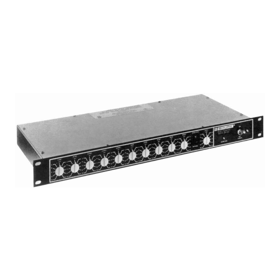
The Shure SR107 Audio Equalizer is a compact, versa-
tile unit designed to provide adjustment of tonal balance
on an octave-by-octave basis across the audio frequency
range. The SR107 is used in sound system applications
for the purposes of feedback control in live performances,
playback equalization (correcting for equipment response
and/or room acoustics in prerecorded performances), and
improvement in the sound quality of live performances.
Equipment response correction includes the elimination
of such problems as transducer incompatibility, overload
at low frequencies (rumble), tape hiss and disc surface
noise. The SR107 is a balanced input and output line level
device, designed primarily for installation between the
audio console or mixer and the power amplifier of the
sound system.
DESCRIPTION
The SR107 has ten octave band, minimum phase, com-
bining type filters centered on ISO? preferred frequencies
from 31 Hz to 16 kHz. Each filter is adjustable for ap-
proximately 15 dB of boost or attenuation. The equalized
output is adjustable over a 2 1 5 dB range, and overall
gain of up to 20 dB may be introduced to compensate for
low input signals. A peak-responding overload light-
emitting diode (LED) is provided on the front panel. The
SR107 contains both professional three-pin and phone
jack input and output connectors, and a phone jack
auxiliary output.
The SR107 is designed for maximum simplicity of op-
eration and maintenance. All components are of the high-
est quality and are operated well within their respective
ratings to assure maximum reliability under normal use
conditions.
The SR107 and SR107-2E are identical except that the
SR107 operates from 108-132 Vac, 50/60 Hz and the
SR107-2E operates from either 105-125 or 210-250 Vac,
50/60 Hz (switch-selectable). The SR107-2E is supplied
with a detachable ac line cord (without power plug). The
SR107 (only) is listed by Underwriters' Laboratories, Inc.,
and is listed by Canadian Standards Association as
certified.
All SR107 units are supplied with four rack-mounting
screws for mounting in standard 19-inch (483 mm) audio
equipment racks or in optional Shure A30A or A105A
Carrying Cases. An optional protective cover, Shure
Model A107A, is also available.
SPECIFICATIONS
*
Equipment Type
. . . . .
.All transistor inductorless active
equalizer
Voltage Gain:
GAlN Control
at UNITY
. . . . . . .
.O dB LINE INPUT to LINE OUT-
PUT
-27
dB LlNE INPUT to AUX
OUTPUT
-50
dB LlNE INPUT to MIC
OUTPUT
GAlN Control
at +20 dB
. . . . . . .
+20 dB LINE INPUT to LINE
OUTPUT
- 7 dB LlNE INPUT to AUX OUT-
PUT
-30
dB LlNE INPUT to MIC
OUTPUT
LEVEL Control
. . .
.Provides additional gain adjust-
ment of k 1 5 dB over values
given above, EQUALIZER IN
mode only.
Frequency Response
.
.%2 dB from 30 Hz to 20 kHz,
EQUALIZER IN or BYPASS
Signal to Noise Ratio
. . . . .
(20 Hz-20 kHz)
.Typically 99 dB at maximum out-
put with Filter Controls and
LEVEL Control at zero and
GAlN Control at UNITY in
EQUALIZER IN mode.
Output Noise,
Maximum
(300 HZ-20 kHz
. . .
at LINE OUTPUT)
-84 dBV (63 pV)
- 69 dBV (0.50 mV), LEVEL Con-
trol at +15, Filter Controls at
- 15
-91
dBV (28 pV), EQUALIZER
Switch in BYPASS
Output Hum and Noise,
Maximum
(20 HZ-20 kHz
at LINE OUTPUT)
. . . -
83 dBV (71 pV)
-
67 dBV (0.56 mV), LEVEL Con-
trol at +15, Filter Controls at
-15
-88
dBV (40 pV), EQUALIZER
Switch in BYPASS
lnput Common Mode
Rejection
. . . . . . . . .
.90 dB minimum at 100 Hz
Clipping Level
(30 HZ-20 kHz):
Input
. . . . . . . . . . . .
+18 dBm minimum (+15.8 dBV,
6.2V) GAlN Control at UNITY
- 2
dBm minimum (-4.2
dBV,
0.62V) GAlN Control at
+
20dB
t
International Organization for Standardization
Copyright
1979,
Shure Brothers Inc.
27Al089 (SF)
'See
Page 2
Printed in U.S.A.
Advertisement

Related Manuals for Shure SR107


Summary of Contents for Shure SR107
- Page 1 1 5 dB over values at low frequencies (rumble), tape hiss and disc surface given above, EQUALIZER IN noise. The SR107 is a balanced input and output line level mode only. device, designed primarily for installation between the Frequency Response .%2 dB from 30 Hz to 20 kHz,...
- Page 2 INPUT Connectors Measurement conditions unless otherwise specified: Operating voltage I ~ O V , 60 Hz (SR107). 230V 60 Hz with VOLTAGE SELECTOR Switch in 220V posi- phase with pin of MIC/L'NE tion ( ~ ~ 1 0 7 - 2 i ) . L I ~ E INPUT 7 volt at 1 kHz through 600 ohms. LlNE...
-
Page 3: Overload Led
Provides unbalanced UNITY. (For Link use, set GAlN Control to $20 dB.) low-impedance output for connection to audio con- 5. SR107: Connect ac line cord (15) to grounded 108- sole or amplifier-mixer link input. 132V, 50/60 Hz ac source. LlNE OUTPUT Phone Jack... - Page 4 88.9 mm (3% in.) for two SR107s supply). Maximum power consumption at either operating or one SR107 and one other unit of 44.4 mm (1% in.) voltage is 6 watts. height. The A105A has a panel height of 178 mm (7 in.)
- Page 5 The output of the second Equalizer differential ampli- The gain of the SR107 can be adjusted by means of fier is fed to the EQUALIZER IN/BYPASS Switch (2) the back panel GAlN Control from UNITY to +20 dB in which selects the input to the line output stage from either the EQUALIZER IN or BYPASS modes.
- Page 6 SR107 is sufficient to accomplish significant feedback Stage Monitor System suppression without noticeable loss of program material. In a stage monitor system the SR107 is connected be- Proper adjustment of the Equalizer for feedback control tween the audio console monitor line output (line level) is a matter of some experimentation;...
- Page 7 If the SR107 was not previously connected to the sound Usually, the analyzer equipment is used first to estab- system, refer to General Operating lnstructions for con- lish the desired house curve or preferred sound system nection and setup instructions.
- Page 8 F1 which is rated at 1/16A, 250V, Slo-Blo for the the appropriate SR107 Filter Control is used to reduce SR107 and 1/8A, 250V, Slo-Blo for the SR107-2E. If re- the system response in this area. This process is con-...
- Page 9 If either of the two Active Component Checking boards in the SR107 are to be replaced, the new board Defective transistors and diode rectifiers may be lo- assembly should be examined first to determine which cated by use of a standard ohmmeter such as a Simpson leads are already soldered in place.
- Page 10 D l -D5 90A1989 Diode Assembly, Light-Emitting Monsanto MV5023 RKC133 80A297 Fuse, AC, 1 /16A, 250V, Slo-Blo, Littelfuse 31 5.062 Pigtail (SR107) Fuse, AC, 1 /8A, 250V, Slo-Blo, Littelfuse 31 5.125 80A322 Pigtail (SR107-2E) 90R2600 Connector, Phone Jack, Switchcraft 128...
-
Page 11: Replacement Parts List
Transformer, Line and Microphone None Level Output Belden 17408 95A632 Line Cord and 3-Conductor Ac Plug Assembly (SR107) None 90A1888 Line Cord and 3-Conductor Ac Female Connector Assembly (SRl07-2E) * Parts listed as RKC Kits should be ordered by that kit number. Any orders received for piece parts where RKC Kit number is... - Page 12 REPLACEMENT PARTS LIST Continued Reference Replacement Replacement Kit Consists Of: Commercial Designation Kit No. Alternate Part No. Description Qty. AMPLIFIER (BOARD A l ) C101, (2103- 86A630 Capacitor, Electrolytic, Sprague 30D-TE- C104 4.7 or 5 , F , 35V 1303; CDE NLW-5-50 C102, C108 868629 Capacitor, Electrolytic,...
- Page 13 REPLACEMENT PARTS LIST Continued Commercial Replacement Kit Consists Of: Reference Replacement Alternate Designation Kit No. Part No. Description Qty. 50WA103 Capacitor, Mylar, CDE MFP-05S1*' C212, C225, .01 , F , +5%, lOOV C227 CDE MFD-05S33* 50WA333 Capacitor, Mylar, C214, C226 ,033 , F , *5%, lOOV CDE MFP-05P27*...
- Page 14 5. Measurements made with ac VTVM of 1 megohm General or greater input impedance. Shure part numbers are not shown in the Parts List ac- companying the Circuit Diagram (Figure 11) if parts are NOTE: Measurements of voltage (*) at collector of readily available through local electronics parts suppliers.
- Page 15 2236-31680-4 FIGURE AMPLIFIER CIRCUIT BOARD PARTS LOCATION FIGURE 10. EQUALIZER CIRCUIT BOARD PARTS LOCATION...
- Page 16 POWER X3 V D C IgO VAL L X ) / w 0 W A T T S SR107.2E POWER SUPPLY GflN FIGURE 11. SR107 AUDIO EQUALIZER CIRCUIT DIAGRAM...
- Page 17 LINE OUTPUT W A D W WlTH 600n. D.C. VOLTAGES M ~ A S U R E D WITH ZERO SIGNAL APPLIED. TAKEN WlTH KOHM ISOLATION RESISTOR AT TIP OF PROBE. ( ~ a i EQUALIZER BOARD FIGURE 11. SR107 AUDIO EQUALIZER CIRCUIT DIAGRAM...
-
Page 19: Shipping Instructions
3.5 kg (7 Ib, 12 oz). * All specifications apply to Model SR107-2E except for the Any Equalizer not meeting all of the above specifica- operating voltage range which is 105-125 or 210-250 volts, tions shall be deemed unacceptable under this specifica- 50/60 Hz ac for this model.
Need help?
Do you have a question about the SR107 and is the answer not in the manual?
Questions and answers