
Related Manuals for AOpen MX 36 LE-U


Summary of Contents for AOpen MX 36 LE-U
-
Page 1: Mx36Le-U/Mx36Le-Un
MX36LE-U/MX36LE-UN DOC. NO.: MX36LEUN-OL-E0111B... -
Page 2: Table Of Contents
’ ’ MX36LE-U/MX36LE-UN ........................1 What’s in this manual .................................2 You Must Notice ..................................8 Before You Start ..................................9 Overview ....................................10 Feature Highlight ..................................11 Quick Installation Procedure..............................14 Motherboard Map ..................................15 Hardware Installation ........................16 JP14 Clear CMOS Data ................................17 CPU Installation..................................18 JP23 Adjust FSB/PCI Clock ..............................19 CPU Jumper-less Design................................24 Setting CPU Core Voltage ................................25 CPU and Housing Fan Connector (With H/W Monitoring) ......................25... - Page 3 ATX Power Connector ................................29 IDE and Floppy Connector ...............................30 IrDA Connector ..................................33 WOL (Wake on LAN) ................................34 CNR Expansion Slot .................................36 Support Realtek 10/100 Mbps LAN onboard (MX36LE-UN Only) .....................37 JP13 LAN Enable / Disable Select Jumper (MX36LE-UN Only)....................38 JP27 USB Keyboard Wakeup ..............................39 PC99 Color Coded Back Panel..............................40 COM2 Connector..................................41 Support 2...
- Page 4 Low ESR Capacitor ..................................52 Layout (Frequency Isolation Wall) ............................54 Driver and Utility..........................55 Autorun Menu from Bonus CD Disc ............................56 Installing Windows 95 ................................57 Installing Windows 98 ................................58 Installing Windows 98 SE, Windows ME & Windows2000......................59 Installing VIA 4 in 1 Driver ................................60 Installing Onboard Sound Driver...............................61 Installing Onboard AGP Driver..............................62 Installing LAN Driver.................................63...
- Page 5 Glossary ............................83 AC97 ......................................83 ACPI (Advanced Configuration & Power Interface)........................83 AGP (Accelerated Graphic Port) ...............................83 AMR (Audio/Modem Riser) ...............................84 AOpen Bonus Pack CD ................................84 APM (Advanced Power Management) ............................84 ATA (AT Attachment).................................84 ATA/66 ......................................84 ATA/100 ....................................85 BIOS (Basic Input/Output System) ............................85 Bus Master IDE (DMA mode)..............................85...
- Page 6 EPROM (Erasable Programmable ROM) ..........................87 EV6 Bus ....................................87 FCC DoC (Declaration of Conformity)............................87 FC-PGA (Flip Chip-Pin Grid Array) ............................88 Flash ROM ....................................88 FSB (Front Side Bus) Clock..............................88 C Bus .....................................88 IEEE 1394 ....................................89 Parity Bit....................................89 PBSRAM (Pipelined Burst SRAM) ............................89 PC-100 DIMM ...................................90 PC-133 DIMM ...................................90 PCI (Peripheral Component Interface) Bus..........................90...
- Page 7 Shadow E PROM ..................................92 SIMM (Single In Line Memory Module) .............................92 SMBus (System Management Bus) ............................92 SPD (Serial Presence Detect) ..............................92 UltraATA ....................................93 USB (Universal Serial Bus)...............................93 VCM (Virtual Channel Memory) ..............................94 ZIP file ......................................94 Troubleshooting ...........................95 Technical Support........................99 Product Registration........................103...
-
Page 8: You Must Notice
All of the specifications and information contained in this manual are subject to change without notice. AOpen reserves the right to revise this publication and to make reasonable changes. AOpen assumes no responsibility for any errors or inaccuracies that may appear in this manual, including the products and software described in it. -
Page 9: Before You Start
This Online Manual will introduce to the user how this product is installed. All useful information will be described in later chapters. Please keep this manual carefully for future upgrades or system configuration changes. This Online Manual is saved format, we recommend using Adobe Acrobat Reader 4.0 for online viewing, it is included in Bonus CD disc or you can get free download from... -
Page 10: Overview
® Thank you very much for choosing AOpen MX36LE-U / MX36LE-UN, which is an Intel Socket 370 motherboard based on the microATX form factor featuring the VIA Apollo PLE133T chipset. As high performance chipset built in the M/B, the MX36LE-U / ®... -
Page 11: Feature Highlight
® ® Supports Intel Socket 370 Pentium III Tualatin/Celeron™ 533MHz~1.2GHz+ and VIA C3 800MHz+ with 66/100/133MHz Front Side Bus designed for Socket 370 technology. Chipset The VIA Apollo PLE133T is a high performance, cost-effective and energy efficient chipset for the implementation of computer system with 66/100/133MHz CPU FSB frequencies and based on 64-bit Socket 370 CPU. - Page 12 Memory The MX36LE-U / MX36LE-UN supports both PC100 and PC133 SDRAM, which allows zero wait state bursting between the DRAM and the data buffers at 66/100/133MHz. The four banks of DIMM slots can be composed of an arbitrary mixture of 1M/2M/4M/8M/16MxN DRAMs.
- Page 13 Agency (EPA) Energy Star program. It also offers Plug-and-Play, which helps save users from configuration problems, thus making to system user-friendlier. Hardware Monitoring Management Supports CPU or system fans status, temperature and voltage monitoring and alert, through the on-board hardware monitor module and AOpen Hardware Monitoring Utility. Enhanced ACPI ® Fully implement the...
-
Page 14: Quick Installation Procedure
This page gives you a quick procedure on how to install your system. Follow each step accordingly. Installing CPU and Fan Installing System Memory (DIMM) Connecting Front Panel Cable Connecting IDE and Floppy Cable Connecting ATX Power Cable Connecting Back Panel Cable Power-on and Load BIOS Setup Default Setting CPU Frequency Reboot... -
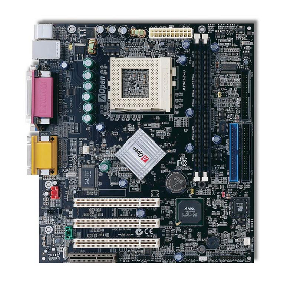
Page 15: Motherboard Map
Motherboard Map MODEM-CN Connector (Red) CD-IN Connector (Black) PC99 Colored Back Connector Onboard AC97 CODEC LAN Chip (MX36LE-UN Only) AUX-IN Connector (Green) JP27 USB Keyboard Wakeup CPUFAN Connector CNR Expansion Slot Low ESR Capacitors 370-pin CPU Socket supports 32-bit PCI Slot x3 66/100/133MHz FSB for Pentium!!! Tualatin / Celeron 533MHz~1.2GHz+ and VIA C3... -
Page 16: Hardware Installation
This chapter describes jumpers, connectors and hardware devices of this motherboard. Note: Electrostatic discharge (ESD) can damage your processor, disk drives, expansion boards, and other components. Always observe the following precautions before you install a system component. Do not remove a component from its protective packaging until you are ready to install it. -
Page 17: Jp14 Clear Cmos Data
You can clear CMOS to restore system default setting. To clear the CMOS, follow the procedure below. 1. Turn off the system and unplug the AC power. 2. Remove ATX power cable from connector PWR2. 3. Locate JP14 and short pins 2-3 for a few seconds. 4. -
Page 18: Cpu Installation
® This motherboard supports Intel Pentium III Tualatin / Celeron and VIA C3 Socket 370 CPU. Be careful of CPU orientation when you plug it into CPU socket. Pull up the CPU socket lever and up to 90-degree angle. Locate Pin 1 in the socket and look for a black dot or cut edge on the CPU upper interface. -
Page 19: Jp23 Adjust Fsb/Pci Clock
This jumper is used to specify the relationship of PCI and clock. Generally speaking, if you are not an overclocker, we recommend you to set at the default setting. FSB=66MHz FSB=100MHz FSB=133MHz Auto Detection Pin 1 (Default) JP23 FSB Select Jumper... - Page 20 PCI Clock = CPU FSB Clock / Clock Ratio Clock Ratio CPU (Host) Memory PCI x2 or x3 2X (Overclocking) 37.5 PCI x2 or x3 PCI x2 or x3 or x4 3X (Overclocking) 37.3 PCI x2 or x3 or x4 PCI x3 or x4 Warning: VIA PLE133T chipset supports maximum 133MHz FSB, higher...
- Page 21 BIOS Setup > Frequency/Voltage Control > CPU Host Clock (CPU/PCI) Core Frequency = CPU FSB Clock * CPU Ratio CPU Ratio 3x, 3.5x, 4x, 4.5x, …16x CPU FSB 66.8, 75, 83.3, 100, 103, 105, 110, 112, 115, 120, 124, 133, and 150MHz Warning: VIA PLE133T chipset supports maximum 133MHz FSB, higher clock setting may cause serious...
- Page 22 Tip: If your system hangs or fails to boo t Core Frequency = CPU Clock * CPU Ratio because of overclocking, simply use <Home> key to restore the default setting. Home CPU Core FSB Clock Ratio Frequency Celeron 533 533MHz 66MHz Celeron 566 566MHz...
- Page 23 Pentium III 850E 850MHz 100MHz 8.5x Pentium III 533EB 533MHz 133MHz Pentium III 600EB 600MHz 133MHz 4.5x Pentium III 667EB 667MHz 133MHz Pentium III 733EB 733MHz 133MHz Pentium III 800EB 800MHz 133MHz Pentium III 866EB 866MHz 133MHz Pentium III 933EB 933MHz 133MHz Pentium III 1G...
-
Page 24: Cpu Jumper-Less Design
CPU VID signal and SMbus clock generator provide CPU voltage auto-detection and allows the user to set the CPU frequency through the BIOS setup, therefore no jumpers or switches are used. The disadvantages of the Pentium based jumper-less designs are eliminated. There will be no worry of wrong CPU voltage detection. Clock Generator Intel Socket 370... -
Page 25: Setting Cpu Core Voltage
This motherboard supports CPU VID function. The CPU core voltage will be automatically. It is not necessary to set CPU Core Voltage. Plug in the CPU fan cable to the 3-pin CPUFAN connector. If you have housing fan, you can also plug it on FAN2 connector. +12V SENSOR CPUFAN... -
Page 26: Dimm Socket
This motherboard has two 168-pin DIMM sockets that allow you to install PC100 PC133 memory up to 1.0GB. DIMM1 DIMM2... -
Page 27: Front Panel Connector
Attach the power LED, EMPI, speaker, power and reset switch connectors to the corresponding pins. If you enable “Suspend Mode” item in BIOS Setup, the ACPI & Power LED will keep flashing while the system is in suspend mode. Locate the power switch cable from your ATX housing. It is 2-pin female connector from the housing front panel. -
Page 28: Ac Power Auto Recovery
Attach the power LED, speaker, and reset switch connectors to the corresponding pins. If you enable Power Management Setup > ACPI Suspend Type in BIOS Setup, the ACPI & Power LED will keep flashing while the system is in suspend mode. Suspend Type ACPI LED Power on Suspend (S1) -
Page 29: Atx Power Connector
The ATX power supply uses 20-pin connector shown below. Make sure you plug in the right direction. +12V 5VSB PW-OK PS-ON +3.3V -12V +3.3V +3.3V... -
Page 30: Ide And Floppy Connector
Connect 34-pin floppy cable and 40-pin IDE cable to floppy connector FDC and IDE connector. The blue connector is IDE1 for clear identification. Be careful of the pin1 orientation. Wrong orientation may cause system damage. Primary Primary Master (1st) Slave (2nd) IDE1 (Primary) IDE2 (Secondary) Pin 1... - Page 31 IDE1 is also known as the primary channel and IDE2 as the secondary channel. Each channel supports two IDE devices that make a total of four devices. In order to work together, the two devices on each channel must be set differently to Master and Slave mode.
- Page 32 This motherboard supports Ultra ATA33, ATA66 ATA100 IDE devices. Following table lists the transfer rate of IDE PIO and DMA modes. The IDE bus is 16-bit, which means every transfer is two bytes. Mode Clock Period Clock Count Cycle Time Data Transfer Rate PIO mode 0 30ns...
-
Page 33: Irda Connector
The IrDA connector can be configured to support wireless infrared module, with this module and application software such as Laplink or Windows 95 Direct Cable Connection, the user can transfer files to or from laptops, notebooks, PDA devices and printers. This connector supports HPSIR (115.2Kbps, 2 meters) and ASK-IR (56Kbps). Install the infrared module onto the IrDA connector and enable the infrared function from BIOS Setup, UART2 Mode, make sure... -
Page 34: Wol (Wake On Lan)
This feature is very similar as Wake On Modem, but it goes through local area network. To use Wake On LAN function, you must have a network card with chipset that supports this feature, and connect a cable from LAN card to motherboard WOL connector. The system identification information (probably IP address) is stored on network card and because there is a lot of traffic on the Ethernet, you need to install network management software, such as ADM, for the checking of how to wake up the system. - Page 35 WOL Connector (Ethernet Card Side) WOL Connector (Motherboard Side) Note: These pictures are for example only; it may not be exactly the same as the motherboard you purchased.
-
Page 36: Cnr Expansion Slot
(Communication and Network Riser) is a riser card specification to replace the AMR (Audio / Modem Riser) that supports V.90 analog modem, multi-channel audio, and phone-line based networking. Owing to CPU computing power getting stronger, the digital processing job can be implemented in main chipset and share CPU power. The analogy conversion (CODEC) circuit requires a different and separate circuit design, which is put on CNR card. -
Page 37: Support Realtek 10/100 Mbps Lan Onboard (Mx36Le-Un Only)
This motherboard has a fast Ethernet controller on chip. On the strength of Realtek 10/100 LAN onboard, which is a highly-integrated Platform LAN Connect device, it provides 10/100M bps Ethernet for office and home use, the Ethernet connector is located on top of USB connectors. -
Page 38: Jp13 Lan Enable / Disable Select Jumper (Mx36Le-Un Only)
This jumper allows you to enable or disable the LAN onboard function by adjusting the position of yellow cap. Pin 1 Enable Disable... -
Page 39: Jp27 Usb Keyboard Wakeup
This jumper allows you to enable or disable the function of system wakeup through USB keyboard. To enable this function by setting the jumper to pin 2-3, you can resume your system from suspend mode when an USB keyboard is used. Pin1 Enable Disable... -
Page 40: Pc99 Color Coded Back Panel
The onboard I/O devices are PS/2 Keyboard, PS/2 Mouse, COM1 and 15-pin D-Sub connector, Printer, four USB, AC97 sound and game ports. The view angle of drawing shown here is from the back panel of the housing. LAN Connector SPP/EPP/ECP MIDI/Game Port PS/2 Mouse (MX36LE-UN Only) -
Page 41: Com2 Connector
This motherboard provides two serial ports. One of them are on back panel connector, the other is on the up-middle area of this motherboard. With proper cable, you can connect it to the back panel of chassis. Pin 1 DCD# SOUT DTR# DSR#... -
Page 42: Support 2 Nd Usb Port
This motherboard supports four USB ports. Two of them are on back panel connector, the other two are on the left-bottom area of this motherboard. With proper cable, you can connect them to front panel. Pin 1 SBD3- SBD2- SBD3+ SBD2+... -
Page 43: Cd Audio Connector
This black connector is used to connect CD Audio cable from CDROM or DVD drive to onboard sound. -
Page 44: Modem Audio Connector
This connector is used to connect Mono In/Mic Out cable from internal modem card to onboard sound circuit. The pin 1-2 is Mono In, and the pin 3-4 is Mic Out. Please note that there is no standard for this kind of connector yet, only some internal modem cards implement this connector. -
Page 45: Aux-In Connector
This GREEN connector is used to connect MPEG Audio cable from MPEG card to onboard sound. -
Page 46: Front Audio Connector
If the housing has been design with an audio port on the front panel, you’ll be able to connect onboard audio to front panel through this connector. Front Audio Connector Pin 1 FP_MIC FP_VREF PHONE_R PHONE_L... -
Page 47: Battery-Less And Long Life Design
This Motherboard implements Flash ROM and a special circuit that allows you to save your current CPU and CMOS Setup configurations without the need of a battery. The RTC (real time clock) can also keep running as long as the power cord is plugged. -
Page 48: Over-Current Protection
The Over Current Protection was very popular implemented on ATX 3.3V/5V/12V switching power supply. However, the new generation CPU uses different voltage that has regulator to transfer 5V to CPU voltage (for example, 2.0V), and makes 5V over current protection useless. This motherboard is with switching regulator onboard supports CPU over-current protection; in conjunction with 3.3V/5V/12V power supply provide the full line over-current protection. - Page 49 CPU, memory, HDD, add-on cards installed on this motherboard may be damaged because of component failure, human operating error or unknown nature reason. AOpen cannot guarantee the protection circuit will always work perfectly.
-
Page 50: Hardware Monitoring
This motherboard implements a hardware monitoring system. As you turn on your system, this smart design will continue to monitor your system’s working voltage, fan status and CPU temperature. If any of these systems’ status goes wrong, there will be an alarm through the AOpen Hardware Monitoring Utility to warn the user. -
Page 51: Resettable Fuse
Traditional motherboard has fuse for Keyboard and port to prevent over-current or shortage. These fuses are soldered onboard that when it is broken (did the job to protect motherboard), user still cannot replace it and the motherboard is still malfunction. With expensive Resettable Fuse, the motherboard can back to normal function after fuse did the protection job. -
Page 52: Low Esr Capacitor
The quality of low ESR capacitor (Low Equivalent Series Resistance) during high frequency operation is very important for stability of CPU power. The location of where to put these capacitors is another know-how that requires experience and detail calculation. - Page 53 The power circuit of the CPU core voltage must be checked to ensure system stability for high speed CPUs (such as the new Pentium III, or when overclocking). A typical CPU core voltage is 2.0V, so a good design should control voltage between 1.860V and 2.140V.
-
Page 54: Layout (Frequency Isolation Wall)
CPU working in stable condition. The layout of this motherboard implements AOpen’s unique design called “ Frequency Isolation Wall”. Separating each critical portion of motherboard into regions where each region operates in a same or similar frequency range to avoid cross talk and frequency interference between each region’s operations and condition. -
Page 55: Driver And Utility
There are motherboard drivers and utilities included in AOpen Bonus CD disc. You don’t need to install all of them in order to boot your system. But after you finish the hardware installation, you have to install your operation system first (such as Windows 98) before you can install any drivers or utilities. -
Page 56: Autorun Menu From Bonus Cd Disc
You can use the autorun menu of Bonus CD disc. Choose the utility and driver and select model name. -
Page 57: Installing Windows 95
Install Windows 95 OSR2 v2.1, 1212 or 1214 version and later with USB support. Otherwise, you need to install USBSUPP.EXE. Install the VIA 4 in 1 driver, which includes VIA AGP Vxd driver, VIA ATAPI Vendor Support driver and VIA registry (INF) program. -
Page 58: Installing Windows 98
Enable USB Controller in BIOS Setup > Advanced Chipset Features > OnChip USB, to make BIOS fully capable of controlling IRQ assignment. Install Window 98 into your system. Install the VIA 4 in 1 driver, which includes VIA AGP Vxd driver, IRQ Routing, VIA ATAPI Vendor Support driver and VIA registry (INF) program. -
Page 59: Installing Windows 98 Se, Windows Me & Windows2000
& & ® ® ® If you are using Windows 98 Second Edition, Windows Millennium Edition or Windows 2000, you do not need to install the 4-in-1 driver as the IRQ Routing Driver and the ACPI Registry are already incorporated into the operating system. Users with ®... -
Page 60: Installing Via 4 In 1 Driver
You can install the VIA 4 in 1 driver (IDE Bus master (For Windows NT use), VIA ATAPI Vendor Support Driver, VIA AGP, IRQ Routing Driver (For Windows 98 use), VIA Registry (INF) Driver) from the Bonus Pack CD disc Autorun menu. Note: Installing this Bus Master IDE driver may cause Suspend to Hard Drive failure. -
Page 61: Installing Onboard Sound Driver
This motherboard comes with an AC97 CODEC and the sound controller is in VIA South Bridge chipset. You can find the audio driver from the Bonus Pack CD disc Autorun menu. -
Page 62: Installing Onboard Agp Driver
VIA PLE133T chipset integrates a 2D/3D graphics accelerator, which provides AGP 4X incredible performance to access main memory at over 1GB/s. You can find the AGP driver from the autorun menu of Bonus Pack CD. -
Page 63: Installing Lan Driver
You can install LAN Driver under Windows95/98, Windows NT and Windows 2000 for Realtek RTL8139 Family PCI Fast Ethernet adapter by following steps. - Page 64 Installing driver procedure on Microsoft Windows 95 : ----------------------------------------------------- 1. Select "Driver from disk provided by hardware manufacturer" when being asked which driver you would like to install. 2. Specify the setup file pathname [CD-ROM]:Driver\LAN\RTL8100\Windows\Win95\WIN95A (for Windows 95 and Win95A) or [CD-ROM]:Driver\LAN\RTL8100\Windows\Win95 (for Windows 95 OSR2).
- Page 65 Installing driver procedure on Microsoft Windows NT : ----------------------------------------------------- 1. In the Main group of NT, select the "Control Panel" icon. 2. Choose the "Network" icon in the Control Panel window. 3. In the Network Settings dialog box, choose the "Add Adapter" button. The Add Network Adapter dialog box will appear.
- Page 66 NOTES: ------ * Installing Multiple LAN Adapters: Enter Windows NT and follow above setup procedure step 2,in the "Network Settings" dialog box, choose the "Configure.." button. The "Input Ethernet ID" dialog box will appear. Input adapter's Ethernet ID. Select OK and close NETWORK SETUP. Select “SKIP”...
-
Page 67: Installing Hardware Monitoring Utility
You can install Hardware Monitoring Utility to monitor CPU temperature, fans and system voltage. The hardware monitoring function is automatically implemented by the BIOS and utility software. No hardware installation is needed. -
Page 68: Acpi Suspend To Hard Drive
ACPI Suspend to Hard Drive is basically controlled by Windows operation system. It saves your current work (system status, memory and screen image) into hard disk, and then the system can be totally power off. Next time, when power is on, you can resume your original work directly from hard disk within few seconds without go through the Windows booting process and run your application again. -
Page 69: System Requirement
System Requirement AOZVHDD.EXE 1.30b or later. Delete config.sys and autoexec.bat. Fresh installation of Windows 98 on a new system 1. Execute "Setup.exe /p j" to install Windows 98 2. After Windows 98's installation is complete, go to the Control Panel > Power Management. a. - Page 70 Changing from APM to ACPI (Windows 98 only) 1. Run "Regedit.exe" a. Go through the following path HKEY_LOCAL_MACHINE SOFTWARE MICROSOFT WINDOWS CURRENT VERSION DETECT b. Select "ADD Binary" and name it as "ACPIOPTION". c. Right click and select Modify, add "01" after "0000" to make it "0000 01". d.
- Page 71 4. Run "Add New Hardware" again and it will find "Advanced Power Management Resource". 5. Click "OK". Tip: Currently we found only ATI 3D Rage Pro AGP card would support ACPI suspend to disk. Please refer to AOpen web site for latest update.
-
Page 72: Acpi Suspend To Ram (Str)
This motherboard supports ACPI Suspend to RAM function. With this function, you can resume your original work directly from DRAM without going through the Windows 98 booting process and run your application again. Suspend to DRAM saves your current work in the system memory, it is faster than Suspend to Hard Drive but requires power supplied to DRAM, while Suspend to Hard Drive requires no power. - Page 73 To implement ACPI Suspend to DRAM, please follow the procedures as below: System Requirement An ACPI OS is required. Currently, Windows 98 is the only choice. Please refer to ACPI Suspend to Hard Drive of how to setup Windows 98 ACPI mode. The VIA 4 in 1 Driver must have been installed properly.
-
Page 74: Award Bios
System parameters can be modified by going into BIOS Setup menu, this menu allows you to configure the system parameters and save the configuration into the 128 bytes CMOS area, (normally in the RTC chip or in the main chipset). To enter to BIOS setup menu, press <Del>... -
Page 75: How To Use Award™ Bios Setup Program
Award™ BIOS setup program. The following table provides details about how to use keyboard in the Award™ BIOS setup program. By the way, all products of AOpen also provides a special function in the BIOS setup, you can press <F3> key selecting preferred menu language to display. - Page 76 Load turbo setting value from CMOS. Save changed setting and exit setup program. Note: AOpen always dedicates to give users a more friendly computer system. Now, we include all function descriptions of BIOS setup program into the BIOS Flash ROM. When you select one function of BIOS setup program, the function description will appeared at right side of screen.
-
Page 77: How To Enter Bios Setup
After you finish the setting of jumpers and connect correct cables. Power on and enter the BIOS Setup, press <Del> during POST (Power-On Self Test). Choose "Load Setup Defaults" for recommended optimal performance. Warning: Please avoid of using "Load Turbo Defaults", unless you are sure your system components (CPU, DRAM, HDD, etc.) are good enough for turbo setting. -
Page 78: Bios Upgrade
By doing so, you are taking a risk of BIOS flash failure. If you indeed intent on upgrading, PLEASE BE SURE to use the right BIOS revision for the right motherboard model. AOpen Easy Flash is a little different than traditional flash method. The BIOS binary file and flash routine are linked together and you simply run a single commend to complete the flash process. - Page 79 Below are the steps for easy flashing procedures: (applies for Award BIOS ONLY) 1. Download new BIOS upgrade file from AOpen's web site. For example, MX36LEUN102.ZIP. 2. Run shareware PKUNZIP (http://www.pkware.com/) which supports miscellaneous operation systems to extract the binary BIOS file and the flash utility.
-
Page 80: Overclocking
As a leading manufacturer in motherboard industry, AOpen always listens to what customers want and develop products to fit different user's requirements. Reliability, compatibility, leading technology and friendly features are our basic goals when designing motherboards. Other than above mentioned design criteria, there are power users who are always seeking to push the limitation of the system performance by overclocking which we call them "Overclocker". - Page 81 Warning: The design of this product follows CPU and chipset vendor's design guideline. Any attempts to push beyond product specification are not recommended and you are taking your own risk to damage your system or important data. Before doing overclocking, you must make sure your components are able to tolerate such abnormal setting, especially CPU, DRAMs, hard disks, and AGP VGA cards.
-
Page 82: Vga Card & Hard Disk
VGA and HDD is key components for overclocking, for your reference, the following list are what have been successful overclocked in our lab. Please note that AOpen can not guaranty they can be successful overclocked again. Please check the Available Vendor List (AVL) by link to our official website. -
Page 83: Glossary
AGP uses both rising and falling edge of the 66MHz clock, for 2X AGP, the data transfer rate is 66MHz x 4byte x 2 = 528MB/s. AGP is now moving to 4X mode, 66MHz x 4byte x 4 = 1056MB/s. AOpen is the... -
Page 84: Amr (Audio/Modem Riser)
Unlike ACPI, BIOS controls most APM power management functions. AOpen Suspend to Hard Drive is a good example of APM power management. ATA is the specification of diskette interface. In 80’s, many software and hardware manufacturers instituted the ATA specification together. -
Page 85: Ata/100
ATA/100 is a new IDE specification under developing. ATA/100 uses both rising edge and falling edge as ATA/66 but clock cycle time is reduced to 40ns. The data transfer rate is (1/40ns) x 2 bytes x 2 = 100MB/s. To use ATA/100, you need special 80-wire IDE cable, the same as ATA/66. -
Page 86: Codec (Coding And Decoding)
Normally, CODEC means a circuit that can do digital to analog conversion and also the analog to digital conversion. It is part of AC97 sound/modem solution. DIMM socket has total 168-pin and supports 64-bit data. It can be single or double side, the golden finger signals on each side of PCB are different, that is why it was called Dual In Line. -
Page 87: Eeprom (Electronic Erasable Programmable Rom)
Also known as E PROM. Both EEPROM and Flash ROM can be re-programmed by electronic signals, but the interface technology is different. Size of EEPROM is much smaller than flash ROM. Traditional motherboard stores BIOS code in EPROM. EPROM can only be erased by ultra-violet (UV) light. If BIOS has to be upgraded, you need to remove EPROM from motherboard, clear by UV light, re-program, and then insert back. -
Page 88: Fc-Pga (Flip Chip-Pin Grid Array)
Flash ROM can be re-programmed by electronic signals. It is easier for BIOS to upgrade by a flash utility, but it is also easier to be infected by virus. Because of increase of new functions, BIOS size is increased from 64KB to 256KB (2M bit). AOpen AX5T is the first board to implement 256KB (2Mbit) Flash ROM. -
Page 89: Ieee 1394
IEEE 1394 is a low-cost digital interface originated by Apple Computer as a desktop LAN and developed by the IEEE 1394 working group. The IEEE 1394 can transport data at 100, 200 or 400 Mbps. One of the solutions to connect digital television devices together at 200 Mbps. -
Page 90: Dimm
SDRAM DIMM that supports 100MHz CPU bus clock. SDRAM DIMM that supports 133MHz CPU bus clock. Bus for the internal connection of peripheral devices, high-speed data channel between the computer and expansion card. A file format for electronic document, PDF format is independent from platform, you can read PDF file under Windows, Unix, Linux, Mac …... -
Page 91: Post (Power-On Self Test)
It is similar as PBSRAM to use burst mode transfer. SDRAM comes in 64-bit 168-pin DIMM and operates at 3.3V. AOpen is the first company to support dual-SDRAM DIMMs onboard (AP5V), from Q1 1996... -
Page 92: Shadow E 2 Prom
A memory space in Flash-ROM to simulate E PROM operation, AOpen motherboard uses Shadow E PROM for jumper-less and battery-less design SIMM socket is only 72-pin, and is only single side. The golden finger signals on each side of PCB are identical. That is why it was called Single In Line. -
Page 93: Ultraata
UltraATA (or, more accurately, UltraATA/33) is a protocol for transferring data between a hard disk drive through the computer’s data path (or bus) to the computer’s random access memory (RAM). The UltraATA/33 protocol transfers data in burst mode at a rate of 33.3MB/s, twice as fast as the previous Direct Memory Access (DMA) interface. -
Page 94: Vcm (Virtual Channel Memory)
NEC’s Virtual Channel Memory (VCM) is a new DRAM core architecture that dramatically improves the memory system’s ability to service multimedia requirements. VCM increases memory bus efficiency and performance of any DRAM technology by providing a set of fast static registers between the memory core and I/O pins. Using VCM technology results in reduced data access latency and reduced power consumption. -
Page 95: Troubleshooting
Start Turn off the power and unplug the AC power cable, then remove all of the add-on cards and cables, including VGA, IDE, FDD, COM1, COM2 and printer. Make sure if all jumper settings are correct. Clear CMOS Next... - Page 96 Continue Install the VGA card. Then connect your monitor and keyboard. Turn on the power and check if the power supply and CPU fan work properly. The problem is probably caused by power supply or motherboard failure. Next Please contact your reseller or local distributor for repairing.
- Page 97 Continue Perhaps your VGA card Check if there is display? or monitor is defective. Press <Ctrl> and <Alt> key at the same time, hold them and then press <Del> to reboot the system. It is very possible that your Check if the system keyboard is defective.
- Page 98 Continue During system rebooting, press <Del> to enter BIOS setup . Choose “Load Setup Default ”. Turn off the system and re-connect IDE cable. The problem should be Check if the system can caused reboot successfully? cable or HDD itself. Re-install the operating system such as Windows 98.
-
Page 99: Technical Support
Dear Customer, Thanks for choosing AOpen products. To provide the best and fastest service to our customer is our first priority. However, we receive numerous emails and phone-calls worldwide everyday, it is very hard for us to serve everyone on time. We recommend you follow the procedures below and seek help before contact us. - Page 100 Download Software: Check out this table to get the latest updated BIOS/utility and drivers. http://www.aopen.com/tech/download/default.htm News Group: Your problem probably had been answered by our support engineer or professional users on the news group. http://www.aopen.com/tech/newsgrp/default.htm Contact Distributors/Resellers: We sell our products through resellers and integrators.
- Page 101 The Part Number and Serial number are printed on bar code label. You can find this bar code label on the outside packing, on ISA/CPU slot or on component side of PCB. For example: Part No. Serial No. Part No. Serial No.
- Page 102 Model name and BIOS version can be found on upper left corner of first boot screen (POST screen). For example: MX36LE-UN R1.00 Sep.01.2001 AOpen Inc. Award Plug and Play BIOS Extension v1.0A Copyright © 1998, Award Software, Inc. MX36LE-UN is model name of motherboard, R1.00 is BIOS version.
-
Page 103: Product Registration
Be able to join the discussions of web-based news groups. AOpen makes sure that the information you provide is encrypted, so that it cannot be read or intercepted by other people or companies. Further, AOpen will not disclose any of information you submitted under any conditions. Please consult our... - Page 104 America Pacific Rim Europe AOpen America Inc. AOpen Inc. AOpen Computer b.v. Tel: 1-510-498-8928 Tel: 886-2-2696-1333 Tel: 31-73-645-9516 Fax: 1-408-922-2935, 1-408-432-0496 Fax: 886-2-8691-2233 Fax: 31-73-645-9604 China Germany 艾尔鹏国际上海(股)有限公司 AOpen Computer GmbH. Tel: 49-2102-157700 Tel: 49-2102-157700 Fax: 49-2102-157799 Fax: 49-2102-157799 Web Site: http:/www.aopen.com...
Need help?
Do you have a question about the MX 36 LE-U and is the answer not in the manual?
Questions and answers