Table of Contents
Advertisement
Advertisement
Table of Contents

Related Manuals for Olympus MACRO FLASH SYSTEM


Summary of Contents for Olympus MACRO FLASH SYSTEM
- Page 1 Instructions Bedienungsanleitung Mode d’emploi Instrucciones...
- Page 2 This Macro Flash System has been designed exclusively for use with Olympus digital cameras. Do not connect the Macro Flash System to a camera not manufactured by Olympus, as this may result in a malfunction or damage to the camera and/or Macro Flash System.
- Page 3 Exposure to the light from the flash at a very short range may cause irreparable injury to the eyes. Be espe- cially careful to avoid using the Macro Flash System at a distance of less than 1 meter from an infant.
- Page 4 Do not apply a strong vibration or shock to the Macro Flash System by dropping it or hitting it against something. When the Macro Flash System has not been used for a long period, mold or moss may form. This can cause a malfunction. To prevent this, it is recommended to check the operations before using the Macro Flash System after a long period of storage.
- Page 5 Olympus will not assume any liability for damages and loss of profit related to the loss of image data due to a failure of this product, servicing by a third party not designated by Olympus, or any other reason.
-
Page 6: Table Of Contents
• Checking the Package Contents ....................8 • Applicable Cameras and Lenses ....................9 • Nomenclature ..........................10 • Case for Macro Flash System ..................... 12 • Macro Flash Controller FC-1 ....................... 13 Loading batteries ......................... 13 Attaching to the camera/Removing from the camera ............14 •... -
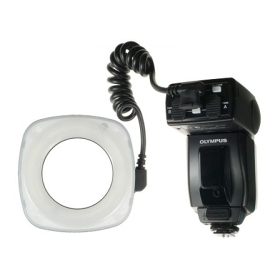
Page 7: Macro Flash System
The RF-11 Ring Flash and TF-22 must be connected to the FC-1 Macro Flash Controller for use. When an Olympus Four Thirds System digital SLR camera is used, the TTL AUTO mode can be used to optimize exposure. -
Page 8: Checking The Package Contents
CHECKING THE PACKAGE CONTENTS Check that all of the parts and accessories shown in the following table are included in the pack- age. If any item is missing or damaged, contact your dealer. Products Products Available as Sets Products Available Individually Ring Flash Set Twin Flash Set Ring Flash... -
Page 9: Applicable Cameras And Lenses
APPLICABLE CAMERAS AND LENSES Olympus Four Thirds System Digital SLR Camera E-1 The Macro Flash System can be combined with this camera together with one of the Zuiko digital lenses marked with in the following table. : Applicable. : Not applicable. -
Page 10: Nomenclature
NOMENCLATURE Macro Flash Controller FC-1 Ring Flash connector Ring Flash release (Page 15) button (Page 15) Twin Flash connector Twin Flash connector (B) (Page 27) (A) (Page 27) Twin Flash release button (Page 28) Lock ring External power connector Connect the optional HV-1 Flash High-Voltage Pack. - Page 11 Control Panel Display Twin Flash Control mode Ring Flash Twin Flash light ratio display (Pages 36& 40) Guide number (GN) Light intensity adjustment (Pages 21, 23, Setting display 35 & 39) (GN, light intensity and light intensity adjustment) Meter (Page 46) Feet (Page 46) * For simplicity, this figure shows the panel with all indicators lit.
-
Page 12: Case For Macro Flash System
Shoe ring mount (Page 41) (TF-22 flash section) (Shoe Ring SR-1) CASE FOR MACRO FLASH SYSTEM The semi-hard case can accommodate all of the Macro Flash System components. Ring Flash RF-11 Macro Flash Controller FC-1 Diffuser FDT-1 Flash Adapter Ring... -
Page 13: Macro Flash Controller Fc-1
• AA (R6) Ni-Mn batteries (ZR6 type) ........x 4 • AA (R6) lithium batteries (FR6 type) ........x 4 • Lithium battery packs (CR-V3 type) (Olympus LB-01) ..x 2 * AA (R6) manganese batteries cannot be used. How to load the batteries Open the battery compartment cover. -
Page 14: Attaching To The Camera/Removing From The Camera
<Attaching to the camera/Removing from the camera> Confirm that both the camera and Macro Flash Controller are off. Attaching or removing the Macro Flash Controller while either it or the camera is on may result in malfunction. How to attach Place the head section in the standard position (horizon- tal, front). -
Page 15: Ring Flash Rf-11
RING FLASH RF-11 <Attaching to the camera> • Attach the FC-1 Macro Flash Controller to the camera beforehand. • To prevent the Ring Flash from falling off, attach it with the camera in a stable position. While aligning the indices, attach the RF-11 Ring Flash to the lens. -
Page 16: Checking The Battery Power
<Checking the battery power> Turn the camera on and then press the Power button to MACRO FLASH CONTROLLER turn the Ring Flash on. FC-1 MODE • The [RING] indicator appears on the control panel and LAMP battery charging starts. AUTO CHECK TEST/ LIGHT... - Page 17 Approx. 160 times AA (R6) lithium batteries (FR6 type) Approx. 5 sec. Approx. 190 times Lithium battery packs (CR-V3) Approx. 4 sec. Approx. 420 times * The flash emission interval and count data were obtained from in-house tests at Olympus.
-
Page 18: Selecting The Control Mode
<Selecting the control mode> Press the Shutter button of the camera gently to start com- MACRO FLASH CONTROLLER munication of shooting information including ISO speed, FC-1 MODE lens iris and shutter speed between the camera and Macro LAMP Flash System. •... -
Page 19: Using The Illuminators
Lamp button is pressed again. AF Illuminator function With the Olympus Four Thirds System digital SLR camera, the AF illuminators can be turned on to facilitate focus adjustment when the subject is dark or lacks contrast. This function can also be defeated in the Custom Setup operation (page 46). -
Page 20: Ttl Auto
<TTL AUTO> In this mode, pre-flash is performed to measure the optimum flash light intensity and then the actual flash is emitted. See the following table and set the lens iris (F) according MACRO FLASH CONTROLLER to the lens in use. FC-1 MODE LAMP... - Page 21 Light intensity adjustment The flash light intensity can be adjusted between +3 and –3. The light intensity adjustment must be set to ON in the Cus- tom Setup operation (page 46). MACRO FLASH CONTROLLER FC-1 MODE • The indicator appears in the control panel. LAMP AUTO CHECK...
-
Page 22: Manual
MANUAL mode. When using an Olympus Four Thirds System SLR camera: • Check the light control range of the lens used and set the combination of the lens iris (F) and light intensity ratio according to the shooting distance (page 24). - Page 23 Light intensity adjustment The light intensity ratio (guide number) can be adjusted in 1/3-step increments. The light intensity adjustment must be set to ON in the Cus- MACRO FLASH CONTROLLER tom Setup operation (page 46). FC-1 MODE • The indicator appears in the control panel. LAMP AUTO CHECK...
-
Page 24: Light Control Range
< Light control range> The following charts show the light control range of the RF-11 Ring Flash with each type of lens. How to read the chart TTL AUTO Flash at optimum exposure is available by setting the lens iris (F) in the range for each shooting distance shown in the following charts. - Page 25 ZUIKO DIGITAL 14-54mm f2.8-3.5, At 14 mm Light intensity ratio ISO100 (ISO400) 1/8(1/32 The EX-25 Extension Tube 1/16(1/64 cannot be used. 1/32(1/128 1/64(1/256 F5.6 1/128( F4.0 1/256( F2.8 Shooting 0.5m 0.25m 0.22mm distance TTL AUTO light control range, with ISO 100 TTL AUTO light control range, with ISO 400 ZUIKO DIGITAL 14-54mm f2.8-3.5, At 54 mm Light intensity ratio ISO100 (ISO400)
- Page 26 ZUIKO DIGITAL ED50-200mm f2.8-3.5, At 50 mm Light intensity ratio ISO100 (ISO400) 1/1 1/4 1/2 1/8 1/1 1/4 1/4 1/16 1/2 1/8 F5.6 1/8 1/32 1/4 1/16 F4.0 1/16 1/64 1/8 1/32 F2.8 Shooting 1.2m 28cm 27.6cm distance When EX-25 Extension Tube is used.
-
Page 27: Twin Flash Tf-22
TWIN FLASH TF-22 <Attaching to the camera> • Attach the FC-1 Macro Flash Controller to the camera beforehand. Attach the SR-1 Shoe Ring (provided) to the lens. Attach the TF-22 Twin Flash to the shoe frame. Rotation ring • When removing the Twin Flash, press and hold the re- lease button on the shoe frame. - Page 28 Insert the TF-22 Twin Flash connector terminal into the Twin Flash connector on the FC-1 Macro Flash Controller until it clicks. • When unplugging the connectors, be sure to press and hold the Twin Flash release button. Be sure to attach the cap after unplugging the connectors.
-
Page 29: Checking The Battery Power
<Checking the battery power> Turn the camera on and then press the Power button to MACRO FLASH CONTROLLER turn the Twin Flash on. FC-1 MODE • The [TWIN] indicator appears on the control panel and LAMP battery charging starts. AUTO CHECK TEST/ LIGHT... - Page 30 Approx. 160 times Approx. 5 sec. Approx. 190 times AA (R6) lithium batteries (FR6 type) Lithium battery packs (CR-V3) Approx. 4 sec. Approx. 420 times * The flash emission interval and count data were obtained from in-house tests at Olympus.
-
Page 31: Selecting The Control Mode
ISO FC-1 MODE speed, lens iris and shutter speed between the camera LAMP and Macro Flash System. • The selected flash control mode is shown on the control AUTO CHECK panel. • The mode is switched every time the MODE button is... -
Page 32: Adjusting The Firing Angle
<Adjusting the firing angle> Angle of light emitting section • Adjustment at the following angles is possible in the up-down direction. Index position Angle from the horizontal position 68° Index 45° 20° Horizontal position 0° Horizontal position Down 15° Down Down 30°... -
Page 33: Using The Illuminators
Lamp button is pressed again. AF Illuminator function With the Olympus Four Thirds System digital SLR camera, the AF illuminators can be turned on to facilitate focus adjustment when the subject is dark or lacks contrast. This function can also be defeated in the Custom Setup operation (page 46). -
Page 34: Ttl Auto
<TTL AUTO> In this mode, pre-flash is performed to measure the optimum flash light intensity and then the actual flash is emitted. See the following table and set the lens iris (F) according MACRO FLASH CONTROLLER to the lens in use. FC-1 MODE LAMP... - Page 35 Light intensity adjustment The flash light intensity can be adjusted between +3 and –3. The light intensity adjustment must be set to ON in the Cus- MACRO FLASH CONTROLLER tom Setup operation (page 46). FC-1 MODE • The indicator appears in the control panel. LAMP AUTO CHECK...
- Page 36 Twin Flash light ratio setting When using both flashes ( ), you can adjust the ratio between their light intensities as required. This makes it possible to create a three-dimensional effect by applying various degrees of shading to the subject as shown below. Light ratio 8 : 1 1 : 1 1 : 8...
-
Page 37: Manual
<MANUAL> In this mode, the flash is emitted according to the light intensity setting. The control panel shows the light intensity ratio. MACRO FLASH CONTROLLER FC-1 When both of the two flashes are used, their combined MODE light intensity is displayed. LAMP Light intensity ratio: Ratio of the current light intensity with AUTO... - Page 38 MANUAL mode. When using an Olympus Four Thirds System SLR camera: • Check the TF-22 Twin Flash light control range diagram for each lens on page 42, and set the combination of the lens iris (F) and light intensity ratio according to the shooting dis- tance.
- Page 39 Light intensity adjustment The light intensity ratio (guide number) can be adjusted in 1/3-step increments. The light intensity adjustment must be set to ON in the Cus- MACRO FLASH CONTROLLER tom Setup operation (page 46). FC-1 MODE • The indicator appears in the control panel. LAMP AUTO CHECK...
- Page 40 Twin Flash light ratio setting When using both flashes ( ), you can adjust the ratio between their light intensities as required. This makes it possible to create a three-dimensional effect by applying various degrees of shading to the subject as shown below. Light ratio 8 : 1 1 : 1 1 : 8...
-
Page 41: Using The Diffuser Fdt-1
<Using the diffuser FDT-1> The diffuser enables shooting under soft lighting by attenuating the shades on the subject. Another way that shooting options are increased is the ability to use the wide-open iris (F). Insert the diffuser into the diffuser mounting grooves of the Twin Flash. -
Page 42: Light Control Range
< Light control range> The following figures show the light control range of the TF-22 Twin Flash with each type of lens. The figures assume that both flashes are used at the recommended angle (page 32). TTL AUTO Flash at optimum exposure is available by setting the lens iris (F) in the range for each shooting distance shown in the following charts. - Page 43 ZUIKO DIGITAL 14-54mm f2.8-3.5, At 14 mm Light intensity ratio ISO100 (ISO400) 1/32 1/128 The EX-25 Extension Tube 1/64 1/256 cannot be used. 1/128 1/512 1/256 F5.6 1/512 F4.0 F2.8 Shooting 0.5m 0.25m 0.22mm distance When one flash unit is used (ISO100 1/512 TTL AUTO light control range, with ISO 100 TTL AUTO light control range, with ISO 400 Light control range using one flash unit at 1/512 flash emission ratio with ISO 100...
- Page 44 ZUIKO DIGITAL ED50-200mm f2.8-3.5, At 50 mm Light intensity ratio ISO100 (ISO400) 1/1 1/4 1/4 1/16 1/2 1/8 1/8 1/32 1/4 1/16 1/16 1/64 1/8 1/32 F5.6 1/32 1/128 1/16 1/64 F4.0 1/64 1/256 1/32 1/128 F2.8 Shooting 1.2m 28cm - 278.6cm distance When EX-25 Extension Tube is used.
- Page 45 ZUIKO DIGITAL 11-22mm f2.8-3.5, At 11 mm Iris (F) Light intensity ratio ISO100 (ISO400) 1/16(1/64) The EX-25 Extension Tube 1/32(1/128) cannot be used. 1/64(1/256) 1/128(1/512) F5.6 1/256( F4.0 1/512( F2.8 Shooting 0.5m 0.25m distance : When one flash unit is used (ISO100, 1/512) TTL AUTO light control range, with ISO 100 TTL AUTO light control range, with ISO 400 Light control range using one flash unit at 1/512 flash emission ratio with ISO 100...
-
Page 46: Custom Setup
CUSTOM SETUP Custom setup allows each user to customize flash setup to suit his or her preferences. Setup procedure Turn the Macro Flash Controller on. MACRO FLASH CONTROLLER FC-1 MODE Press and hold the MODE button for more than 2 sec- LAMP onds, until the setup mode display appears in the control AUTO... -
Page 47: All Reset
ALL RESET All Reset resets the custom setups to the factory default settings. • Press the MODE and LIGHT buttons simultaneously for 2 or MACRO FLASH CONTROLLER more seconds to reset the custom setups (except for the FC-1 MODE distance display unit (m/ft)) to the default settings. LAMP •... -
Page 48: Continuous Firing
Therefore, continuous firing should be limited to the counts shown in the following tables. Do not use the Macro Flash System for at least 10 minutes after continuous firing up to the limit count. Limit counts of continuous firings... -
Page 49: Optional Accessories
Approx. 1.2 sec. Approx. 420 times • Flash emission interval and count data obtained from in-house tests at Olympus. Note Up to 40 successive full flashes are permitted. To allow the light-emitting surface to cool, the flash should not be... -
Page 50: Q&A
Does the FC-1 also turn off when the Olympus E-1 digital camera is turned off? When the Olympus E-1 Four Thirds System digital camera is turned off, the FC-1 enters the sleep mode. When the E-1 is turned on again, the FC-1 also turns on. When you want to turn off the FC-1, turn off the FC-1 before turning off the E-1. -
Page 51: Main Specifications
AA (R6) Ni-Mh batteries x 4, AA (R6) Ni-Mn batteries (ZR6) x 4, AA (R6) lithium batteries (FR6) x 4 or 3 V lithium battery pack (Olympus LB-01) x 2 External power supply : Flash High Voltage Set SHV-1 (optional) Dimensions : 78(W) x 141(H) x 119(D) mm (3.1 x 5.6 x 4.7 in.) (excluding protrusions) - Page 52 Our phone customer support is available from 8 am to 10 pm (Monday to Friday) ET E-Mail : e-slrpro@olympusamerica.com European technical Customer Support Please visit our homepage http://www.olympus-europa.com or call NUMBER : Tel.00800-67 10 83 00 (Toll-free) +49(0)1805-67 10 83 or +49(0)40-23 77 38 99 (Charged)
Need help?
Do you have a question about the MACRO FLASH SYSTEM and is the answer not in the manual?
Questions and answers