Table of Contents
Advertisement
Advertisement
Table of Contents

Subscribe to Our Youtube Channel
Related Manuals for Wheelock POWERPATH PS-12/24-8MP


Summary of Contents for Wheelock POWERPATH PS-12/24-8MP
-
Page 1: Power Supply
POWERPATH PS-12/24-8MP (103046) POWER BOOSTER POWER SUPPLY Installation Instructions 273 Branchport Avenue, Long Branch, NJ 07740-6899 Ph: (800) 631-2148 Fax: (732) 222-8707 Web Site: www.wheelockinc.com e-mail: info@wheelockinc.com A84531 B Copyright 2005 Wheelock, Inc. All rights reserved. -
Page 2: Table Of Contents
WHEELOCK INC. COMPATIBLE APPLIANCES Appendix A LIST OF FIGURES FIGURE 1: TERMINAL LOCATIONS FIGURE 2: MOUNTING DIMENSIONS FIGURE 3: POWERPATH PS-12/24-8MP FIGURE 4: OUTPUT DIP SWITCH(S) LIST OF TABLES TABLE 1: TERMINAL IDENTIFICATION TABLE 2: LED STATUS DESCRIPTION TABLE 3: DIP SWITCH SELECTION... -
Page 3: Introduction And Specifications
(used generically by any initiating circuit). Wheelock horns/strobes, strobes and horns with synchronizing capability can be utilized with the PS-12/24- 8MP. Audibles can be silenced with only two wires. Additionally, the POWERPATH can provide a temporal coded signal for appliances that can utilize it. -
Page 4: Specifications
• Compatible with 12VDC or 24VDC FACP • Signaling appliance loops are supervised and steered to either IN1 or IN2 • 2.2K Ohm, 1 Watt (Wheelock Model #MPEOL) End of Line Resistor (EOLR) for supervision of all outputs • Common input and output trouble circuits •... -
Page 5: Terminal Identification
Normal Mode, Temporal Mode, IN>OUT SYNC Mode, or TB6-3, 4 +OUT2- WHEELOCK SYNC Mode. The outputs can be configured as four Class TB6-5, 6 +OUT3- "B" circuits, two Class "A" circuits, or two Class "B" and one Class "A"... -
Page 6: Figure 1: Terminal Locations
INP2 POWER SUPPLY DC OUT3 FAULT OUT4 BATT DC POWER OUT OUTPUT1 OUTPUT3 SELECTION IN>OUT SYNC IN>OUT SYNC WHEELOCK SYNC WHEELOCK SYNC 12Vdc OR 24Vdc TEMPORAL TEMPORAL INPUT SELECT INPUT SELECT OUTPUT2 OUTPUT4 IN>OUT SYNC IN>OUT SYNC WHEELOCK SYNC WHEELOCK SYNC... -
Page 7: Led Status
1.5 LED STATUS Table 2 lists status of the LED indicators. The ALARM condition occurs when the input causes the output circuits to energize. TROUBLE condition occurs when the circuit is no longer supervised correctly. The TROUBLE LED’s for OUT1, OUT2, OUT3, OUT4 and, GND FAULT latch ON when the trouble occurs. They are turned OFF when an alarm condition occurs or the PS12/24-8MP system rest (SW8) is pressed. -
Page 8: Figure 2: Mounting Dimensions
1.060" 10.000" .544" 13.950" Figure 2: Mounting Dimensions DIMENSIONS (H x W x D) - 16” x 12.25” x 5” NOTE: All dimensions shown are measured in inches. P84333 K Sheet 8 of 23... -
Page 9: Wiring
SYNC MODE IN>OUT SYNC “ON” and strobes. : Use only with appliances that can operate using a coded horn appliance. (Example: Wheelock Series NOTE 1 CH, and Series MT) : Use only with Wheelock Series AS/AH, Series NS/NS4/NH, Series RSS and products with SL/SLM NOTE 2 strobes. -
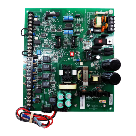
Page 10: Figure 3: Powerpath Ps-12/24-8Mp
RED + TO BE DRESSED TO BACK OF ENCLOSURE TO ENSURE POWER LIMITED V.S. NON POWER LIMITED 1/4" SEPARATION. RED + BLACK - BATTERY TERMINALS + YELLOW - TOP VIEW Figure 3: POWERPATH PS-12/24-8MP P84333 K Sheet 10 of 23... -
Page 11: Operation
Provides a temporal output for appliances that can utilize a coded signal. (i.e. single stroke bells and chimes and some horns) (NOTE: Do not use with Wheelock AS, NS, RSS appliances.) IN>OUT SYNC MODE Allows a coded signal or synchronization signal input to be utilized by the POWERPATH. -
Page 12: Class "B" Operation
CAUTION: Strobes require constant voltage and will not operate properly in the TEMPORAL MODE. A second output set in the NORMAL MODE will provide the constant voltage. CAUTION: Only use audible appliances that can use a coded signal. Do not use with Wheelock Series AS/AH, NS/NH or HS4/HS appliances. - Page 13 A second constant input with a second output set in the NORMAL MODE will provide the constant voltage. CAUTION: Only use audible appliances that can use a coded signal. Do not use with Wheelock Series AS/AH, NS/NH or HS4/HS appliances.
- Page 14 2.2K OHMS EOLR OUT4 2.2K OHMS NOTE: When using the Wheelock external Sync Module (SM or DSM), synchronization will only occur with Wheelock sync appliances. Example 6: WHEELOCK SYNC MODE without Audible Silence (CLASS B) TO NEXT APPLIANCE OUT1-4 OR EOLR IN>OUT SYNC...
-
Page 15: Class "A" Operation
2.2K OHMS • This mode will only synchronize Wheelock horns, horn strobes, and strobes with the synchronization capability. 3.4 CLASS “A” OPERATION Class “A” circuit 1 uses “OUT1” and “OUT3”. Class “A” circuit 2 uses “OUT2” and “OUT4”. When operating in Class “A”... - Page 16 A second Class “A” output set in the NORMAL MODE will provide the constant voltage for the strobe circuit. Only use audible appliances that can use a coded signal. Do not use Wheelock AS/AH or NS/NS4/NH appliances with a coded input.
- Page 17 POWERPATH - AUDIBLE OUT3 OUT4 NOTE: When using the Wheelock external Sync Module (SM or DSM), synchronization will only occur with Wheelock sync appliances. Example 12: IN>OUT SYNC MODE with External Sync Module with Audible Silence (CLASS A) SM/DSM OUT1-4...
- Page 18 TO FACP (CLASS "A") OUT4 • This mode will only synchronize Wheelock horns, horn strobes, and strobes with the synchronization capability. • If only strobes are connected to the POWERPATH outputs, the initiating input to IN2 is not required. •...
-
Page 19: Master Remote Operation
Input Selection Switch (Position 1) on OUT1 to OUT4 DIP Switches are shown in the "ON" Position allowing Input #1 to activate Outputs 1-4, Positions 2-4 are set for "WHEELOCK SYNC MODE" NOTE 3: Jumper "RET 1-" to "IN 2-" and "RET 1+" to "IN 2+ " only on the Master PS-12/24-8MP. - Page 20 Input Selection Switch (Position 1) on OUT1 to OUT4 DIP Switches are shown in the "ON" Position allowing Input #1 to activate Outputs 1-4, Positions 2-4 are set for "WHEELOCK SYNC MODE" NOTE 3: Diagram shown with an output circuit (OUT4) on Master POWERPATH used to synchronize the Remote PowerPaths.
-
Page 21: Troubleshooting
No AC power. Check AC power source. No audible output in No input to IN2+,IN2-. See Example 13 and 14 for proper WHEELOCK SYNC MODE. input connections. Horn, horn strobes, or strobes Improper MODE selection Check MODE selection. do not synchronize. -
Page 22: Battery Calculation Sheet
5.0 BATTERY CALCULATION SHEET: PS-12/24-8MP BATTERY CALCULATION SHEET STANDBY CURRENT CALCULATIONS Amps 1. The Standby Current for the PS-12/24-8MP is .060 Amps. Amps 2. Multiply by the number of hours required. 24 Hours - Multiply by 24 60 Hours - Multiply by 60 TOTAL STANDBY CURRENT IN Amp HOURS. -
Page 23: Warranty Statement
(as determined by date code). Correction of defects by repair or replacement shall be at Wheelock's sole discretion and shall constitute fulfillment of all obligations under this warranty.
Need help?
Do you have a question about the POWERPATH PS-12/24-8MP and is the answer not in the manual?
Questions and answers