Table of Contents
Advertisement
Quick Links
How to Use this Manual
This manual describes your new notebook and contains all the information you
need to set up and use the notebook. Whether you are a new or an experienced
user, you will benefit more from this manual if you are familiar with its
organization. This manual describes the PC-9300T and PC-9300D notebooks.
Unless otherwise specified, the descriptions in this manual apply to both models.
Illustrations are based on the PC-9300T notebook.
The manual is divided into five chapters, plus appendixes.
Chapter 1 Introducing the System gives a general introduction to the notebook,
explaining the main functions such as the keyboard, the indicator lamps, etc.
Chapter 2 Using the Notebook for the First Time gives the basic steps for
getting your notebook up and running.
Chapter 3 Setup Utility shows how you can make changes to the operation and
power management of the notebook by using the Setup utility.
Chapter 4 Using the Notebook describes how to carry out typical operations on
the notebook such as using the disk drives, using the GlidePoint, changing the
display, and so on.
Chapter 5 System Expansion describes how you can use the notebook's built-in
ports and connectors to add peripheral components to your system.
Appendixes provide advice on the routine care and maintenance of the notebook,
a guide to troubleshooting problems that may arise in the use of the notebook, and
detailed specifications on your notebook and the built-in ports. For your
convenience, an index is provided at the end of this manual.
In addition to this manual, you may want to consult the Windows 95 manual, and the
manuals for your software applications. The Sharp Online Manual, accessible from
the Windows 95 Start Menu, will also help your computing.
i
Advertisement
Table of Contents

Related Manuals for Sharp PC-9300


Summary of Contents for Sharp PC-9300
-
Page 1: How To Use This Manual
In addition to this manual, you may want to consult the Windows 95 manual, and the manuals for your software applications. The Sharp Online Manual, accessible from the Windows 95 Start Menu, will also help your computing. -
Page 2: Manual Conventions
Manual Conventions This manual uses different text styles to help identify different operations and functions of your notebook. Keyboard Keys When referring to specific keys on the keyboard, the key label appears in boldface as shown below: Press Enter to execute the installation. When referring to a combination of keys that are pressed simultaneously, the key labels are separated by a plus sign (+) as shown below: Pressing Ctrl + Alt + Del lets you reset your notebook. - Page 3 Section Titles/Possible Parameters In a section of text, words which represent selectable parameters, or words which refer to other sections in the manual are italicized. Select Disabled to disable the floppy disk drive. See the section Making Changes in the Main Page for more details. Notes and Cautions Icons and italic text are used for notes and cautions, to make important information stand out.
-
Page 4: Recording Information
Recording Information For future reference, please record the following information in the spaces provided below. Model Number: Serial Number: BIOS Version Number: Date of purchase: Dealer’s Name: Place of purchase: Password: The serial number is printed on a sticker located on the bottom of the notebook. You will see the BIOS Version number on the LCD screen when you turn on the notebook. -
Page 5: Unpacking The Notebook
If any of the listed accessories are missing, or if the main unit or accessories are damaged, please consult your dealer (or in case of US, a Sharp Customer Service Center at 1-800-BE-SHARP). Note: Only the PC-9300T is equipped with a fax/modem. The fax/modem... - Page 6 TranXit Quick Reference Guide This guide is an introduction to the TranXit infrared communications program and basic instructions. Sharp Import/Export User's Guide This guide is an introduction to the Import/Export infrared communications program. SuperVoice Manual (US & Canada only) (PC-9300T only) This manual explains how to use the fax/modem software.
-
Page 7: Table Of Contents
Table of Contents Preface How to Use this Manual..................i Manual Conventions .....................ii Recording Information..................iv Unpacking the Notebook..................v About System Documentation ................vi Chapter 1: Introducing the System Introduction .......................1-1 A Brief Tour of the System .................1-3 Opening the Unit ................... .. 1-3 Inside the Main Unit ..................1-4 Right-side Components ..................1-7 Left-side Components..................1-7... - Page 8 Making Changes to the Power Page ............... 3-12 System Power Management................3-13 Windows Power Management ............... 3-14 User-selectable Power Management .............. 3-14 Making Changes to the Boot Page ..............3-17 Chapter 4: Using the Notebook Power Supply..................... 4-1 Using the AC Adapter..................4-1 Using the Battery Pack...................
- Page 9 Appendixes Appendix A: System Maintenance..............A-1 Taking the Notebook on the Road ..............A-1 Cleaning the Notebook ..................A-2 Appendix B: Notes on Software ................ B-1 About the Suspend-to-disk Partition..............B-1 Memory Management Software...............B-4 Appendix C: Troubleshooting ................C-1 Appendix D: System Mapping................D-1 Memory Map ....................
-
Page 10: Chapter 1: Introducing The System
CHAPTER 1 Introducing the System This compact-size notebook computer is packed with a full range of multimedia and communications features found on a full-size desktop computer. This chapter gives general information on the system components and functions. -
Page 12: Introduction
Introduction This lightweight compact-size notebook computer has the following features. 150 MHz Pentium processor with internal cache memory, and 256K of level 2 cache memory. 16 MB EDO memory (upgradable to a maximum of 48 MB). Built-in hard disk drive and 1.44 MB floppy disk drive. Color display using either a dual scan 12.1"... - Page 13 Built-in 33.6 Kbps fax/modem with software support for voice mail, speakerphone, and telephone answering (US & Canada only) (PC-9300T only). Two Type-II or one Type-III compatible PC card slots, with Zoomed-Video support on the lower slot. Removable Nickel-Metal Hydride battery pack. A 64-bit display controller, which operates over a high-speed PCI bus and includes a video accelerator and 2 MB of video memory.
-
Page 14: A Brief Tour Of The System
A Brief Tour of the System In this section, you will learn how to locate and use the primary components of the notebook. Opening the Unit Open the display as follows. The screen locking latch is located in the center of the front edge of the notebook. -
Page 15: Inside The Main Unit
Inside the Main Unit Power Indicators Color Display Activity Indicators Stereo Speakers Keyboard Power Switch GlidePoint Microphone Color Display The PC-9300T uses an active matrix color display which has a diagonal length of 11.3". The PC-9300D uses a dual scan color display which has a diagonal length of 12.1". - Page 16 Keyboard The keyboard has 87 keys (US English) or 88 keys (others). Many functions of the notebook can be controlled by pressing special key combinations (hot keys). Stereo Speakers The speakers will output the sound that your notebook's software generates, or the sound that you input through the sound ports.
- Page 17 Activity Indicators The six activity indicators are located just above the center of the keyboard. The lamps turn on when the function that they represent is active. From left to right, the activity indicators have the following functions. CD-ROM This indicator turns on whenever the system is reading from a disc in the CD-ROM drive.
-
Page 18: Right-Side Components
Right-side Components CD-ROM Drive Infrared Port CD-ROM Drive The CD-ROM drive can be used to read from CD-ROM data discs, video discs, and audio discs. Your notebook identifies the CD-ROM drive as drive R. Infrared Port The infrared port supports the ASK infrared standard, and also the IrDA infrared standard. - Page 19 There are two Type-II PC card slots. You can also use a Type-III PC card in the lower slot. The lower slot has an integrated Zoomed Video port so that you can use PC cards that support the Zoomed Video standard (ZV cards) in the lower slot.
-
Page 20: Rear-Edge Ports
Rear-Edge Ports Expansion Game / External Connector MIDI Video Out Jack Monitor Port Port Printer Port AC Adapter RS-232C PS/2 Port Jack Serial Port The rear-edge of the notebook has two connector compartments and an AC adapter jack. You can access the connector compartments by pulling the compartment covers open. -
Page 21: Components In The Unit Base
PS/2 Port Use this port to connect your notebook to a PS/2 device such as an external keyboard or an external pointing device. Printer (Parallel) Port Use this port to establish parallel communications with another device such as a printer. Your notebook identifies the printer port as LPT1. Game/MIDI Port You can use this port to connect the notebook to a joystick or a MIDI device. -
Page 22: Chapter 2: Using The Notebook For The First Time
CHAPTER 2 Using the Notebook for the First Time This chapter explains the procedures that you should follow the first time that you use the notebook. -
Page 24: Connecting The Ac Adapter
Connecting the AC Adapter Your notebook can be powered by the internal, removable, rechargeable battery pack, or it can be connected to a wall power outlet using the supplied AC adapter. More information on the notebook's power requirements can be found in the topic Power Supply in Chapter 4. -
Page 25: System Start-Up And Shut-Down
System Start-up and Shut-down After you have connected the AC adapter, open up the screen cover by sliding the screen locking latch to the right. Press the power switch to turn on the notebook. Note: If you see the following message at the boot time, press F2, then Enter to run the Setup utility with the default values. -
Page 26: System Shut Down
You can ignore the Safe Recovery message and continue with the Windows installation. Setting the SHARP Original Wallpaper After setting up Windows 95, set the SHARP original wallpaper in the following procedure. Double-click the “Click me to set up SHARP Wallpaper” icon on the Windows desktop. -
Page 27: Using The Keyboard
Using The Keyboard The built-in keyboard has 87 keys (US English) or 88 keys (Others). About the Keyboard The layout of your notebook's keyboard is similar to a normal keyboard. In addition, there are twelve function keys, cursor control keys, and other special function keys such as Ctrl, Alt, Esc, Prt Sc, Pause, Pg Up, Pg Dn, Home and End. -
Page 28: Key Legends
Key Legends The keycaps are engraved with different legends to indicate the function of the key. Large Light-Gray Legends These represent the standard function of the key. Small Blue Legends These represent the function of the key if the Num Lock key has been pressed and the keyboard is in Num Lock mode. - Page 29 Fn + F3 This key combination decreases the volume of the audio system. Hold down the keys until the volume is correct. Fn + F4 This key combination increases the volume of the audio system. Hold down the keys until the volume is correct. Fn + F5 Each press of this key combination changes the video output of the notebook.
-
Page 30: Special Windows 95 Keys
Fn + F8 This key combination decreases the contrast of the built-in screen. Hold down the keys until the display is correct. This function only operates if you have a DSTN (dual-scan) color display. Fn + F9 This key combination increases the contrast of the built-in screen. -
Page 31: Chapter 3: Setup Utility
CHAPTER 3 Setup Utility Your notebook is installed with a Setup utility that lets you change the configuration of the system, and customize the security and power management parameters. This chapter explains how to run and use the Setup utility. -
Page 33: About The Setup Utility
About the Setup Utility Your notebook is set up correctly when it first ships. However, you might need to change the system configuration settings such as date, time, password or power management. The Setup utility consists of six menu pages: Main This page defines the basic system configuration. -
Page 34: Using The Setup Utility
Using the Setup Utility The Setup utility menu bar has six choices: Main, Advanced, Security, Power, Boot, and Exit. You can move between each of the six pages by using the left and right arrow keys. Each page has a list of items, or fields. On the right of each field there are one or more values. - Page 35 When you select this option, any changes you have made to the field values are discarded and the notebook restarts using the old values. Get Default Values When you select this option, the notebook loads the default field values. The notebook does not restart.
-
Page 36: Making Changes To The Main Page
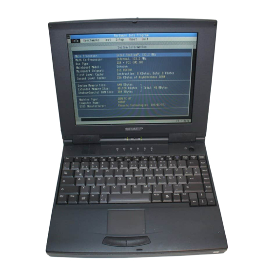
Making Changes to the Main Page The Main page of the Setup utility deals with the basic configuration of your notebook, the hardware components, the system memory, and the date and time. The illustration below shows the Main page screen. Phoeni xBI O S Setup - C opyri ght 1985 -95 Phoeni x Technol ogi es Ltd. - Page 37 Note: You can also change the time and date held by your notebook by double-clicking on the time button at the left of the Windows Task Bar. The Setup utility will automatically adjust the date and time to stay current with the changes in Windows date and time. Diskette A Use this field to disable or enable the built-in floppy disk drive.
-
Page 38: Making Changes To The Advanced Page
Making Changes to the Advanced Page The Advanced page is used to configure more advanced features in your notebook. The illustration below shows the Advanced page. Phoeni xBI O S Setup - C opyri ght 1985 -95 Phoeni x Technol ogi es Ltd. A dvanced Securi t y Pow er... - Page 39 IR Mode Use this field to make the infrared port comply with the ASK or IrDA standard for infrared communications. LPT Port This field lets you assign an address and an interrupt request number for the parallel port on the rear side of your notebook. Leave this value at the default (378, IRQ 7) unless you have a specific reason to change the address and IRQ number.
-
Page 40: Making Changes To The Security Page
Note: When you expand a 640 x 480 display to fill the whole screen, it causes some distortion to the screen fonts, and other elements of the display. This is unavoidable, and is not a malfunction of your notebook. Sound Card Setup When you highlight Sound Card and press Enter, the Setup utility will display the sound card sub-menu fields. - Page 41 Supervisor Password is and User Password is These two fields are for information only. They show if a supervisor password or a user password has been installed. Set Supervisor Password Use this field to enter a supervisor password. Press Enter to display the Set Supervisor Password window.
-
Page 42: About Passwords
Caution: Disable this field before you format the hard disk drive, change the partition structure of your hard disk, or re-install the system. About Passwords Using the password function, you can restrict which users can access the system by entering the correct password. There are two passwords that can be set; a supervisor password, and a user password. -
Page 43: Setting And Changing The Password
Setting and Changing the Password Display the Setup utility Security menu. Select the Set Supervisor Password field and press the Enter key. Type in the supervisor password and press the Enter key. When changing the password, type the new supervisor password. For confirmation, type the new supervisor password one more time and press the Enter key. -
Page 44: Making Changes To The Power Page
Making Changes to the Power Page The Power page controls the power management routines that your notebook uses to reduce power consumption. The illustration below shows the Power page. Phoeni xBI O S Setup - C opyri ght 1985 -95 Phoeni x Technol ogi es Ltd. A dvanced Securi t y Pow er... -
Page 45: System Power Management
Video Power Down After: This field can be set to Disabled or it can specify a timeout from 2 to 15 minutes. If you do not operate the notebook and the screen is not changed for the time specified, the built-in screen turns off. Any keystroke returns power to the screen. Auto Suspend After: This field can be set to Disabled or it can specify a timeout from 5 to 30 minutes. -
Page 46: Windows Power Management
Windows Power Management Your notebook is designed to use the Windows power management routines to transparently reduce system power consumption. Whenever the processor inside your notebook is idle for a short time, the transparent power manager reduces the clock speed of the processor so that it consumes less power. When the processor resumes working, it returns to full speed almost instantaneously with no loss of performance. - Page 47 Suspend to disk is really another way of turning your notebook off. When you suspend to disk, the contents of your notebook's memory are copied to your hard disk drive. When the contents of the memory have been safely stored to disk, your notebook turns off.
-
Page 48: Making Changes To The Boot Page
Resuming from Suspend Mode To resume from the suspend to RAM mode, press the Space Bar. To resume from the suspend to disk mode, turn on the notebook. When you resume from a suspend to disk mode, your notebook will restore to memory the exact state that your notebook was in when it was suspended. - Page 49 The Boot page of the Setup utility is a numbered list which defines the order in which the notebook will try to load (boot) an operating system each time the system is turned on. In the default condition, the Boot page appears like the illustration below. Phoeni xBI O S Setup - C opyri ght 1985 -95 Phoeni x Technol ogi es Ltd.
-
Page 50: Chapter 4: Using The Notebook
CHAPTER 4 Using the Notebook This chapter shows you the basic operations of your notebook. The main subjects covered are the power supply, the floppy disk drive, the hard disk drive, the CD- ROM drive, the fax/modem (US & Canada only) (PC-9300T only), the GlidePoint, using PC cards in the PC card slots, and the IR port. -
Page 52: Power Supply
Power Supply The notebook can be powered by one of the following methods. From an AC wall outlet. From the battery pack. Note: Use the AC adapter whenever possible. Use the battery pack only when an AC wall outlet is not available. Using the AC Adapter The AC adapter converts the AC power from a wall outlet into a DC current that can be used by the notebook. -
Page 53: Using The Battery Pack
Using the Battery Pack When a wall outlet is not available, you can use the rechargeable battery pack to power your notebook. When you are using the battery pack to power your notebook for a long time, we recommend that you enable the automatic suspend to disk function of the system’s Power Management, according to the steps below. -
Page 54: Initializing The Battery
The calibration of the battery low level assumes that the notebook is running normally and no peripheral components are turned on. If, however, you are running many components, such as the sound system, the PC card slots, the CD- ROM drive, and so on, you might have much less than a couple of minutes power remaining when the battery low indications turn on. -
Page 55: Battery Condition
Caution: Do not connect the AC adapter to your notebook during the discharging of the battery. This will cancel the initialization of the battery. Battery Condition Your battery pack will store more charge if you keep it in good condition. To maintain good battery condition, it helps if you can frequently discharge the battery until it is completely empty, and then recharge the battery until it is completely full. - Page 56 Using the CD-ROM Drive Your notebook is installed with a special software application named Sharp Player. Sharp Player lets you operate the CD-ROM interactively by pointing and clicking on the user-friendly interface. You can consult the online help that is provided with Sharp Player for information on using the program.
- Page 57 Inserting a CD Turn on your notebook. Press the eject button and the disc tray will open slightly. Carefully pull the tray fully open. Place the disc in the tray with the printed side facing up. Push down the disc lightly. A click sound can be heard when the disc is correctly installed.
-
Page 58: Using The Fax/Modem (Us & Canada Only)(Pc-9300T Only)
Caution: When the tray is opened, the disc might still be spinning. In this case, please wait until the disc stops before removing it. Do not eject a disc when the CD-ROM icon shows that the disc is still being accessed by the notebook. -
Page 59: Glidepoint
Windows environment by pointing and clicking, and dragging and dropping. Caution: Do not hit or scratch the GlidePoint pad surface with a sharp object, such as the point of a pen or pencil. Do not use the GlidePoint if your fingers are wet or damp. - Page 60 Using the GlidePoint The GlidePoint consists of a GlidePoint surface and two buttons. The surface acts as a representation of the notebook display. Moving the Cursor When you slide a fingertip across the GlidePoint surface, the cursor on the display moves in the same direction across the display.
-
Page 61: Pc Card Slots
PC Card Slots The left hand side of your notebook is equipped with a PC card compartment. The compartment contains two Type-II slots stacked one on top of the other, or one Type-III slot (using the lower slot only). You can install these slots with PC cards that can add different kinds of features or functions to your notebook. -
Page 62: Inserting And Removing Pc Cards
Inserting and Removing PC Cards PC cards can be inserted and removed just like a floppy disk. Type-II cards: Can be used in the upper or lower slot. You can insert two Type-II cards in your notebook at the same time. Type-III cards: Can only be used in the lower slot. -
Page 63: Installing Pc Card Drivers
Ejecting PC Cards From the Start menu, select Settings - Control Panel. Click the PC card icon. Select the card you want to remove, and click Stop. When the message This device can be safely removed is displayed, click on the OK button. -
Page 64: Setting The Com Port
10. Select Input/Output Range in the Resource settings and click on the Changing Setting button. 11. Select the value between 0100 and 03A0 by pressing the or button so that the conflicts information indicates No conflicts. 12. Click on the OK button twice and then click on the YES button. Setting the COM Port Some PC cards use the COM3 or COM4 port address. -
Page 65: Infrared Communications
IR ports are no more than 15 inches (40 cm) apart. Sharp Import/Export Sharp Import/Export facilitates ASK-compatible IR data communications. Refer to the Sharp Import/Export User's Guide provided with the notebook for details. TranXit The TranXit utility facilitates IrDA-compatible IR data communications. Refer to the TranXit Quick Reference Guide provided with the notebook for details. - Page 66 Infrared Monitor The Infrared Monitor controls the IR port in compliance with the Infrared Data Association (IrDA). Although the physical IR port on your notebook is assigned to COM2, the Infrared Monitor assigns the logical IR port to COM4 as a default for Windows 95 communication applications such as Direct Cable Connection.
-
Page 67: Chapter 5: System Expansion
CHAPTER 5 System Expansion In this chapter you will find instructions on how to expand your notebook by connecting it to peripheral devices such as a printer, an external monitor, and so... -
Page 69: Installation Safety Precautions
Installation Safety Precautions The parts and components of this notebook can be damaged by static electricity. When handling or connecting components, please follow the precautions below. Before connecting any device for system expansion, make sure the notebook is turned off. Memory modules have exposed circuit boards. -
Page 70: Installing A Memory Module
Installing a Memory Module Your notebook comes with 16 MB of memory pre-installed. If you want to expand the memory size, you can install any of the following modules; 8 MB (CE-A311B), 16 MB (CE-A312B), or 32 MB (CE-A323B). A memory module can be installed in the memory compartment in the base of the notebook. -
Page 71: Changing The Battery
Beveled Corners Memory Module Changing the Battery If you frequently operate your notebook using battery power, we recommend that you purchase a spare battery pack (CE-M50EB). If you carry two charged battery packs, you can count on more than four hours autonomous operation from your notebook. -
Page 72: Using The Parallel Port
Use the gap created by sliding the edge latch open to raise the outer edge of the battery pack out of the battery compartment. You can then remove the battery completely. Install the replacement battery back and ensure that the center and edge latches are engaged, and the battery is secure. -
Page 73: Using The External Monitor Port
Using the External Monitor Port Follow the steps below to connect an external Super VGA monitor to your notebook. Turn off the notebook and pull down the connector compartment cover on the back edge of the notebook. Connect the video signal cable to the external monitor port in the connector compartment. - Page 74 In the TV Standard area, you can define the TV receiver to be either PAL or NTSC format. In the Display Device area, you can direct the video to a CRT, to a TV, to an LCD (liquid crystal display, i.e. the built-in screen), or a simultaneous display to the CRT and LCD.
-
Page 75: Resolution And Number Of Colors Displayed
Resolution and Number of Colors Displayed You can change the resolution and the number of colors displayed as follows: From the Start menu, click on Settings-Control Panel. Double-click on the Display icon. Click the Settings tab. Select the number of colors from Color palette, and the resolution from Desktop area. -
Page 76: Using The Serial Port
Using the RS-232C Serial Port Follow the steps below to connect a serial device to your notebook. Turn off the notebook and pull down the connector compartment cover on the back side of the notebook. Connect the serial data cable to the RS-232C serial port in the connector compartment. -
Page 77: Using The Video Out Jack
PS/2 Port Restart your notebook. If you have connected a pointing device such as a mouse or a trackball, you can (optionally) press F2 to run the Setup utility and use the item Pointing Device in the Advanced page to disable the built-in GlidePoint. Your notebook will continue to function normally even if you have connected an external pointing device and the Glidepoint is not disabled. - Page 78 Turn on the TV receiver or video device, and then turn on the notebook. When the setup prompt appears, press F2 to run the Setup utility. In the Advanced page of the Setup utility, set the field Display to TV to NTSC or PAL.
-
Page 79: Using The Audio Ports
Using the Audio Ports You can output the sound generated by your notebook to external audio devices and you can use external devices to input sound into your notebook. External Microphone Audio Output Audio Input Audio Input Jack Use this jack to plug in an external audio source such as a radio or a tape recorder. - Page 80 Setting a Joystick From the Windows Start menu, click on Settings-Control Panel. Double-click the Joystick icon. Set the properties appropriately. Setting a MIDI Device In order to use a MIDI device connected to the Game/MIDI port, follow the instructions below. From the Windows Start menu, click on Settings-Control Panel.
-
Page 81: Appendixes
APPENDIXES Appendixes The appendixes include useful information on maintaining your notebook, using the software, the connector pin assignments, and so on. -
Page 82: Appendix A: System Maintenance
Appendix A: System Maintenance This appendix tells you how to look after your notebook to ensure problem-free operation and maximum life. Taking the Notebook on the Road Your notebook has been designed to be highly portable. To prevent the risk of problems when taking the notebook on the road, please follow the advice below. -
Page 83: Cleaning The Notebook
Cleaning the Notebook Cleaning the Case The plastic case of the notebook can be cleaned with a soft, dry cloth. Note: Do not use cleaning products that contain solvents such as alcohol, benzene or thinner as they may damage the notebook case. Turn off the notebook before cleaning it. -
Page 84: Appendix B: Notes On Software
Appendix B: Notes on Software This appendix contains important notes on some of the software applications and utility programs that have been pre-installed on your notebook. About the Suspend-to-disk Partition The suspend-to-disk partition is an area on the hard disk drive that is reserved for the suspend-to-disk function. -
Page 85: Memory Management Software
Changing the Suspend-to-disk Partition Size The suspend-to-disk partition size should be 3 MB bigger than the installed memory. The table below shows the minimum size of the suspend-to-disk partition that is required for different memory installations. The suspend-to-disk partition is expressed in kilobytes (1 megabyte equals 1024 kilobytes) since this is the figure you need when you use the PHDISK utility to create the new partition. - Page 86 If you are using the DOS memory manager EMM386, you can exclude these memory locations by modifying the line in the CONFIG.SYS start-up file that loads the memory manager so that it reads: DEVICE=C:\DOS\EMM386.EXE options X=D000-D7FF...
-
Page 88: Appendix C: Troubleshooting
Appendix C: Troubleshooting This appendix provides information on pinpointing and solving common problems that you may encounter using the notebook. Problems with your notebook can be caused by something as minor as an unplugged power cord or as major as a damaged hard disk drive. The information in this appendix is designed to help you find and solve minor problems. - Page 89 A few common problems and suggested solutions are presented in the examples which follow. Question: Why doesn’t the power switch function? If operating from a battery, it may be discharged. Connect the AC cord. Question: Why can’t I start up the notebook? Use a diagnostics software available commercially to check the notebook.
- Page 90 Question: Why do I get a non-system disk or disk error message? You may have inserted a non-bootable disk in drive A: (either a defective disk or one without an installed operating system). Remove the disk. If this message is issued when you attempt to boot from your hard disk drive, insert a bootable disk and check the integrity of your hard disk drive.
- Page 91 Check the Windows volume control and mute button. Click the speaker symbol beside the clock on the task bar to open the Volume Control window. Question: Why does the communication software not function? (US & Canada only) (PC-9300T only) To use the communication software, you have to turn off the power management.
-
Page 92: Appendix D: System Mapping
Appendix D: System Mapping The tables below indicate the memory mapping and the system interrupt and DMA channel assignments. Memory Map Memory Address Description Size 0000H-9FFFH Base Memory 640 KB A000H-BFFFH Video Memory 128 KB C000H-C9FFH VGA BIOS Code 40 KB CA00H-CFFFH Reserved 12 KB... -
Page 93: System Interrupts
System Interrupts Interrupt Assignment System Timer Keyboard Programmable Interrupt Controller COM2, Generic IR Serial Port (SHARP Serial Infra-red Port) COM1, Communication Port ESS ES1888 Floppy Disk Printer Port 1 Real Time Clock (PCMCIA Controller) Modem (US & Canada only) (PC-9300T only) -
Page 94: I/O Address Map
I/O Address Map Address Assignment 000-01F DMA Controller 1 020-021 Interrupt Controller 1 040-05F Timer/Counter 060-06F Keyboard Controller 070-07F RTC, NMI Register 080-091 DMA Page Register 092-09F System Control Port 0A0-0A1 Interrupt Controller 2 0C0-0DF DMA Controller 2 0F0-0FF Numeric Processor 1F0-1FF Hard Disk Controller 200-20F... -
Page 96: Appendix E: Connector Pin Assignments
Appendix E: Connector Pin Assignments Printer (Parallel) Port Standard Strobe Write Strobe Pdata0 Pdata0 Pdata0 Pdata1 Pdata1 Pdata1 Pdata2 Pdata2 Pdata2 Pdata3 Pdata3 Pdata3 Pdata4 Pdata4 Pdata4 Pdata5 Pdata5 Pdata5 Pdata6 Pdata6 Pdata6 Pdata7 Pdata7 Pdata7 Intr Busy Wait Busy PeriphAck (3) (NU) PError... -
Page 97: Serial (Rs-232C) Port
Serial (RS-232C) Port Signal Signal External Monitor (SVGA) Port Signal Signal Green Blue HSYNC R-RTN VSYNC G-RTN B-RTN Joystick/MIDI Port Signal Signal VCC (5V) VCC (5V) SWITCH 0 SWITCH 2 MIDI-OUT SWITCH 3 SWITCH 1 MIDI-IN VCC (5V) -
Page 98: Appendix F: Specifications
Appendix F: Specifications Main Unit Model PC-9300D PC-9300T Pentium 150MHz with 16KB L1 cache and 256KB L2 cache. 256KB Flash EPROM with System BIOS, VGA BIOS, Plug and Play support. 16 MB EDO RAM standard. Can be expanded with one memory module (8 MB, 16 MB or 32 MB). -
Page 99: Memory Modules
Other I/O Ports One serial, one parallel, one SVGA, one video-out, one game/MIDI, one PS/2, one expansion connector. Not available. One telephone (RJ11) socket (US and Canada only). AC Adapter 18V output, 100~250V input, auto-sensing AC adapter with DC cable and power cord. Rechargeable Battery 9-cell, Nickel-Metal Hydride battery pack, with 3500mAh capacity. - Page 100 Index description expanding resolution in setup power management powerdown 3-13 switching the display AC adapter compact disc connecting to notebook maintenance how to use AC adapter jack description activity indicators CD-ROM data storage description description floppy disk drive hard disk drive keyboard caps lock keyboard num lock expansion connector...
- Page 101 4-14 positioning the ports 4-14 password using infrared monitor 4-15 description in setup using Sharp import/export 4-14 install supervisor using TranXit 4-14 install user request before boot request for diskette access deleting 3-11 keyboard...
- Page 102 description suspend to disk partition 3-15 printer port suspend to RAM description 3-14 changing in setup suspend-to-disk timeout 3-13 3-13 description 1-10 timeout in setup how to use using 3-15 pin assignment suspend-to-disk partition PS/2 port description description 1-10 how to install how to use system pin assignment...
- Page 103 time and date switching with software changing in setup virus protection troubleshooting install in setup video out jack Windows 95 description personal installation how to use setting initial conditions video out port special keys changing in setup system shut-down switching with hot keys...
Need help?
Do you have a question about the PC-9300 and is the answer not in the manual?
Questions and answers