Table of Contents
Advertisement
Advertisement
Table of Contents

Related Manuals for Siemens TPS3 11


Summary of Contents for Siemens TPS3 11
- Page 1 TPS3 11 Surge Protective Device User Manual - USA...
-
Page 2: Failure To Follow These Instructions Could Result In Death Or Serious Injury
WARNING - Hazardous Voltage & Shock Hazard Failure to Follow These Instructions Could Result in Death or Serious Injury • Only qualified licensed electricians should install or service SPDs • Hazardous voltages exist within SPDs • SPDs should never be installed or serviced when energized • Use appropriate safety precautions including Personal Protection Equipment • Failure to follow these instructions can result in death, serious injury, and/or equipment damage. • This manual shall be read in entirety prior to installing Bonding and Grounding Hazard Verify that the neutral conductor in the service entrance equipment is bonded to ground in accordance with the National Electrical Code (NEC®) and all applicable codes. Verify that the neutral terminal (XO) on the secondary side of distribution transformers are grounded to the system ground in accordance with the NEC® and all applicable codes. During installation into an electrical system the SPD must not be energized until the electrical system is completely installed, inspected and tested. All conductors must be connected and functional including the neutral (if required). The voltage rating of the SPD and system must be verified before energizing the SPD. Failure to follow these guidelines can lead to abnormally high voltages at the SPD. This may cause the SPD to fail. The warranty is voided if the SPD is incorrectly installed and/or if the neutral conductor in the service entrance equipment or downstream of separately derived systems is not bonded to ground in accordance with the NEC®. Do Not Hi-Pot Test SPDs Any factory or on-site testing of power distribution equipment that exceeds normal operating voltage such as high-potential insulation testing, or any other tests where the suppression components will be subjected to higher voltage than their rated Maximum Continuous Operating Voltage (MCOV) must be conducted with the SPD disconnected from the power source. For 4-wire systems, the neutral connection at the SPD must also be disconnected prior to performing high-... -
Page 3: Table Of Contents
Qualified Person .......................................4 Danger ........................................4 Warning ........................................4 Caution ........................................4 Do Not Hi-Pot Test SPDs ....................................4 Industry Standards Changes - 2009 ................................4 Simplified Explanation of Operation ................................5 Parts List and Inspection ..................................5 Voltage Rating & Application ..................................5 SPDs on Ungrounded Systems ..................................6 Optional Flush Mount Installation Instructions ............................6 TPS3 11 INSTAllATIoN INSTRucTIoNS ......................7 Common Problems to Avoid ..................................7 oPeRATIoN ................................. 9 Diagnostic Indication ....................................9 Phase indicator LEDs (Green) ..................................9 Service LED (Red) .....................................9 Audible Alarm Option ....................................9 Dry Contact Option ....................................9 Remote Monitor Accessory Option ................................9 MAINTeNANce ..............................10 Troubleshooting & Service ..................................10 Please contact us for any service related issues. . -
Page 4: Introduction
Introduction in connection with installation, operation or maintenance. Should further information be required by the user, please call Siemens TPS Tech Support at 1.888.333.3545 for assistance. Thank you for choosing Siemens TPS3 Surge Protective Device (SPD). This is a high quality, high energy surge suppressor designed to protect Do Not Hi-Pot Test SPDs sensitive equipment from damaging transient overvoltages. Any factory or on-site testing of power distribution equipment that Proper installation is important to maximize performance. Please follow exceeds normal operating voltage such as high-potential insula- the steps outlined herein. tion testing, or any other tests where the suppression components will be subjected to higher voltage than their rated Maximum This entire user manual should be read prior to beginning installation. -
Page 5: Simplified Explanation Of Operation
For further information, please review latest editions of NEC® Art. 285, This device features internal overcurrent and overtemperature UL 1449, contact your local Siemens sales office or contact Siemens protection that will disconnect effected surge suppression components TPS Tech Support at 1.888.333.3545. at the end of their useful life, but will maintain power to the load – now unprotected. If this situation is undesirable for the application, follow The TPS3 11 is a Type 1 SPD. The TPS3 11 is suitable for use almost these instructions for replacing the device. TPS3 11 is ultrasonically anywhere (not as a plug-in SPD). Type 1 SPDs are evaluated more welded closed and contains no user serviceable parts. -
Page 6: Spds On Ungrounded Systems
Optional Flush Mount Installation Instructions UL 1283 required language concerning the installation of EMI Filters Caution: The chassis of the TPS3 11 unit can fall into the wall cavity if the four screws attaching the faceplate to the chassis are removed. a) An insulated grounding conductor that is identical in size and... -
Page 7: Tps3 11 Installation Instructions
Qualified personnel only. Do not perform dielectric or high potential Disconnect and lock off all power before tests with the TPS3 unit installed. working on this equipment. Figure 4: Conduit Installation TPS3 11 Installation Instructions Common Problems to Avoid CORRECT INSTALLATION • Confirm System voltage to SPD voltage (120V SPD will fail instantly Threaded 6 Full Turns on 240V, 277V, etc.) -
Page 8: Figure 6: Installation Wiring Diagrams
Figure 6: Installation Wiring Diagrams THREE POLE TWO POLE CONTACTS CONTACTS Hot (BLK) Phase A (BLK) Phase B (BLK) Neutral (WHT) Neutral (WHT) Hot (BLK) Phase C (BLK) Ground (GRN) Ground (GRN) SERVICE SERVICE SPLIT 2 Hots, 1 Neu, 1 Grnd 3 Hots, 1 Neu, 1 Grnd THREE POLE THREE POLE CONTACTS... -
Page 9: Operation
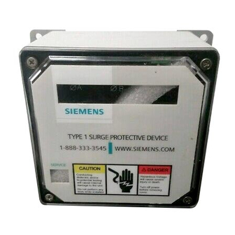
N.C. and Common terminals. During an inoperative condition, the SPDs dry contact would change state from normally closed to open. We generally suggest the Normally Closed configuration because it will detect a wiring defect, such as cut wire(s), where N.O. will not. Please note: Dry Contacts are designed for low voltage or control signals only. Maximum switching current is 5A Maximum switching voltage is 240V DC or AC. Higher energy applications require additional relay implementation TYPE 1 SURGE PROTECTIVE DEVICE outside the SPD. An optional Remote Monitor accessory is available to provide visual 1-888-333-3545 WWW.SIEMENS.COM and audible status. The Remote Monitor will consume one of the two sets of Dry Contacts. SERVICE Remote Monitor Accessory Option CAUTION V DANGER Conducting Hazardous Voltage A Remote Monitor is available for remote annunciation. It requires a dielectric and/or will cause severe standalone 120V power source (wall plug transformer) and uses one hi-potential testing injury or death. -
Page 10: Maintenance
A failed SPD is usually a sign of other implied. Additionally, the company is not be responsible for incidental problems within the electrical distribution system. As a generalization, or consequential damages resulting from any defect in any product or the single largest cause of SPD failures is reference to ground issues. component thereof. If the SPD shows problems on startup, there is reasonable chance of bonding/grounding/misapplication issue. This permanently damages The sales contract contains the entire obligation of Siemens. This the unit. If not corrected, it will happen again. instruction manual shall not become part of or modify any prior existing agreement, commitment or relationship. Technical Support 1.888.333.3545 Prior to calling Siemens TPS3 Technical Support for assistance or ordering parts, please have the following information available:... - Page 12 Siemens Industry, Inc. Building Technologies Division 5400 Triangle Parkway Norcross, GA 30092 888-333-3545 info.us@siemens.com 8.9.10.al #8174...
Need help?
Do you have a question about the TPS3 11 and is the answer not in the manual?
Questions and answers