
Related Manuals for Siemens TPS4-01


Summary of Contents for Siemens TPS4-01
- Page 1 Installation Guide / User Manual TPS4-01 and L1 for P1-P2-P3 Panels Surge Protection Devices usa.siemens.com/spd...
- Page 2 For further information, please review latest editions of sensitive equipment. NEC® Art. 285, UL 1449, contact your local Siemens sales office or contact Siemens TPS Tech Support at 800-333-7421. Voltage Rating Prior to installing the TPS4 SPD, verify that the unit has...
- Page 3 (a) Is trained and authorized to energize, deenergize, clear, ground and tag circuits and equipment in accordance shipping company and forward a copy to your local Siemens with established safety practices. sales office.
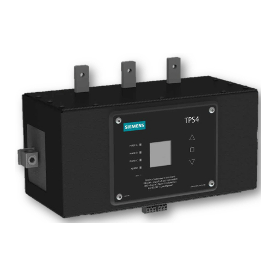
- Page 4 TPS4-01 Surge Protection Device | Installation Guide / User Manual Table 2: Model Number Catalog Logic TPS4 01 SPD for “RP1”, P2, P3 Lighting Panelboards, MCC and Busway General Suppressor Series TPS4 Catalog # Voltage Code Surge Current Rating Options (1 Alpha numeric Character) A = 240/120V ,1Ø, 3W (Figure 1)
- Page 5 Installation Guide / User Manual | TPS4-01 Surge Protection Device General Information System Grounding An equipment grounding conductor must be used on all This device features internal overcurrent and electrical circuits connected to the SPD. overtemperature protection that will disconnect affected...
- Page 6 (Item 3). The mounting plates should be attached to the The following instructions are for the installation of the TPS4 with the offset oriented towards the top of the unit. Siemens TPS4 01 and L1 SPD modules in Siemens Revised P1 Torque Screws to values listed. (RP1) lighting panelboards.
- Page 7 Installation Guide / User Manual | TPS4-01 Surge Protection Device W Option Instruction: The W option includes repositioned phase connection tabs that allow for wire connections to a circuit breaker within the panelboard. This differs from non-W models, which bolts directly to bus bars.
- Page 8 The following instructions are for the installation of the installed TPS3 or TPS4 unit.) Siemens TPS4 01 and L1 SPD modules in Siemens P2 and P3 lighting panelboards (also for field replacement.) Step 3) Attach TPS4 Mounting Plates (Item 2, 2 Places) to TPS4 using 10- 32 SEM screws with captive lock washer (Item 3).
- Page 9 Display Rotation The following instructions are for rotating the display assembly in the Siemens TPS4 01 and L1 SPD modules. The display may be rotated if care is taken to not unduly crimp/ damage the ribbon cable that feeds the display. If the display...
- Page 10 TPS4-01 Surge Protection Device | Installation Guide / User Manual Operation TPS4 surge protective devices require minimal attention after installation. TPS4’s contain diagnostic circuits which monitor the suppressor’s status continuously and automatically. All phase indicators and controls are located on the display panel of the unit.
- Page 11 Installation Guide / User Manual | TPS4-01 Surge Protection Device LED Operation • Each SPD contains 1 dual color LED per phase shown in the appropriate voltage configuration. • The SPD also includes a Red Alarm LED. When the LEDs are green complete protection is present.
- Page 12 TPS4-01 Surge Protection Device | Installation Guide / User Manual Adjust Date Screen The Adjust Date Screen will allow you to set the date of the SPD. Use the UP/ DOWN buttons to adjust the value in the selected field until you have the correct value.
- Page 13 Installation Guide / User Manual | TPS4-01 Surge Protection Device About Screen The About Screen displays the manufacturer’s information, the model number and the serial numberfor this specific SPD. Pressing the CENTER button will return you to the Main Menu Screen.
- Page 14 TPS4-01 Surge Protection Device | Installation Guide / User Manual Protection Loss When the SPD detects a Protection Loss this animation will be shown. It will remain on screen until acknowledged by an operator. Any subsequent events that occur while the disconnection event animation is on screen will be registered and queued for acknowledgment.
- Page 15 Audible Alarm will cycle. This condition requires immediate Corrective Maintenance (Repair) attention as the SPD will fail. The Siemens TPS4 unit is designed for years of reliable, Incorrectly bonded distribution systems damage SPDs. trouble- free operation. Unfortunately, in an extreme case, If the XO or N-G bonding jumper is not installed, the you may experience an alarm condition.
- Page 16 Actual results are dependent on variable conditions. Accordingly, Siemens does not make representations, warranties, or assurances as to the accuracy, currency or completeness of the content contained herein. If requested, we will provide specific technical data or specifications with respect to any customer’s particular applications.
Need help?
Do you have a question about the TPS4-01 and is the answer not in the manual?
Questions and answers