
Related Manuals for Siemens 3EL2


Summary of Contents for Siemens 3EL2
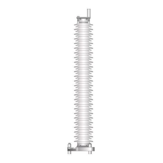
- Page 1 Surge Arrester Type 3EL2 Operating instructions Order-No.: 928 00047 176 Siemens Aktiengesellschaft Alle Rechte vorbehalten.. © Siemens AG • 07/2003...
-
Page 2: Table Of Contents
Technical data Description Design Mode of operation Transportation and storage Screwed joints Installation _______________________________________________________________________8 Accessories Place of installation Mounting the components Installing of the arrester Grounding Terminal Exploded view ___________________________________________________________________14 Maintenance_____________________________________________________________________16 Disposal arrester and arrester accessories © Siemens AG • 07/2003... - Page 3 This information is intended for the correct installation of this product. Siemens has no control over the condi- tion of the network, which can be greatly affected by the installation of a product. It is the responsibility of the user to chose the appropriate method of installation.
-
Page 4: Technical Data
The 3EL2 surge arrester serves to protect the insulation of a system (or of one of its components) from undue stresses resulting from overvoltages. Technical data The standard model is suitable for an installation altitude of up to 1000 m above sea-level and for a rated frequency between 48 Hz and 62 Hz. -
Page 5: Description
(“discharge voltage”). Here the discharge currents may range up to 2 kA in the case of switching surges and 1 - 10 - 20 kA in the case of lightning surges. © Siemens AG • 07/2003... -
Page 6: Transportation And Storage
All of the screws, terminals and supplementary equipment (tell-tale spark gap, surge counter) required for assembly and installation are supplied in an accessory pack. Note To avoid damaging the insulators, do not remove the assembly and shipping protector until assembly and installation has been completed. © Siemens AG • 07/2003... -
Page 7: Screwed Joints
25 ± 4 ft lb M 12: 60 ± 5 Nm 43 ± 4 ft lb M 16: 90 ± 10 Nm 65 ± 7 ft lb M 20: 105 ± 10 Nm 75 ± 7 ft lb © Siemens AG • 07/2003... -
Page 8: Installation
The arresters must be installed or suspended vertically. If they need to be installed in a non-vertical position, you should first contact the manufacturer. Mounting the components The individual components for mounting are shown in the drawing in [=> on page 15]. © Siemens AG • 07/2003... -
Page 9: Installing Of The Arrester
Shim plates between the individual arrester units are not allowed. Before the top unit is located in place, it is advisable to fit the outer grading ring struts [3/Fig. 17], [4/Fig. 17] and the terminal plate [10/Fig. 17] to the upper flange. © Siemens AG • 07/2003... - Page 10 Put according to the drilling plan the three lower insulating sockets [Fig. 10] to the holes of the support. The base plate and the upper insulating sockets can be mounted with three bolts M12 × 140 on the © Siemens AG • 07/2003...
- Page 11 M20 × 110 on the lower insulating sockets. The arrester [5] must be placed and mounted with four bolts M10 × 50 on the base plate by means of appropriate lifting gear (crane, tackle) comprising slings and lifting lugs [Fig. 7]. © Siemens AG • 07/2003...
-
Page 12: Grounding
Pay attention to the electro-chemical compatibility of the materials utilised. Terminal with cable eye The terminal must be mounted with a cable eye according to [Fig. 13]. © Siemens AG • 07/2003... - Page 13 If the terminal is mounted by means of a bolt terminal [Fig. 14] or a flat terminal [Fig. 15], [Fig. 16], the necessary accessories are already installed by the manufacturer. Fig. 14 Bolt terminal Fig. 15 Flat terminal DIN Fig. 16 Flat terminal NEMA © Siemens AG • 07/2003...
-
Page 14: Exploded View
Washer 21 Insulating tube B20 × 1,2 Insulating socket Spring washer B20 Nut M20 Screw M12 × 30 Spring washer B12 Washer 13 Nut M12 Screw M12 × 30 14c, Spring washer B12 Washer 13 © Siemens AG • 07/2003... - Page 15 Fig. 17 Überspannungsableiter 3EL2 © Siemens AG • 07/2003...
-
Page 16: Maintenance
The following materials have been used to make up the device: Steel, aluminium, glass-fibre- reinforced plastics, electronic components and silicon rubber (VMQ), ceramics (metal oxide). According to current waste disposal techniques, arresters type 3EL2 cannot be used for neither mate- rial nor thermal purposes..
Need help?
Do you have a question about the 3EL2 and is the answer not in the manual?
Questions and answers